

Page 1
This datasheet contains new product information. Myson Technology reserves the rights to modify the product specification without notice.
No liability is assumed as a result of the use of this procuts. No rights under any patent accompany the sales of the product.
1/18 MTV121 Revision 5.0 06/29/1999
MTV121MYSON
TECHNOLOGY
FEATURES GENERAL DESCRIPTION
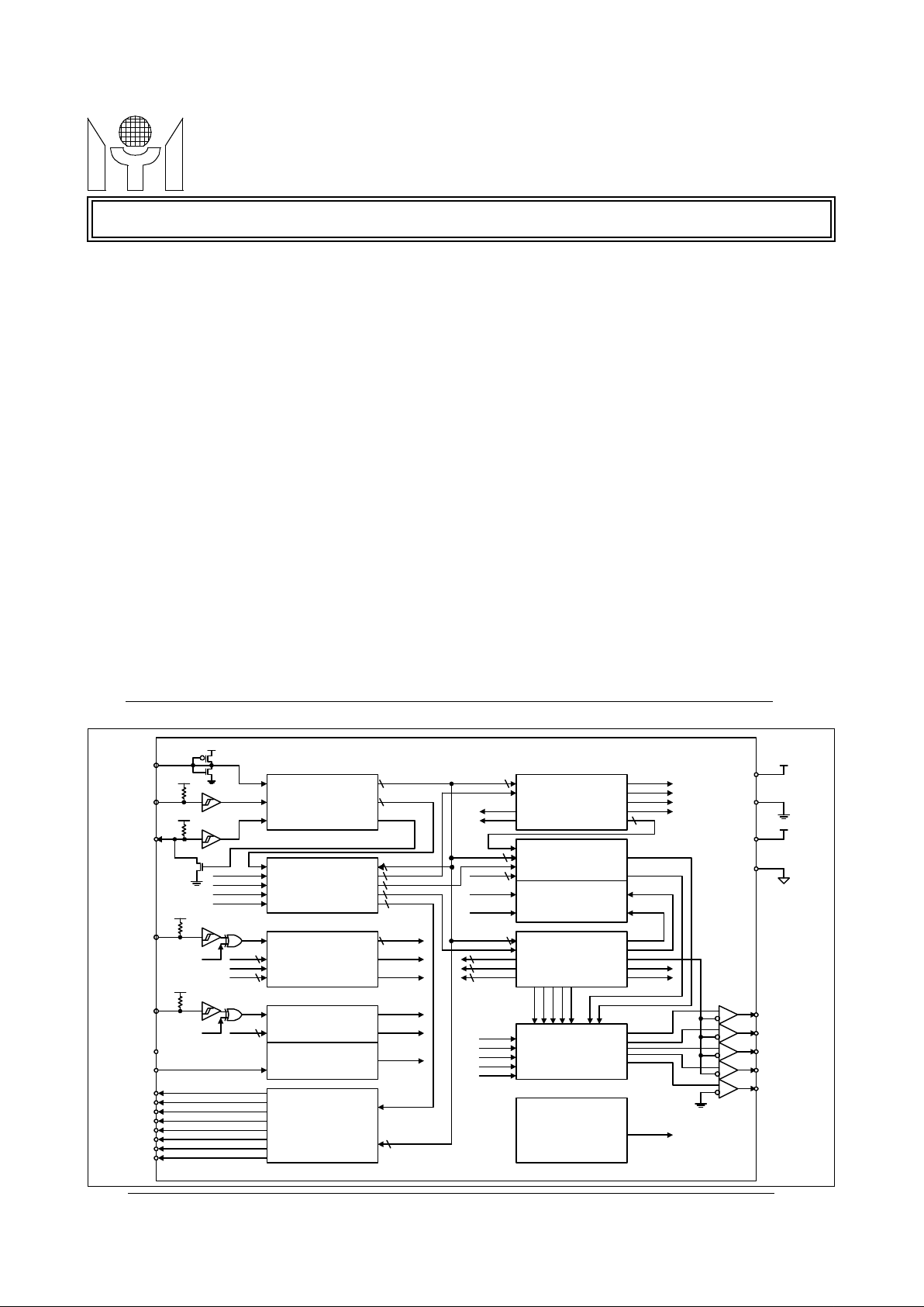
BLOCK DIAGRAM
• Horizontal sync input may be up to 130 KHz.
• Acceptable wide-range pixel clock up to 96MHz.
• Full screen display consists of 15 (rows) by 30 (columns)
characters.
• 12 x 18 dot matrix per character.
• Total 272 characters and graphic fonts including 256
standard and 16 multi-color mask ROM fonts.
• 8 color selectable maximum per display character.
• 7 color selectable maximum for character background.
• Double character height and/or width control.
• Programmable positioning for display screen center.
• Bordering, shadowing and blinking effect.
• Programmable character height (18 to 71 lines) control.
• Row to row spacing register to manipulate the constant
display height.
• 4 programmable background windows with multi-level
operation and shadowing on window effect.
• Software clears bit for full-screen erasing.
• Half tone and fast blanking output.
• Fade-in/fade-out effect.
• 8 channels 8 bits PWM D/A converters output.
• Compatible to SPI bus or I2C interface with slave
address 7AH (Slave address is mask option).
• 16 / 20 / 24 pins PDIP / SOP package.
Super On-Screen-Display for LCD Monitor
MTV121 is designed for LCD monitor applications
to display the built-in characters or fonts onto an LCD
monitor screen. The display operation is by transferring data and control information from micro controller to RAM through a serial data interface. It can
execute full screen display automatically and specific functions such as character background color,
bordering, shadowing, blinking, double height and
width, font by font color control, frame positioning,
frame size control by character height and row-torow spacing, horizontal display resolution, full-screen
erasing, fade-in/fade-out effect, windowing effect and
shadowing on window.
MTV121 provide 256 standard and 16 multi-color
fonts for more efficacious applications. The full OSD
menu is formed of 15 rows x 30 columns which can
be positioned on anywhere of the monitor screen by
changing vertical delay or horizontal delay.
Moreover, MTV121 also provide 8 PWM DAC
channels with 8 bits resolution and a PWM clock output for external digital to analog control.
SERIAL DATA
INTERFACE
ADDRESS BUS
ADMINISTRATOR
VERTICAL
DISPLAY
CONTROL
DISPLAY & ROW
CONTROL
REGISTERS
COLOR
ENCODER
WINDOWS &
FRAME
CONTROL
WRWGWB
FBKGC
BLANK
LUMAR
LUMAG
LUMAB
BLINK
VCLKX
DATA
VERTD
HORD
CH
8
8
7
BSEN
SHADOW
OSDENB
HSP
VSP
HORIZONTAL
DISPLAY CONTROL
CLOCK
GENERATOR
8
DATA
LPN
CWS
VCLKS
5
DATA
CWS
CHS
8 LUMAR
LUMAG
LUMAB
BLINK
CRADDR
8
LUMA
BORDER
ARWDB
HDREN
VCLKX
HORD
8
CH
CHS
VERTD
7
8
LPN
NROW
VDREN
5
RCADDR
DADDR
FONTADDR
WINADDR
PWMADDR
5
9
9
5
5
ARWDB
HDREN
VDREN
NROW
DATA
ROW, COL
ACK
8
9
CHARACTER ROM
USER FONT RAM
LUMINANCE &
BORDGER
GENERATOR
VDD
VSS
VDDA
VSSA
ROUT
GOUT
BOUT
FBKG
HTONE
HFLB
NC
XIN
VFLB
SSB
SCK
SDA
VSP
HSP
PWM D/A
CONVERTER
PWM0
PWM1
PWM2
PWM3
PWM4
PWM5
PWM6
PWM7
8
DATA
8
POWER ON
RESET
PRB
Page 2
2/18 MTV121 Revision 5.0 06/29/1999
MTV121MYSON
TECHNOLOGY
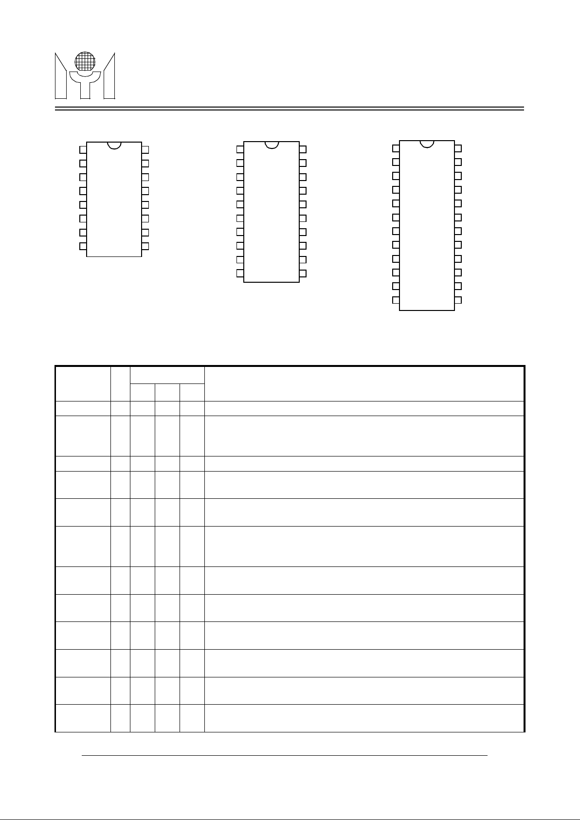
1.0 PIN CONNECTION
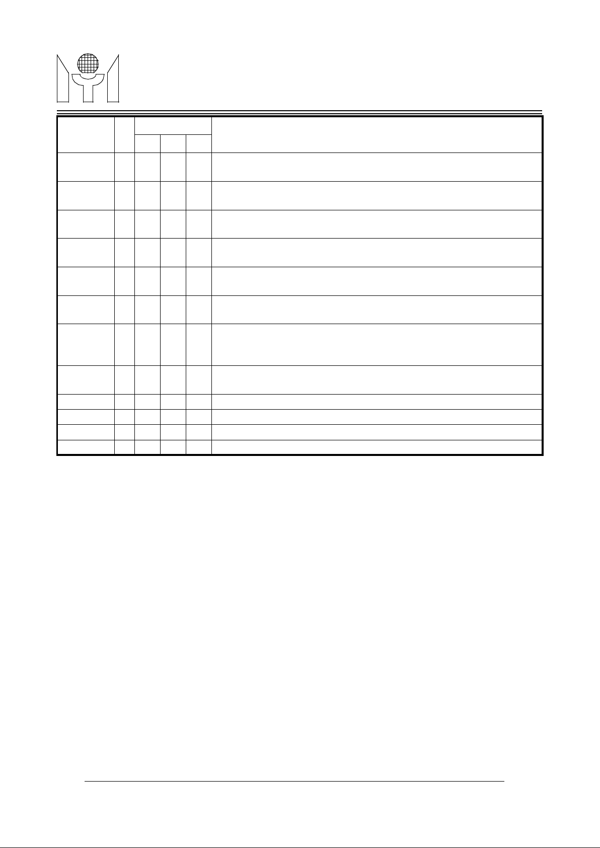
2.0 PIN DESCRIPTIONS
Name I/O
Pin No.
Descriptions
N16 N20 N24
VSS - 1 1 1 Ground. This ground pin is used to internal circuitry.
XIN I 2 2 2 Pixel clock input. This is a clock input pin. MTV121 is driven by an exter-
nal pixel clock source for all the logics inside. The frequency of XIN must
be the integral time of pin HFLB.
NC I 3 3 3 No connection.
VDD - 4 4 4 Power supply. Positive 5 V DC supply for internal circuitry. And a 0.1uF
decoupling capacitor should be connected across to VDD and VSS.
HFLB I 5 5 5 Horizontal input. This pin is used to input the horizontal synchronizing
signal. It is a leading edge triggered and has an internal pull-up resistor.
SSB I 6 6 6 Serial interface enable. It is used to enable the serial data and is also
used to select the operation of I2C or SPI bus. If this pin is left floating, I2C
bus is enabled, otherwise the SPI bus is enabled.
SDA I 7 7 7 Serial data input. The external data transfer through this pin to internal
display registers and control registers. It has an internal pull-up resistor.
SCK I 8 8 8 Serial clock input. The clock-input pin is used to synchronize the data
transfer. It has an internal pull-up resistor.
PWM0 O - 9 9 Open-Drain PWM D/A converter 0. The output pulse width is program-
mable by the register of Row 15, Column 23.
PWM1 O - 10 10 Open-Drain PWM D/A converter 1. The output pulse width is program-
mable by the register of Row 15, Column 24.
PWM2 O - - 11 Open-Drain PWM D/A converter 2. The output pulse width is program-
mable by the register of Row 15, Column 25.
PWM3 O - - 12 Open-Drain PWM D/A converter 3. The output pulse width is program-
mable by the register of Row 15, Column 26.
VSSA
XIN
NC
VDDA
HFLB
SSB
SDA
SCK
VSS
ROUT
GOUT
BOUT
FBKG
HTONE/PWMCK
VFLB
VDD
16
15
14
13
12
11
10
9
1
2
3
4
5
6
7
8
MTV121
VSSA
XIN
NC
VDDA
HFLB
SSB
SDA
SCK
PWM0
PWM1
PWM2
PWM3
VSS
ROUT
GOUT
BOUT
FBKG
HTONE/PWMCK
VFLB
VDD
PWM7
PWM6
PWM5
PWM4
24
23
22
21
20
19
18
17
16
15
14
13
1
2
3
4
5
6
7
8
9
10
11
12
MTV121N24
VSSA
XIN
NC
VDDA
HFLB
SSB
SDA
SCK
PWM0
PWM1
VSS
ROUT
GOUT
BOUT
FBKG
HTONE/PWMCK
VFLB
VDD
PWM7
PWM6
20
19
18
17
16
15
14
13
12
11
1
2
3
4
5
6
7
8
9
10
MTV121N20
Page 3
3/18 MTV121 Revision 5.0 06/29/1999
MTV121MYSON
TECHNOLOGY
3.0 FUNCTIONAL DESCRIPTIONS
3.1 SERIAL DATA INTERFACE
The serial data interface receives data transmitted from an external controller. And there are 2 types of bus
can be accessed through the serial data interface, one is SPI bus and other is I2C bus.
3.1.1 SPI bus
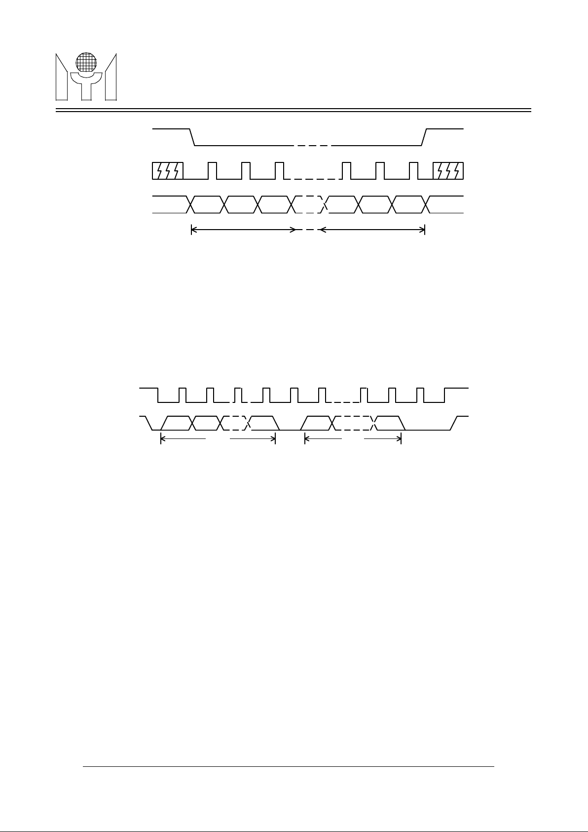
While SSB pin is pulled to "high" or "low" level, the SPI bus operation is selected. And a valid transmission
should be starting from pulling SSB to "low" level, enabling mtv121 to receiving mode, and retain "low" level
until the last cycle for a complete data packet transfer. The protocol is shown in Figure1.
PWM4 O - - 13 Open-Drain PWM D/A converter 4. The output pulse width is program-
mable by the register of Row 15, Column 27.
PWM5 O - - 14 Open-Drain PWM D/A converter 5. The output pulse width is program-
mable by the register of Row 15, Column 28.
PWM6 O - 11 15 Open-Drain PWM D/A converter 6. The output pulse width is program-
mable by the register of Row 15, Column 29.
PWM7 O - 12 16 Open-Drain PWM D/A converter 7. The output pulse width is program-
mable by the register of Row 15, Column 30.
VDD - 9 13 17 Power supply. Positive 5 V DC supply for internal circuitry and a 0.1uF
decoupling capacitor should be connected across to VDD and VSS.
VFLB I 10 14 18 Vertical input. This pin is used to input the vertical synchronizing signal.
It is leading triggered and has an internal pull-up resistor.
HTONE /
PWMCK
O 11 15 19 Half tone output / PWM clock output. This is a multiplexed pin selected
by PWMCK bit. This pin can be a PWM clock or used to attenuate R, G, B
gain of VGA for the transparent windowing effect.
FBKG O 12 16 20 Fast Blanking output. It is used to cut off external R, G, B signals of
VGA while this chip is displaying characters or windows.
BOUT O 13 17 21 Blue color output. It is a blue color video signal output.
GOUT O 14 18 22 Green color output. It is a green color video signal output.
ROUT O 15 19 23 Red color output. It is a red color video signal output.
VSS - 16 20 24 Ground. This ground pin is used to internal circuitry.
Name I/O
Pin No.
Descriptions
N16 N20 N24
Page 4
4/18 MTV121 Revision 5.0 06/29/1999
MTV121MYSON
TECHNOLOGY
There are three transmission formats shown as below:
Format (a) R - C - D → R - C - D → R - C - D
Format (b) R - C - D → C - D → C - D → C - D
Format (c) R - C - D → D → D → D → D → D
Where R=Row address, C=Column address, D=Display data
3.1.2 I2C bus
I2C bus operation is only selected when SSB pin is left floating. And a valid transmission should be starting
from writing the slave address 7AH, which is mask option, to MTV121. The protocol is shown in Figure2.
There are three transmission formats shown as below:
Format (a) S - R - C - D → R - C - D → R - C - D
Format (b) S - R - C - D → C - D → C - D → C - D
Format (c) S - R - C - D → D → D → D → D → D
Where S=Slave address, R=Row address, C=Column address, D=Display data
Each arbitrary length of data packet consists of 3 portions viz, Row address (R), Column address (C), and
Display data (D). Format (a) is suitable for updating small amount of data which will be allocated with different
row address and column address. Format (b) is recommended for updating data that has same row address
but different column address. Massive data updating or full screen data change should use format (c) to
increase transmission efficiency. The row and column address will be incremented automatically when the
format (c) is applied. Furthermore, the undefined locations in display or fonts RAM should be filled with
dummy data.
There are 2 types of data should be accessed through the serial data interface, one is ADDRESS bytes of display registers, and other is ATTRIBUTE bytes of display registers, the protocol are same for all except bit5 of
row address. The MSB(b7) is used to distinguish row and column addresses when transferring data from
external controller. The bit6 of column address is used to differentiate the column address for format (a), (b)
and format (c) respectively. Bit5 of row address for display register is used to distinguish ADDRESS byte
when it is set to "0" and ATTRIBUTE byte when it is set to "1". See Table 1 on page 4.
MS
B
LSB
SSB
SCK
SDA
first byte last byte
FIGURE 1. Data Transmission Protocol (SPI)
FIGURE 2. Data Transmission Protocol (I2C)
SCK
SDA
first byte
¡@¡@¡@¡@
¡@
START ACK
second byte last byte
ACK STOP
B7 B6 B0 B7 B0
Page 5
5/18 MTV121 Revision 5.0 06/29/1999
MTV121MYSON
TECHNOLOGY
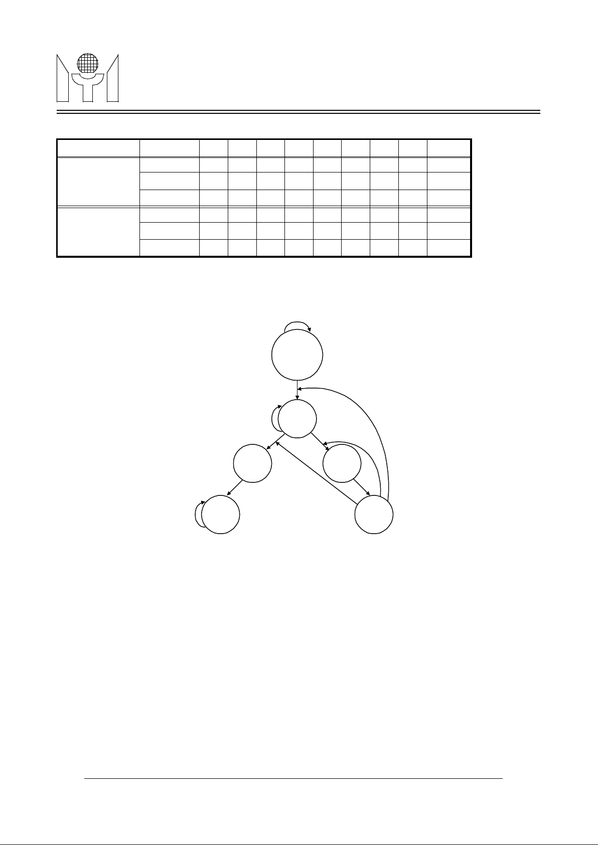
The data transmission is permitted to change from format (a) to format (b) and (c), or from format (b) to format
(a), but not from format (c) back to format (a) and (b). The alternation between transmission formats is configured as the state diagram shown in Figure3.
3.2 Address bus administrator
The administrator manages bus address arbitration of internal registers or user fonts RAM during external
data write in. The external data write through serial data interface to registers must be synchronized by internal display timing. In addition, the administrator also provides automatic increment to address bus when external write using format (c).
3.3 Vertical display control
The vertical display control can generates different vertical display sizes for most display standards in current
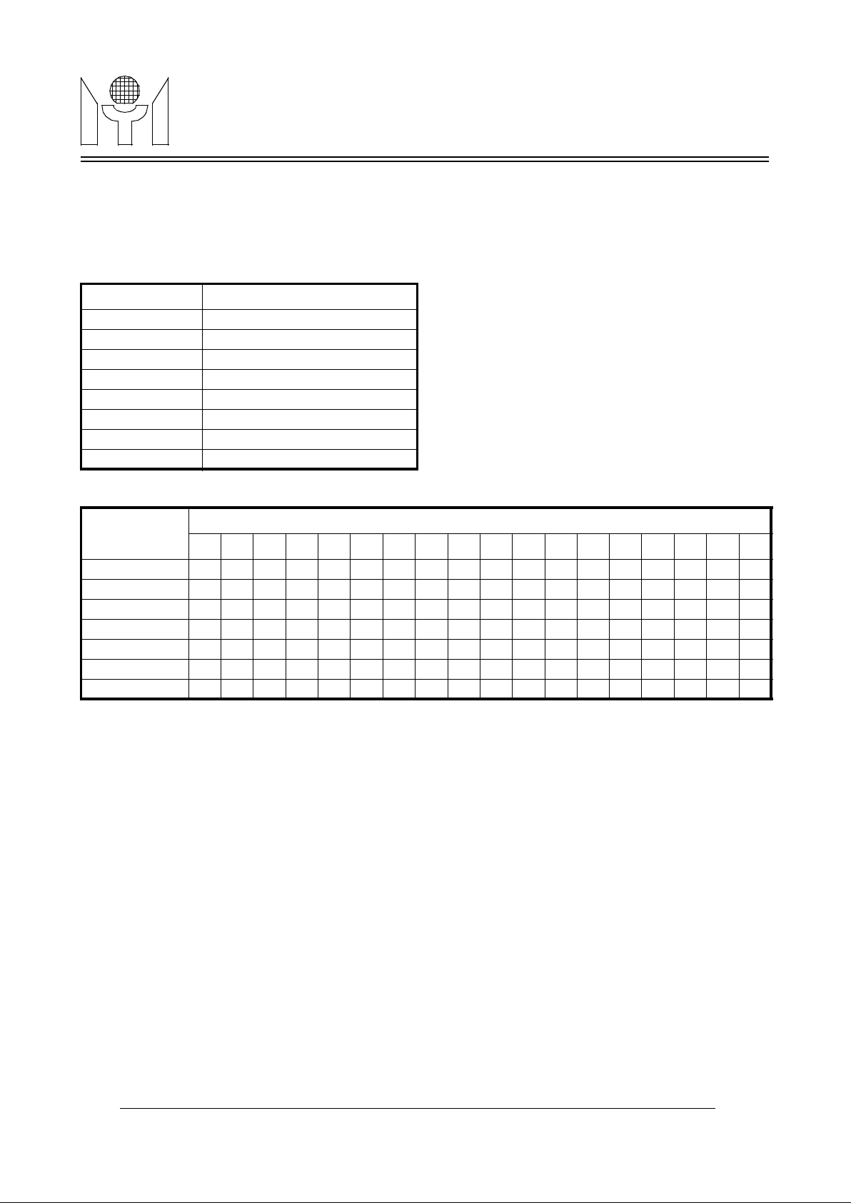
monitors. The vertical display size is calculated with the information of double character height bit(CHS), vertical display height control register(CH6-CH0).The algorithm of repeating character line display are shown as
Table 2 and Table 3. The programmable vertical size range is 270 lines to maximum 2130 lines.
TABLE 1. The configuration of transmission formats.
Address b7 b6 b5 b4 b3 b2 b1 b0 Format
Address Bytes
of Display Reg.
Row 1 0 0 x R3 R2 R1 R0 a,b,c
Column
ab
0 0 x C4 C3 C2 C1 C0 a,b
Column
c
0 1 x C4 C3 C2 C1 C0 c
Attribute Bytes
of Display Reg.
Row 1 0 1 x R3 R2 R1 R0 a,b,c
Column
ab
0 0 x C4 C3 C2 C1 C0 a,b
Column
c
0 1 x C4 C3 C2 C1 C0 c
Initiate
ROW
COL
c
COL
ab
DA
c
DA
ab
1, X
0, 1
0, 0
X, X
X, X
0, 1
1, X
1, X
format (a)
format (b)
format (c)
X, X
0, X
Input = b7, b6
0, 0
FIGURE 3. Transmission State Diagram
Page 6
6/18 MTV121 Revision 5.0 06/29/1999
MTV121MYSON
TECHNOLOGY
The vertical display center for full screen display could be figured out according to the information of vertical
starting position register (VERTD) and VFLB input. The vertical delay starting from the leading edge of VFLB,
is calculated with the following equation:
Vertical delay time = ( VERTD * 4 + 1 ) * H Where H = one horizontal line display time
Note:" v " means the nth line in the character would be repeated once, while " - " means the nth line in the
character would not be repeated.
3.4 Horizontal display control
The horizontal display control is used to generate control timing for horizontal display based on double character width bit (CWS), horizontal positioning register (HORD), horizontal resolution register (HORR), and
HFLB input. A horizontal display line consists of (HORR*12) dots which include 360 dots for 30 display characters and the remaining dots for blank region. The horizontal delay starting from HFLB leading edge is calculated with the following equation,
Horizontal delay time = ( HORD * 6 + 49) * P Where P = 1 XIN pixel display time
3.5 Display & Row control registers
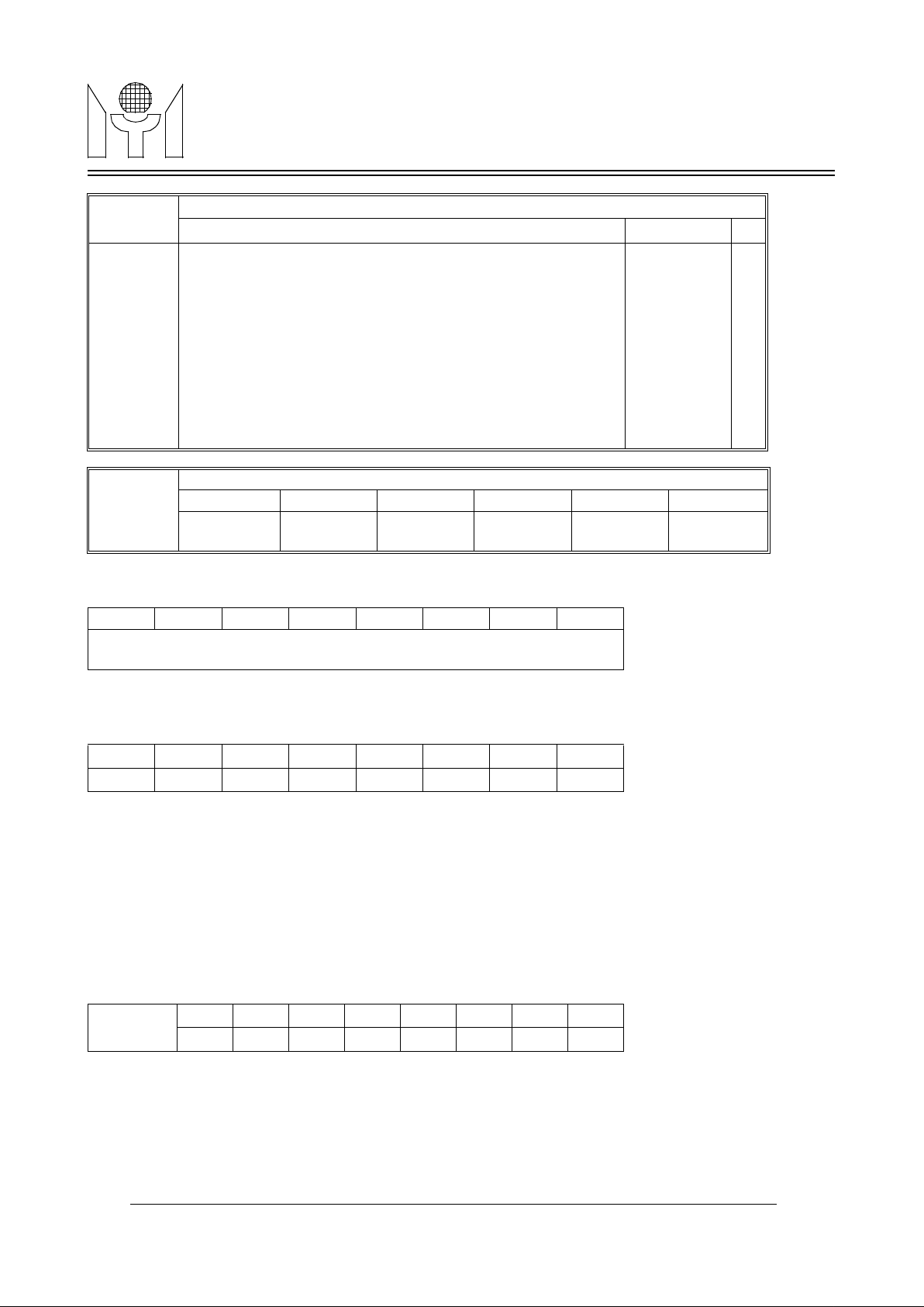
The internal RAM contains display and row control registers. The display registers have 450 locations which
are allocated between (row 0, column 0) to (row 14, column 29), as shown in Figure4. Each display register
has its corresponding character address on ADDRESS byte, its corresponding background color, 1 blink bit
and its corresponding color bits on ATTRIBUTE bytes. The row control register is allocated at column 30 for
row 0 to row 14, it is used to set character size to each respective row. If double width character is chosen,
only even column characters could be displayed on screen and the odd column characters will be hidden.
TABLE 2. Repeat line weight of character
CH6 - CH0 Repeat Line Weight
CH6,CH5=11 +18*3
CH6,CH5=10 +18*2
CH6,CH5=0x +18
CH4=1 +16
CH3=1 +8
CH2=1 +4
CH1=1 +2
CH0=1 +1
TABLE 3. Repeat line number of character
Repeat Line
Weight
Repeat Line #
0 1 2 3 4 5 6 7 8 9 10 11 12 13 14 15 16 17
+1 - - - - - - - - v - - - - - - - - +2 - - - - v - - - - - - - v - - - - +4 - - v - - - v - - - v - - - v - - -
+8 - v - v - v - v - v - v - v - v - +16 - v v v v v v v v v v v v v v v v +17 v v v v v v v v v v v v v v v v v +18 v v v v v v v v v v v v v v v v v v
Page 7
7/18 MTV121 Revision 5.0 06/29/1999
MTV121MYSON
TECHNOLOGY
FIGURE 4. Memory Map
ADDRESS BYTE
CRADDR - Define ROM character address.
ATTRIBUTE BYTE
BGR, BGG, BGB - These three bits define the color of the background for its relative address character. If all
three bits are clear, no background will be shown(transparent). Therefore, total 7 back-
ground color can be selected.
BLINK - Enable blinking effect while this bit is set to " 1 ". And the blinking is alternate per 32 vertical frames.
R, G, B - These three bits are used to specify its relative address character color.
1. Row Control Registers, (Row 0 - 14)
CHS - Define double height character to the respective row.
CWS - Define double width character to the respective row.
3.6 Character ROM
ROW # COLUMN #
0 1 28 29 30 31
0
1
13
14
DISPLAY
REGISTERS
ROW
CTRL REG
R
E
S
E
R
V
E
D
ROW 15
COLUMN#
0 2 3 5 6 8 9 11 12 22 23 30
WINDOW1 WINDOW2 WINDOW3 WINDOW4 FRAME
CRTL REG
PWM D/A
CRTL REG
b7 b6 b5 b4 b3 b2 b1 b0
CRADDR
MSB LSB
b7 b6 b5 b4 b3 b2 b1 b0
- BGR BGG BGB BLINK R G B
COLN 30
b7 b6 b5 b4 b3 b2 b1 b0
- - - - - - CHS CWS
Page 8
8/18 MTV121 Revision 5.0 06/29/1999
MTV121MYSON
TECHNOLOGY
mtv121 character ROM contains 272 built-in characters and symbols including 256 standard fonts and 16
multi-color fonts. The 256 standard fonts are located from address 0 to 255. And the 16 multi-color fonts are
located from address 240 to 255 while CFONT bit is set to “1”. Each character and symbol consists of 12x18
dots matrix. The detail pattern structures for each character and symbols are shown in “CHARACTERS AND
SYMBOLS PATTERN” on page18.
3.7 Multi-Color Font
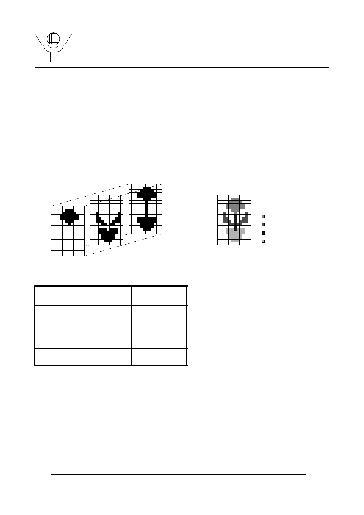
The color fonts comprises three different R, G, B fonts. When the code of color font is accessed, the separate
R/G/B dot pattern is output to corresponding R/G/B output. See Figure5 for the sample displayed color font.
Note: No black color can defined in color font, black window underline the color font can make the dots
become black in color. The detail pattern structures for each character and symbols are shown in “CHARACTERS AND SYMBOLS PATTERN” on page18.
FIGURE 5. Example of Multi-Color Font
TABLE 4. The Multi-Color Font Color Selection
3.8 Luminance & border generator
There are 2 shift registers included in the design which can shift out of luminance and border dots to color
encoder. The bordering and shadowing feature is configured in this block. For bordering effect, the character
will be enveloped with blackedge on four sides. For shadowing effect, the character is enveloped with
blackedge for right and bottom sides only.
3.9 Window and frame control
The display frame position is completely controlled by the contents of VERTD and HORD. The window size
and position control are specified in column 0 to 11 on row 15 of memory map, as shown in Figure4. Window
R G B
Background Color 0 0 0
Blue 0 0 1
Green 0 1 0
Cyan 0 1 1
Red 1 0 0
Magent 1 0 1
Yellow 1 1 0
White 1 1 1
R
G
B
Magent
Green
Cyan
Blue
Page 9
9/18 MTV121 Revision 5.0 06/29/1999
MTV121MYSON
TECHNOLOGY
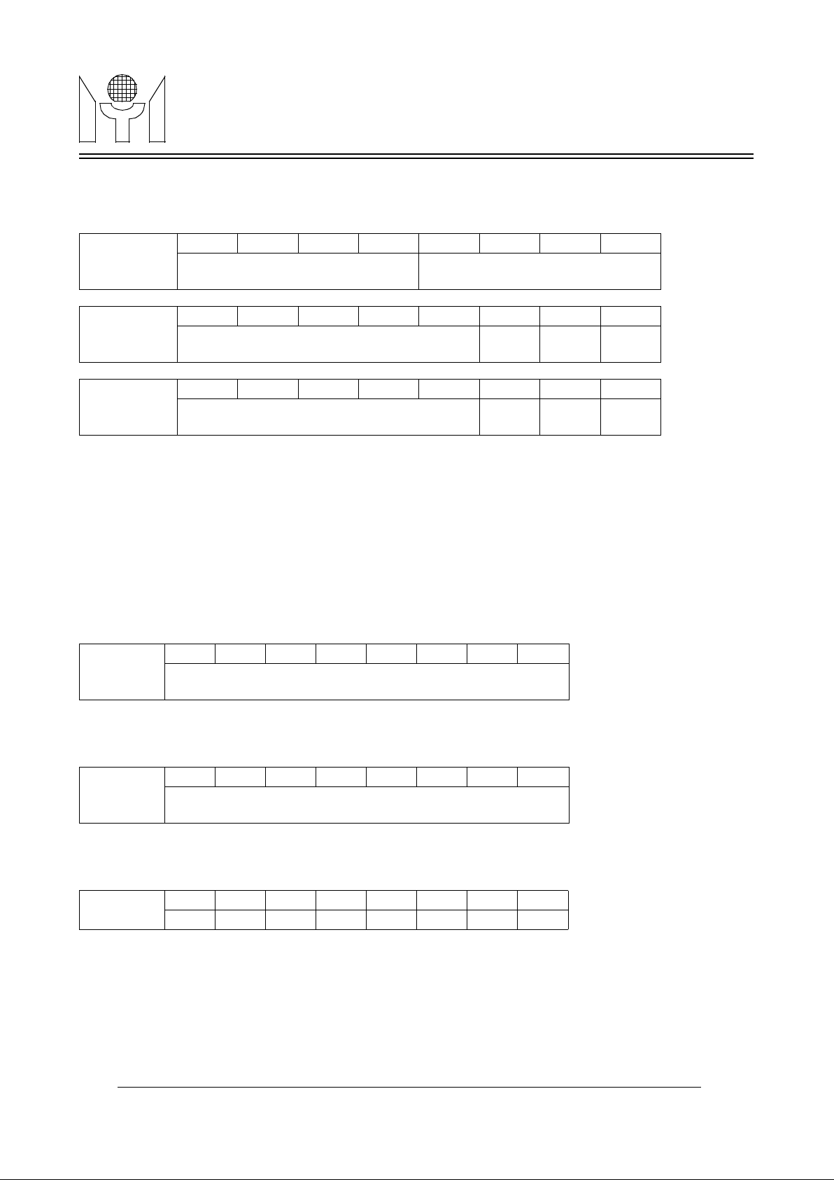
1 has the highest priority, and window 4 is the least, when two windows are overlapping. More detailed information is described as follows:
1. Window control registers,
ROW 15
START(END) ADDR - These addresses are used to specify the window size. It should be noted that when
the start address is greater than the end address, the window will be disabled.
WEN - Enable the window display.
WSHD - Enable shadowing on the window.
R, G, B - Specify the color of the relative background window.
2. Frame control registers,
ROW 15
VERTD - Specify the starting position for vertical display. The total steps are 256, and the increment of each
step is 4 Horizontal display lines. The initial value is 4 after power up.
HORD - Define the starting position for horizontal display. The total steps are 256, and the increment of each
step is 6 dots. The initial value is 15 after power up.
CH6-CH0 - Define the character vertical height, the height is programmable from 18 to 71 lines. The character
vertical height is at least 18 lines if the contents of CH6-CH0 is less than 18. For example, when
the contents is " 2 ", the character vertical height is regarded as equal to 20 lines. And if the contents of CH4-CH0 is greater than or equal to 18, it will be regarded as equal to 17. See Table 2
and Table 3 for detail description of this operation.
Column
0,3,6,OR 9
b7 b6 b5 b4 b3 b2 b1 b0
ROW START ADDR
MSB LSB
ROW END ADDR
MSB LSB
Column
1,4,7,OR 10
b7 b6 b5 b4 b3 b2 b1 b0
COL START ADDR
MSB LSB
WEN - WSHD
Column
2,5,8,OR 11
b7 b6 b5 b4 b3 b2 b1 b0
COL END ADDR
MSB LSB
R G B
Column 12
b7 b6 b5 b4 b3 b2 b1 b0
VERTD
MSBLSB
Column 13
b7 b6 b5 b4 b3 b2 b1 b0
HORD
MSBLSB
Column 14
b7 b6 b5 b4 b3 b2 b1 b0
- CH6 CH5 CH4 CH3 CH2 CH1 CH0
Page 10
10/18 MTV121 Revision 5.0 06/29/1999
MTV121MYSON
TECHNOLOGY
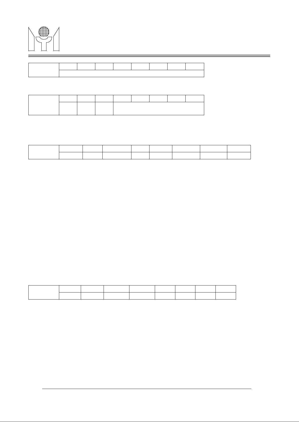
This byte is reserved for internal testing.
RSPACE - Define the row to row spacing in unit of horizontal line. That is, extra RSPACE horizontal lines will
be appended below each display row, and the maximum space is 31 lines. The initial value is 0
after power up.
OSDEN - Activate the OSD operation when this bit is set to "1". The initial value is 0 after power up.
BSEN - Enable the bordering and shadowing effect.
SHADOW - Activate the shadowing effect if this bit is set, otherwise the bordering is chosen.
FAN - Enable the fade-in/fade-out function when OSD is turned on from off state or vice verca. The function
roughly takes about one second to fully display the whole menu or to disappear completely.
BLANK - Force the FBKG pin output to high while this bit is set to "1".
WENCLR - Clear all WEN bits of window control registers when this bit is set to "1". The initial value is 0 after
power up.
RAMCLR - Clear all ADDRESS bytes, BGR, BGG, BGB and BLINK bits of display registers when this bit is set
to "1". The initial value is 0 after power up.
FBKGC - Define the output configuration for FBKG pin. When it is set to "0", the FBKG outputs during the dis-
playing of characters or windows, otherwise, it outputs only during the displaying of character.
TRIC - Define the driving state of output pins ROUT, GOUT, BOUT and FBKG when OSD is disabled. That
is, while OSD is disabled, these four pins will drive low if this bit is set to 1, otherwise these four pins
are in high impedance state. The initial value is 0 after power up.
FBKGP - Select the polarity of the output pin FBKG
= 1 ⇒Positive polarity FBKG output is selected.
= 0 ⇒Negative polarity FBKG output is selected.
The initial value is 1 after power up.
PWMCK - Select the output options to HTONE/PWMCK pin.
= 0 ⇒ HTONE option is selected.
= 1 ⇒ PWMCK option is selected with 50/50 duty cycle and synchronous with the input HFLB.
The frequency is selected by (PWM1, PWM0) shown as Table 5.
Column 15
b7 b6 b5 b4 b3 b2 b1 b0
Reserved
Column 16
b7 b6 b5 b4 b3 b2 b1 b0
- - - RSPACE
MSBLSB
Column 17
b7 b6 b5 b4 b3 b2 b1 b0
OSDEN BSEN SHADOW FAN BLANK WENCLR RAMCLR FBKGC
Column 18
B7 b6 b5 b4 b3 b2 b1 b0
TRIC FBKGP PWMCK DWE HSP VSP PWM1 PWM0
Page 11
11/18 MTV121 Revision 5.0 06/29/1999
MTV121MYSON
TECHNOLOGY
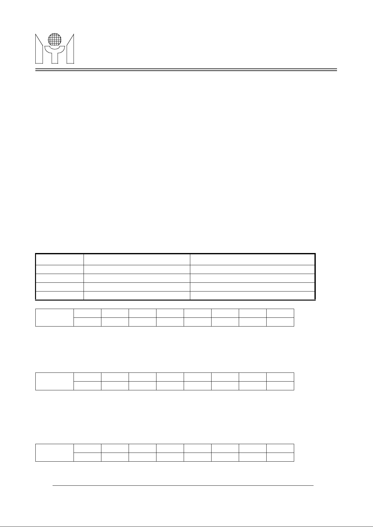
The initial value is 0 after power up.
DWE - Enable double width. When the bit is set to “1”, the display of OSD menu can change to half resolution
for double character width, and then the number of pixels of each line should be even. The initial value
is 0 after power up.
HSP - = 1 ⇒ Accept positive polarity Hsync input.
= 0 ⇒ Accept negative polarity Hsync input.
VSP - = 1 ⇒ Accept positive polarity Vsync input.
= 0 ⇒ Accept negative polarity Vsync input.
PWM1, PWM0 - Select the PWMCK output frequency.
= (0, 0) ⇒ XIN frequency /8
= (0, 1) ⇒ XIN frequency /4
= (1, 0) ⇒ XIN frequency /2
= (1, 1) ⇒ XIN frequency /1
The initial value is (0, 0) after power up.
Notes : When XIN is not present, don’t write data in any address. If data is written in any other address, a
malfunction may occur.
WSR, WSG, WSB - Define the color of shadowing on windows. The initial value is (0, 0, 0) after power up.
CSR, CSG, CSB - Define the color of bordering or shadowing on characters. The initial value is (0, 0, 0) after
power up.
CFONT - Enable 16 multi-color fonts.
= 0 ⇒ Character address 240 to 255 are connected to standard ROM fonts.
= 1 ⇒ Character address 240 to 255 are connected to 16 multi-color ROM fonts.
The initial value is 0 after power up.
TABLE 5. PWMCK Frequency and PWMDA sampling rate
(PWM1, PWM0) PWMCK Freq PWMDA sampling rate
( 0, 0 ) XIN frequency /8 XIN frequency /(8 * 256)
( 0, 1 ) XIN frequency /4 XIN frequency /(4 * 256)
( 1, 0 ) XIN frequency /2 XIN frequency /(2 * 256)
( 1 ,1 ) XIN frequency /1 XIN frequency /(1 * 256)
Column 19
B7 b6 b5 b4 b3 b2 b1 b0
- WSR WSG WSB - CSR CSG CSB
Column 20
B7 b6 b5 b4 b3 b2 b1 b0
- - - - - - - CFONT
Column 21
B7 b6 b5 b4 b3 b2 b1 b0
WW41 WW40 WW31 WW30 WW21 WW20 WW11 WW10
Page 12
12/18 MTV121 Revision 5.0 06/29/1999
MTV121MYSON
TECHNOLOGY
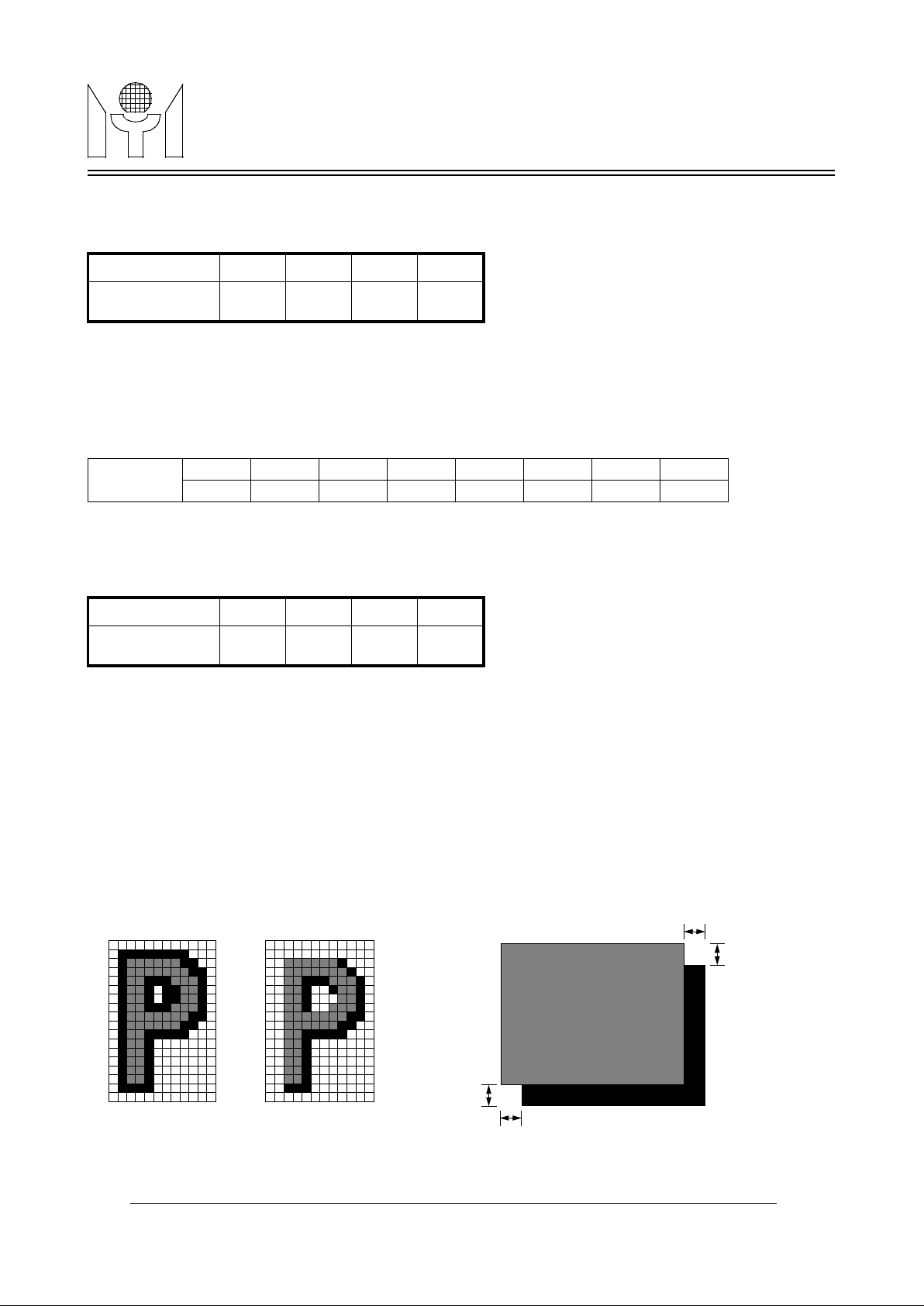
WW41, WW40 - Determines the shadow width of the window 4 when WSHD bit of th window 4 is enabled.
Please refer to the Table 6 for more details.
TABLE 6. Shadow Width Setting
WW31, WW30 - Determines the shadow width of the window 3 when WSHD bit of th window 3 is enabled.
WW21, WW20 - Determines the shadow width of the window 2 when WSHD bit of th window 2 is enabled.
WW11, WW10 - Determines the shadow width of the window 1 when WSHD bit of th window 1 is enabled.
WH41, WH40 - Determines the shadow height of the window 4 when WSHD bit of th window 4 is enabled.
Please refer to the Table 7 for more details.
TABLE 7. Shadow Height Setting
WH31, WH30 - Determines the shadow height of the window 3 when WSHD bit of th window 3 is enabled.
WH21, WH20 - Determines the shadow height of the window 2 when WSHD bit of th window 2 is enabled.
WH11, WH10 - Determines the shadow height of the window 1 when WSHD bit of th window 1 is enabled.
3.10 Color encoder
The decoder generates the video output to ROUT, GOUT and BOUT by integrating window color, border
blackedge, luminance output and color selection output (R, G, B) to form the desired video outputs.
FIGURE 6. Character Bordering and Shadowing and Shadowing on Window
(WW41, WW40) (0, 0) (0, 1) (1, 0) (1, 1)
Shadow Width
(unit in Pixel)
2 4 6 8
Column 22
B7 b6 b5 b4 b3 b2 b1 b0
WH41 WH40 WH31 WH30 WH21 WH20 WH11 WH10
(WH41, WH40) (0, 0) (0, 1) (1, 0) (1, 1)
Shadow Height
(unit in Line)
2 4 6 8
Bordering Shadowing
M Pixels
N Horizontal lines
M Pixels
N Horizontal lines
Note:
M and N are defined
by the registers of
row 15, column 21
and 22.
WINDOW AREA
Page 13
13/18 MTV121 Revision 5.0 06/29/1999
MTV121MYSON
TECHNOLOGY
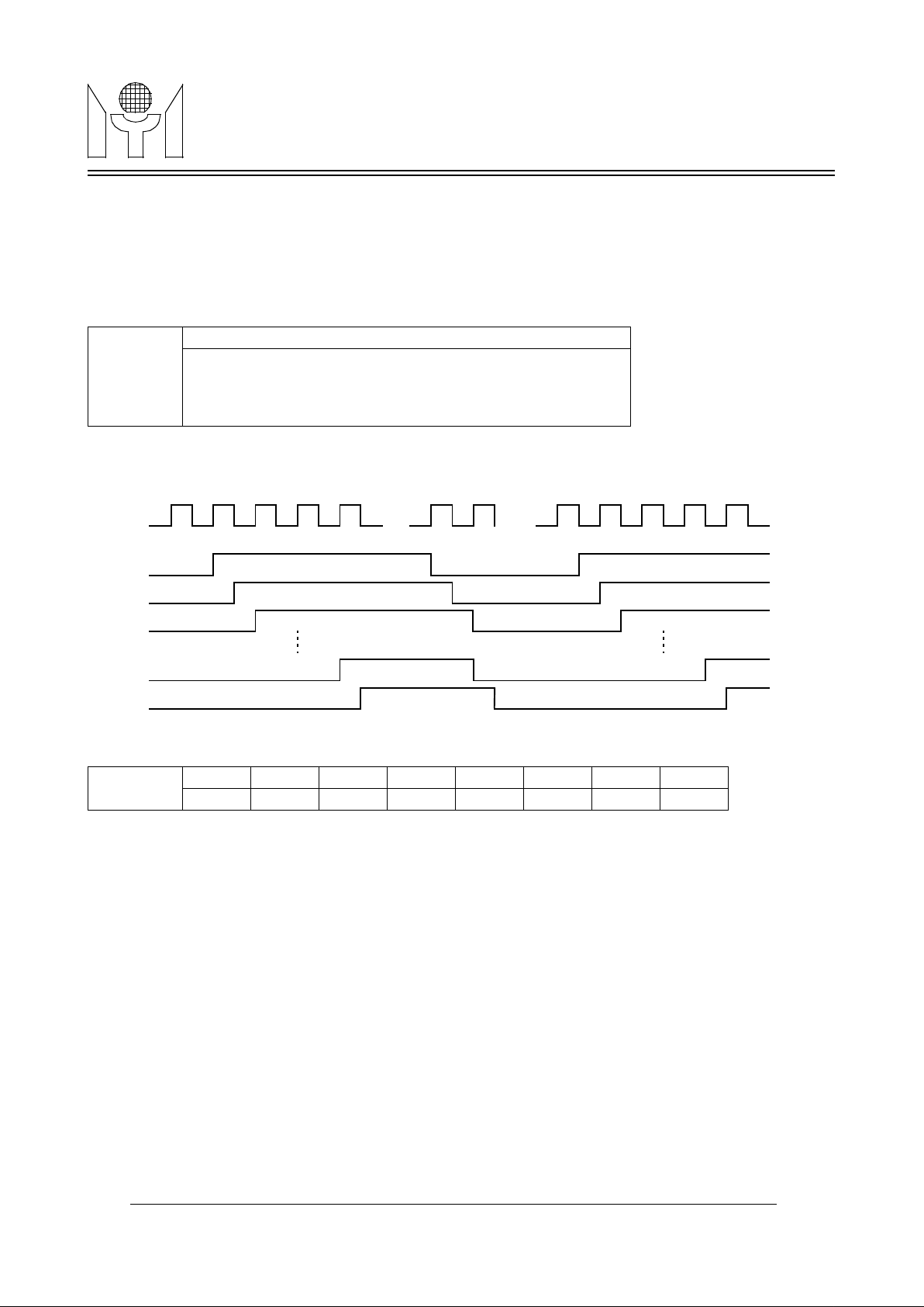
3.11 PWM D/A converter
There are 8 open-drain PWM D/A outputs (PWM0 to PWM7). These PWM D/A converter outputs pulse width
are programmable by writing data to Column 19 to 26 registers of Row 15 with 8-bit resolution to control the
pulse width duration from 0/256 to 255/256. And the sampling rate is selected by (PWM1, PWM0) shown as
table 5. In applications, all open-drain output pins should be pulled-up by external resistors to supply voltage
(5V to 9V) for desired output range.
PWMDA0 - PWMDA7 - Define the output pulse width of pin PWM0 to PWM7.
FIGURE 7. 8 Channel PWM Output Rising Edges Are Separated by Half PWMCK
Note: The byte is reserved for the testing. Write “ Ax ” will enter into test mode and write “ 00 ” in
normal operation.
4.0 ABSOLUTE MAXIMUM RATINGS
DC Supply Voltage(VDD) -0.3 to +7 V
Voltage with respect to Ground -0.3 to VDD+0.3 V
Storage Temperature -65 to +150 oC
Ambient Operating Temperature 0 to +70 oC
5.0 OPERATING CONDITIONS
DC Supply Voltage(VDD) +4.75 to +5.25 V
Operating Temperature 0 to +70 oC
Column 23
|
Column 30
b7 b6 b5 b4 b3 b2 b1 b0
PWMDA0
|
PWMDA7
MSB LSB
Column 31
B7 b6 b5 b4 b3 b2 b1 b0
0 0 0 0 0 0 0 0
255
0 1
2 3 255
0 1
2 3
m m+1
PWMCK
PWM0
PWM1
PWM2
PWM6
PWM7
Page 14
14/18 MTV121 Revision 5.0 06/29/1999
MTV121MYSON
TECHNOLOGY
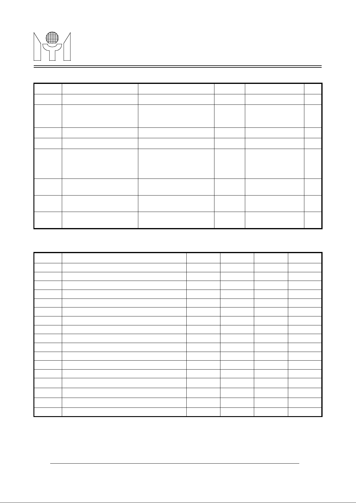
6.0 ELECTRICAL CHARACTERISTICS (Under Operating Conditions)
7.0 SWITCHING CHARACTERISTIC (Under Operating Conditions)
Symbol Parameter Conditions (Notes) Min. Max. Units
V
IH
Input High Voltage - 0.7 * VDD VDD+0.3 V
V
IL
Input Low Voltage - VSS-0.3
0.3 * VDD
(0.2 * VDD for SSB
pin)
V
V
OH
Output High Voltage
I
OH
≥ -5 mA
VDD-0.8 - V
V
OL
Output Low Voltage
IOL ≤ 5 mA
- 0.5 V
V
ODH
Open Drain Output High
Voltage
-
(For all OD pins, and pulled
up by external 5 to 9V
power supply)
5 9 V
V
ODL
Open Drain Output Low
Voltage
5 mA ≥ I
DOL
( For all OD pins )
- 0.5 V
I
CC
Operating Current
Pixel rate=96MHz
I
load = 0uA
- 25 mA
I
SB
Standby Current
Vin = VDD,
I
load = 0uA
- 12 mA
Symbol Parameter Min. Typ. Max. Units
f
HFLB
HFLB input frequency 15 - 130 KHz
T
r
Output rise time - - 5 ns
T
f
Output fall time - - 5 ns
t
BCSU
SSB to SCK set up time 200 - - ns
t
BCH
SSB to SCK hold time 100 - - ns
t
DCSU
SDA to SCK set up time 200 - - ns
t
DCH
SDA to SCK hold time 100 - - ns
t
SCKH
SCK high time 500 - - ns
t
SCKL
SCK low time 500 - - ns
t
SU:STA
START condition setup time 500 - - ns
t
HD:STA
START condition hold time 500 - - ns
t
SU:STO
STOP condition setup time 500 - - ns
t
HD:STO
STOP condition hold time 500 - - ns
t
SETUP
HFLB delay to rising edge of pixel clock 2 6 ns
t
HOLD
minimum pulse width of HFLB 25 ns
t
pd
propagation delay of output to pixel clock 10 ns
PIXin pixel clock input 6 96 MHz
Page 15
15/18 MTV121 Revision 5.0 06/29/1999
MTV121MYSON
TECHNOLOGY
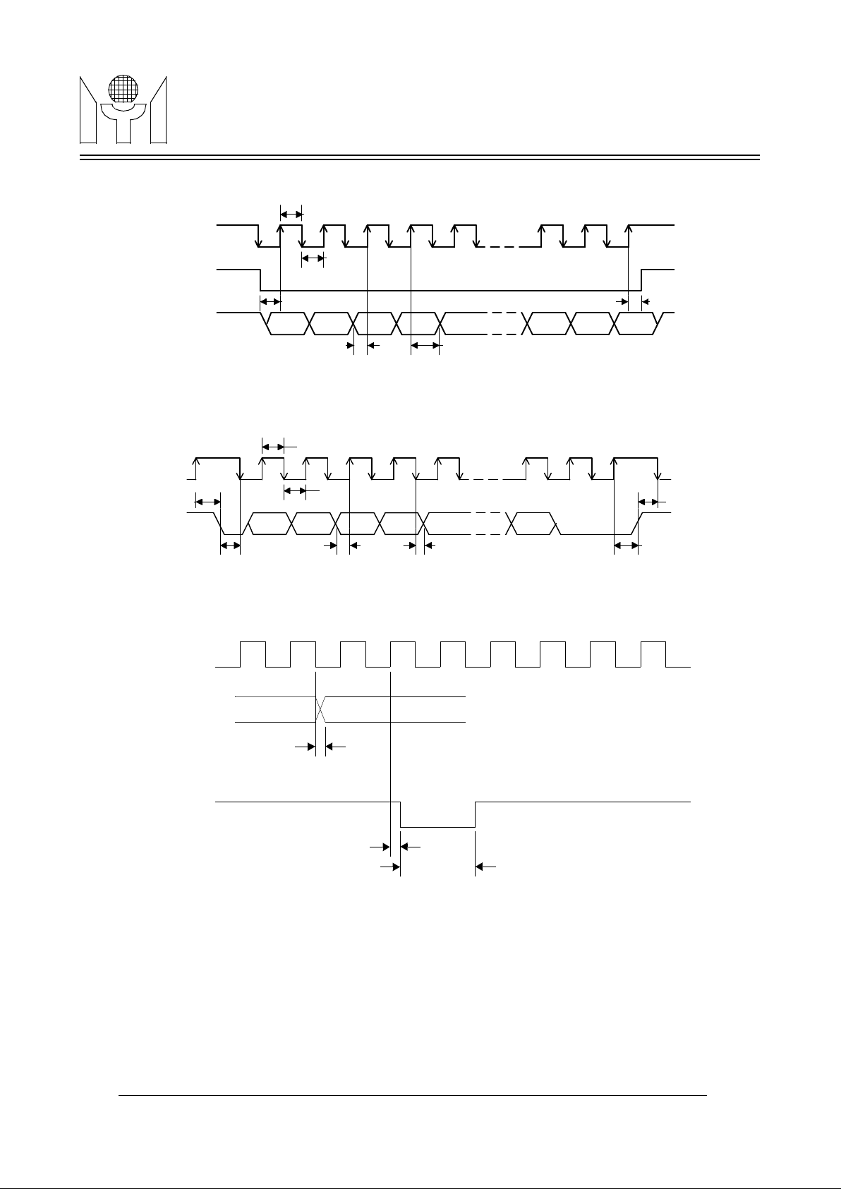
8.0 TIMING DIAGRAMS
FIGURE 8. Data interface timing(SPI)
SCK
SSB
SDA
t
SCKL
t
SCKH
t
BCSU
t
DCSU
t
DCH
t
BCH
SCK
SDA
t
SU:STA
t
SCKH
t
HD:STA
t
SCKL
t
DCSU
t
DCH
t
SU:STO
t
HD:STO
FIGURE 9. Data interface timing(I2C)
PlXin
R,G,B, FBKG
HTONE
t
pd
t
pd:: Propagation Delay to R,G,B, FBKG
and HTONE outputs
SETUP
t
HOLD
t
HFLB
FIGURE 10. Output and HFLB Timing to Pixel Clock
Page 16
16/18 MTV121 Revision 5.0 06/29/1999
MTV121MYSON
TECHNOLOGY
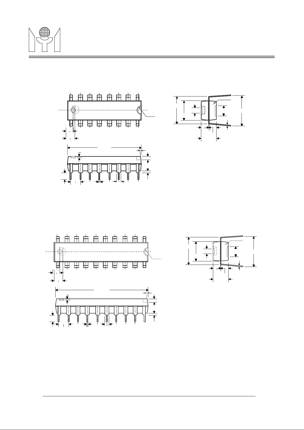
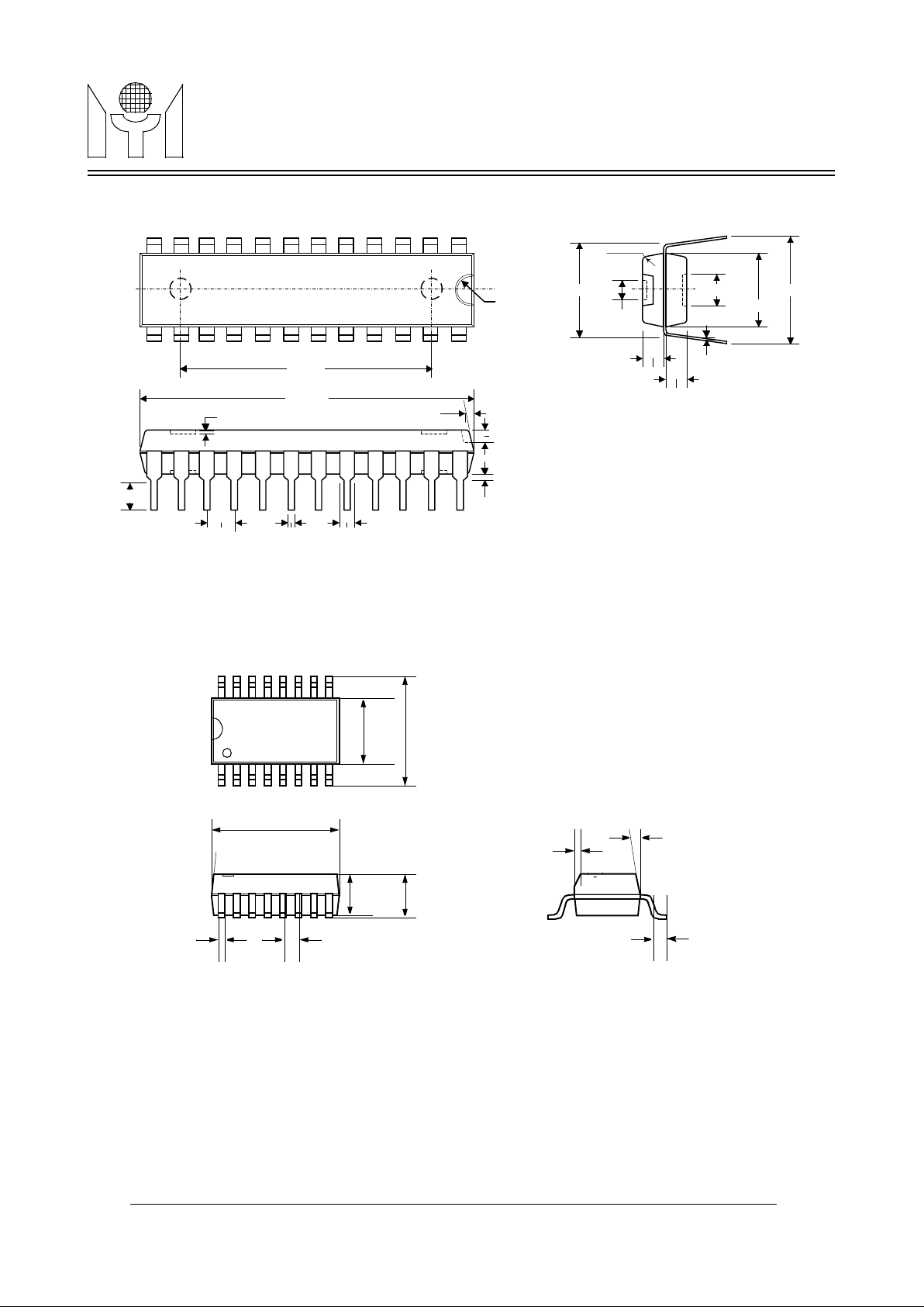
9.0 PACKAGE DEMENSION
9.1 16 Pin PDIP 300mil
9.2 20 Pin PDIP 300mil
75 +/-20
90 +/-20
250 +/-4
55 +/-20
90 +/-20
312 +/-12
65 +/-4
55 +/-4
310Max
350 +/-20
10
R10Max
(4X
)
100Ty
p
18 +/-
2Typ
60 +/5Typ
115 Min
750 +/-10
15 Min
35 +/-5
7
Typ
R40
15 Max
75 +/-20
90 +/-20
250 +/-4
55 +/-20
90 +/-20
312 +/-12
65 +/-4
55 +/-4
310Max
350 +/-20
10
R10Max
(4X
)
100Typ 18 +/-2Typ
60 +/-5Typ
115 Min
1020 +/-10
15 Min
35 +/-5
7
Typ
15 Max
R40
Page 17
17/18 MTV121 Revision 5.0 06/29/1999
MTV121MYSON
TECHNOLOGY
9.3 24 Pin PDIP 300mil
9.4 16 Pin SOP 300mil
930+/-10
R40
55+/-20
312+/-12
R10Max
(4X)
80+/-20
250+/-4
350+/-20
10
18+/2Typ
60+/5Typ
15Min.
15Max
115Min
100Ty
p
35+/-5
7Ty
p
1245+/-10
65+/-4
65+/-4
0.015x45
o
7o(4x)
0.028 +0.022 /-0.013
0.295 +/-0.004
0.406 +/-0.013
0.406 +/-0.008
0.016 +/-0.004 0.050
0.098 +/-0.006
0.091
(4x)
Page 18
18/18 MTV121 Revision 5.0 06/29/1999
MTV121MYSON
TECHNOLOGY
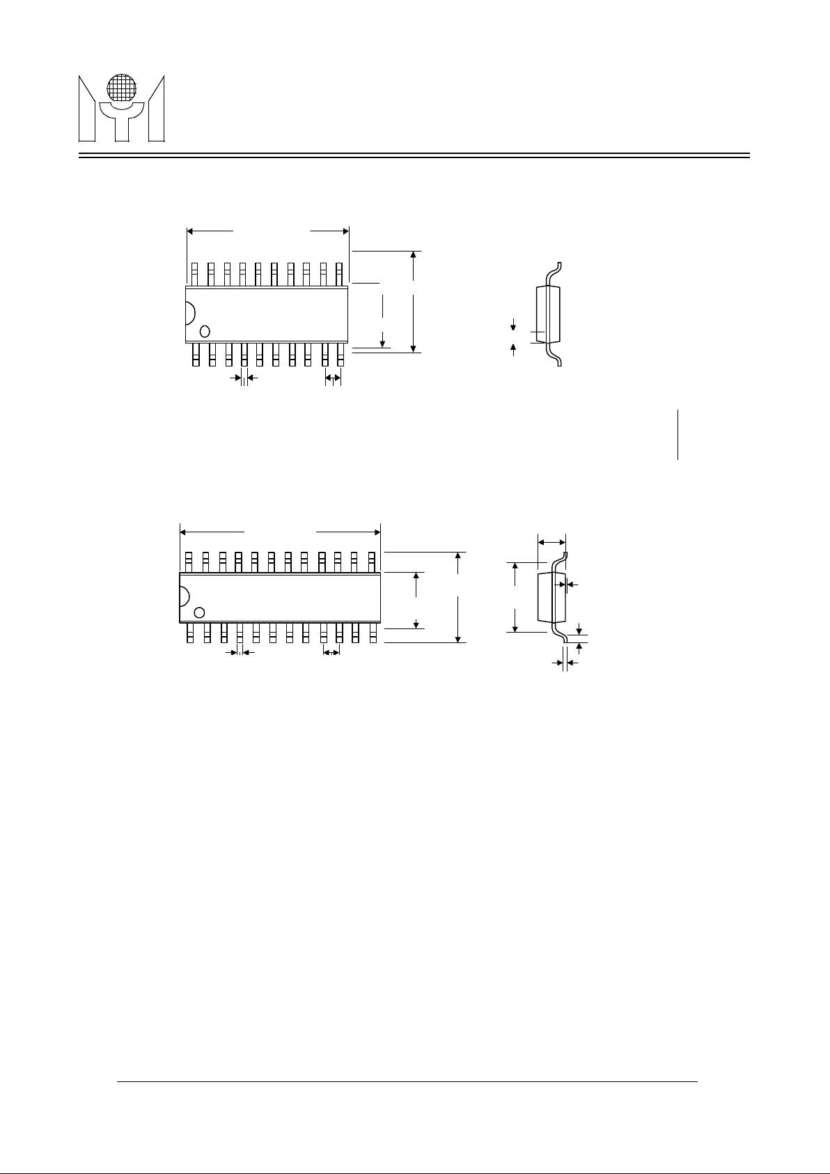
9.5 20 Pin SOP 300 mil
9.6 24 Pin SOP 300mil
10.0 CHARACTERS AND SYMBOLS PATTERN
Please see the attachment.
0.016typ. 0.050typ.
10
1
20 11
0.295+/-0.004inch
0.406+/-0.012inch
0.020x45
0.45mm +/-
0.1
15.0mm /+0.4 -0.1
1.27m
m
12
1
24
13
5.3mm +0.3/-
0.1
7.9mm+/-
0.4
6.9m
m
0.2mm
+0.1/-0.05
0.5mm+/-0.2
0.1mm +0.2/-0.05
1.85mm/+0.4 -0.15
Myson Technology USA, Inc.
http://www.myson.com
20111 Stevens Creek Blvd. #138 Cupertino, Ca. 95014, U.S.A.
Tel:408-252-8788 FAX: 408-252-8789 [email protected]
Myson Technology, Inc.
http://www.myson.com.tw
No. 2, Industry E. Rd. III, Science-Based Industrial Park, Hsinchu, Taiwan, R. O. C.
Tel: 886-3-5784866 Fax: 886-3-5785002
 Loading...