

Page 1
without notice. No liability is assumed as a result of the use of this procuts. No rights under any patent accompany the sales o
MTD658EMYSON
GENERAL DESCRIPTION
Provide 2 inter_repeater stacking bus for 10M
Build_in 2 port switch controller, support up to
no need any external memory buffers.
The build_in 2 port switch, support 2k MAC
addresses filtering, and use embedded asynchro-
nous high speed SRAM (64k*8) for packet buffer-
TECHNOLOGY
5/8 Port 10/100 Hub Build_in Bridge And Memory
FEATURES
• IEEE802.3 Clause 9 and IEEE802.3u Cluse 27
compliant.
• Provide 8 RMII (8 port mode), or 4 RMII + 1 MII
(5 port mode).
•
and 100M port expansion each.
• Support stacking to 4 units without any external
arbitration logic ( if use external arbitration
logic, theoretically can stack to 6 units and up) .
•
2048 MAC addresses filtering database.
• Optional back_pressure flow control.
• Optional up_link_switch port function (in slave
hub), support 100FX 2km distance extension in
100FD mode.
• Meet Class_2 repeater specification for
100M_hub.
• Pin compatible with MTD658/655 application,
• 128 pin QFP package, 3.3V operation voltage.
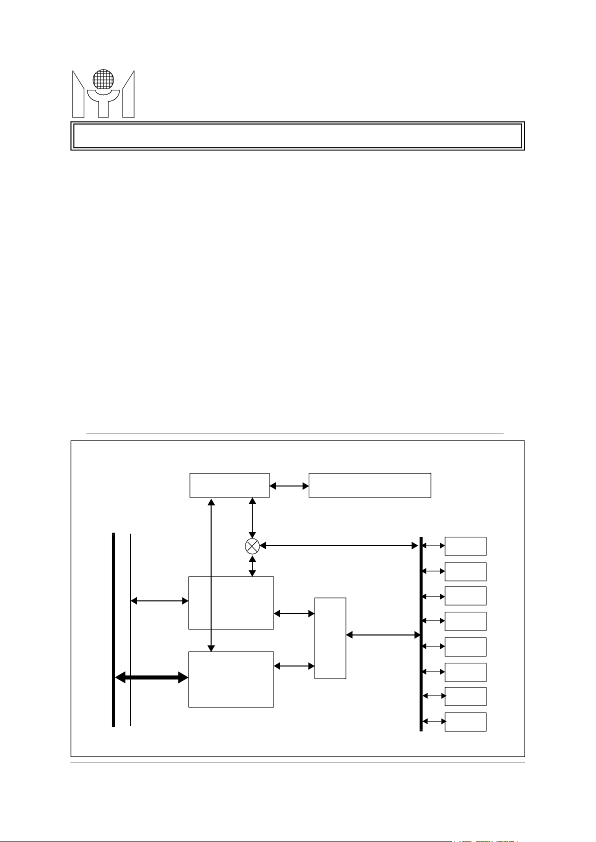
BLOCK DIAGRAM
The MTD658E is a highly integrated, 10M/
100M dual speed hub with build_in 2 port switch
and 64k8 embedded ASRAM. Support 8 RMII
ports for 10M/100M operation, and really meet
100M_hub class_2 spec when connect with
external QPHYceivers.
The MTD658E provides two Inter-repeater
stacking bus for 10M and 100M expansion each,
easily stack to 4 units without any external arbitration logic. If using external arbitration logic and
proper bus driver, can stack to 6 units and up.
ing. This 2 port switch can also be configured to
be up_link switch when hub is under slave mode.
The MTD658E also support an simple and
effective LED display function, provide 10M_col,
100M_col, and per port’s partition status.
10M
Inter Hub Bus
Two Port
Switch
10M
Uplin k Switch Enable(10/100,FD/HD)
10M_HD
Embedded 64k8 ASRAM
RMII7
RMII6
RMII5
Hub
RMII4
RMII3
RMII2
100M
Inter Hub Bus
100M_HD
100M
Port
Switch
Logic
Hub
RMII1
RMII0
This datasheet contains new product information. Myson Technology reserves the rights to modify the product specification
the product.
1/23 MTD658E Revision 1.1 05/25/2000
f
Page 2
without notice. No liability is assumed as a result of the use of this procuts. No rights under any patent accompany the sales o
TECHNOLOGY
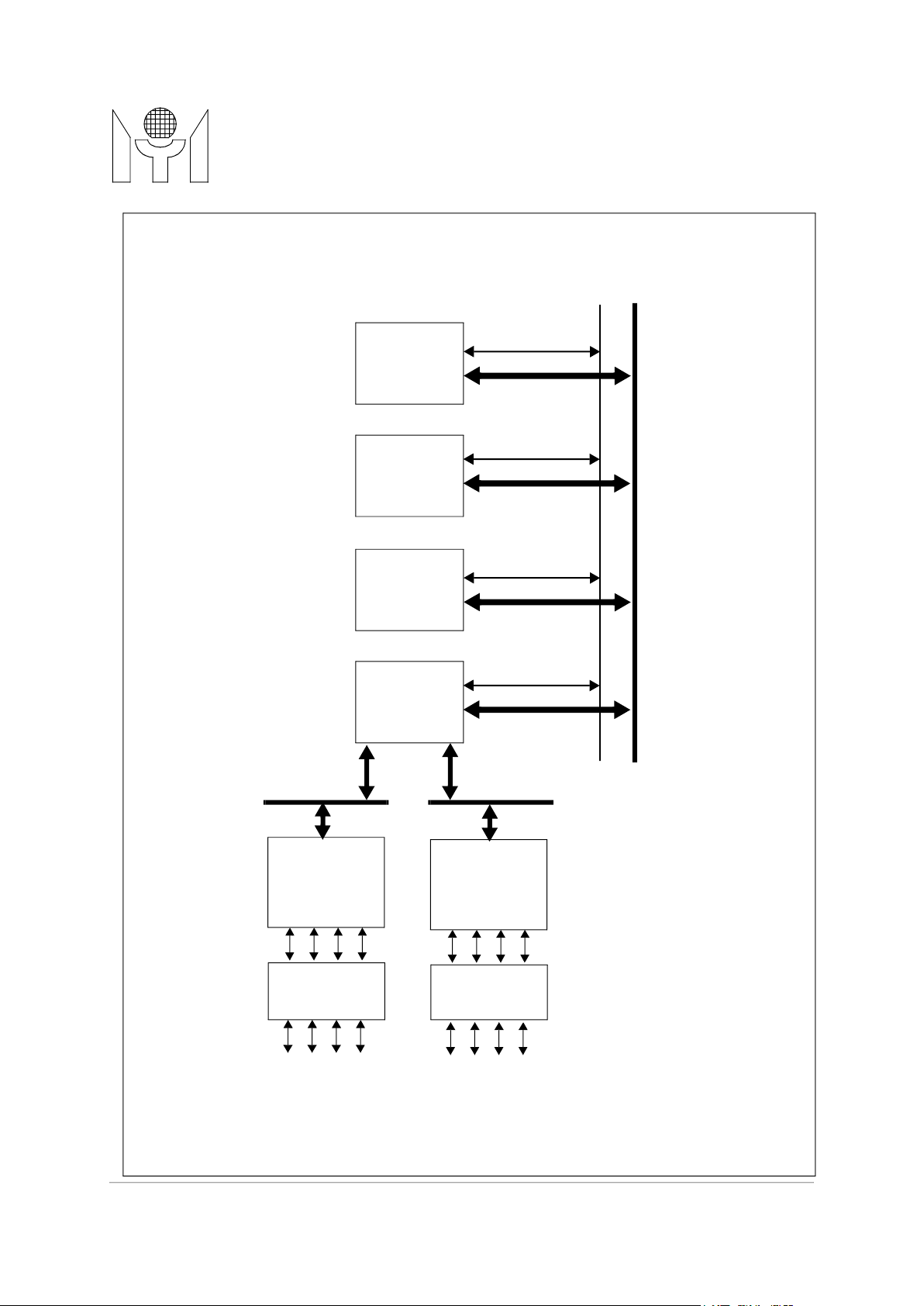
SYSTEM DIAGRAM
Transformer
MTD658E
MTD658E
DB25 Connector
10M
Inter Hub Bus
100M
Inter Hub Bus
10M
Inter Hub Bus
100M
Inter Hub Bus
10M
Inter Hub Bus
MTD658EMYSON
RMII0-3
QUAD
PHYsceiver
QUAD
Transformer
MTD658E
MTD658E
100M
Inter Hub Bus
10M
Inter Hub Bus
100M
Inter Hub Bus
RMII4-7
QUAD
PHYsceiver
QUAD
RJ45
This datasheet contains new product information. Myson Technology reserves the rights to modify the product specification
the product.
RJ45
2/23 MTD658E Revision 1.1 05/25/2000
f
Page 3

MTD658E Revision 1.1 05/25/2000
TECHNOLOGY
MTD658E
1.0 PIN CONNECTION (for 8 port mode)
PART4
PART5
PART6
PART7
RXACT0
RXACT1
RXACT2
RXACT3
RXACT4
RXACT5
GND
RXACT6
RXACT7
IREQ10_OUT
IREQ10_IN0
IREQ10_IN1
IREQ10_IN2
102
101
10099989796959493929190898887868584838281807978777675747372717069686766
VCC
PART3
GND
PART2
PART1
PART0
XCOL100
XCOL10
NC
NC
NC
CLK25OUT
NC
NC
GND
NC
NC
NC
VCC
SYSCLK
GND
LEDDAT
LEDCLK
MDC
MDIO
RSTB
103
104
105
106
107
108
109
110
111
112
113
114
115
116
117
118
119
120
121
122
123
124
125
126
127
128
(8 port mode)
MTD658EMYSON
ICOLB10
IACKB10
ICLK10
GND
IDAT10
IREQ100_OUT
IREQ100_IN0
IREQ100_IN1
IREQ100_IN2
ICOLB100
IACKB100
GND
ICLK100
VCC
IDAT100_0
IDAT100_1
IDAT100_2
IDAT100_3
IMASTER
FD7
UPSWEN
65
64
SPD4
63
SPD5
62
SPD6
61
SPD7
60
GND
59
VCC
58
RXD7_1
57
RXD7_0
56
TXEN7
55
TXD7_0
54
TXD7_1
53
CRSDV7
52
RXD6_1
51
RXD6_0
50
TXEN6
49
TXD6_0
48
TXD6_1
47
CRSDV6
46
GND
45
VCC
44
RXD5_1
43
RXD5_0
42
TXEN5
41
TXD5_0
40
TXD5_1
39
CRSDV5
01020304050607080910111213141516171819202122232425262728293031323334353637
CRSDV0
TXD0_1
VCC
TXD0_0
TXEN0
RXD0_0
RXD0_1
CRSDV1
TXD1_1
TXD1_0
TXEN1
RXD1_0
RXD1_1
GND
CRSDV2
TXD2_1
TXD2_0
TXEN2
RXD2_0
RXD2_1
CRSDV3
TXD3_1
TXD3_0
TXEN3
RXD3_0
RXD3_1
SPD3
SPD2
SPD1
SPD0
VCC
GND
CRSDV4
TXD4_1
TXD4_0
TXEN4
38
RXD4_0
RXD4_1
3/23
Page 4

MTD658E Revision 1.1 05/25/2000
TECHNOLOGY
MTD658E
2.0 PIN CONNECTION (for 5 port mode)
PART1
PART2
PART3
PART4NCNCNCRXACT0
RXACT1
RXACT2
GND
RXACT3
RXACT4
IREQ10_OUT
IREQ10_IN0
IREQ10_IN1
IREQ10_IN2
102
101
10099989796959493929190898887868584838281807978777675747372717069686766
VCC
PART0
GND
NC
NC
NC
XCOL100
XCOL10
NC
NC
NC
CLK25OUT
NC
NC
GND
NC
NC
NC
VCC
SYSCLK
GND
LEDDAT
LEDCLK
MDC
MDIO
RSTB
103
104
105
106
107
108
109
110
111
112
113
114
115
116
117
118
119
120
121
122
123
124
125
126
127
128
(5 port mode)
MTD658EMYSON
ICOLB10
IACKB10
ICLK10
GND
IDAT10
IREQ100_OUT
IREQ100_IN0
IREQ100_IN1
IREQ100_IN2
ICOLB100
IACKB100
GND
ICLK100
VCC
IDAT100_0
IDAT100_1
IDAT100_2
IDAT100_3
IMASTER
FD4
UPSWEN
65
64
SPD1
63
SPD2
62
SPD3
61
SPD4
60
GND
59
VCC
58
RXD4_1
57
RXD4_0
56
TXEN4
55
TXD4_0
54
TXD4_1
53
CRSDV4
52
RXD3_1
51
RXD3_0
50
TXEN3
49
TXD3_0
48
TXD3_1
47
CRSDV3
46
GND
45
VCC
44
RXD2_1
43
RXD2_0
42
TXEN2
41
TXD2_0
40
TXD2_1
39
CRSDV2
01020304050607080910111213141516171819202122232425262728293031323334353637
GNDNCVCCNCNC
GND
GND
SPD0
TXD0_3
TXD0_2NCTXCLK0
GND
GND
RXCLK0
TXD0_1
TXD0_0
TXEN0
RXD0_0
RXD0_1
GNDNCNCNCGND
GND
RXD0_2
RXD0_3
RXDV0
CRS0
VCC
GND
CRSDV1
TXD1_1
TXD1_0
TXEN1
38
RXD1_0
RXD1_1
4/23
Page 5
MTD658E Revision 1.1 05/25/2000
TECHNOLOGY
Port0 RMII receive interface signal, CRSDV0 is asserted high when
port0 media is non_idle.
Port0 RMII transmit enable signal.
Port0 RMII transmit data bit_0.
Port0 RMII transmit data bit_1.
Port1 RMII receive interface signal, CRSDV1 is asserted high when
port1 media is non_idle.
Port1 RMII transmit enable signal.
Port1 RMII transmit data bit_0.
Port1 RMII transmit data bit_1.
Port2 RMII receive interface signal, CRSDV2 is asserted high when
port2 media is non_idle.
Port2 RMII transmit enable signal.
Port2 RMII transmit data bit_0.
Port2 RMII transmit data bit_1.
Port3 RMII receive interface signal, CRSDV3 is asserted high when
port3 media is non_idle.
Port3 RMII transmit enable signal.
Port3 RMII transmit data bit_0.
Port3 RMII transmit data bit_1.
Port4 MII receive interface signal, CRSDV4 is asserted high when
port4 media is non_idle.
Port4 RMII transmit enable signal.
Port4 RMII transmit data bit_0.
Port4 RMII transmit data bit_1.
Port5 RMII receive interface signal, CRSDV5 is asserted high when
port5 media is non_idle.
Port5 RMII transmit enable signal.
Port5 RMII transmit data bit_0.
Port5 RMII transmit data bit_1.
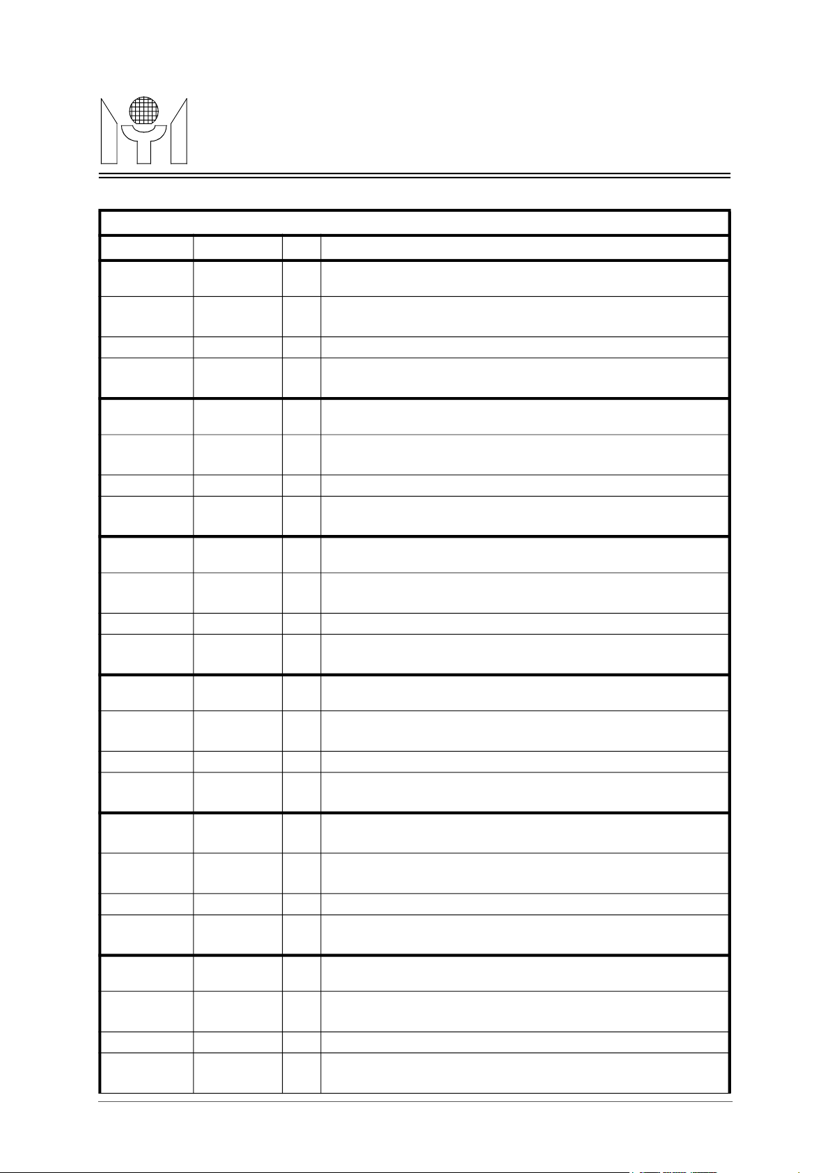
3.0 PIN DESCRIPTIONS (for 8 port mode)
RMII Port Interface Pins (for 8 port mode)
Name Pin Number I/O Descriptions
CRSDV0
1
I
MTD658EMYSON
RXD0_0
RXD0_1
TXEN0
TXD0_0
TXD0_1
CRSDV1
RXD1_0
RXD1_1
TXEN1
TXD1_0
TXD1_1
CRSDV2
RXD2_0
RXD2_1
TXEN2
TXD2_0
TXD2_1
CRSDV3
6
7
5
4
2
8
12
13
11
10
9
15
19
20
18
17
16
21
IIPort0 RMII receive data bit_0.
Port0 RMII receive data bit_1.
O
O
O
I
IIPort1 RMII receive data bit_0.
Port1 RMII receive data bit_1.
O
O
O
I
IIPort2 RMII receive data bit_0.
Port2 RMII receive data bit_1.
O
O
O
I
RXD3_0
RXD3_1
TXEN3
TXD3_0
TXD3_1
CRSDV4
RXD4_0
RXD4_1
TXEN4
TXD4_0
TXD4_1
CRSDV5
RXD5_0
RXD5_1
TXEN5
TXD5_0
TXD5_1
25
26
24
23
22
33
37
38
36
35
34
39
43
44
42
41
40
IIPort3 RMII receive data bit_0.
Port3 RMII receive data bit_1.
O
O
O
I
IIPort4 RMII receive data bit_0.
Port4 RMII receive data bit_1.
O
O
O
I
IIPort5 RMII receive data bit_0.
Port5 RMII receive data bit_1.
O
O
O
5/23
Page 6
MTD658E Revision 1.1 05/25/2000
TECHNOLOGY
Port6 RMII receive interface signal, CRSDV6 is asserted high when
port6 media is non_idle.
Port6 RMII transmit enable signal.
Port6 RMII transmit data bit_0.
Port6 RMII transmit data bit_1.
Port7 RMII receive interface signal, CRSDV7 is asserted high when
port7 media is non_idle.
Port7 RMII transmit enable signal.
Port7 RMII transmit data bit_0.
Port7 RMII transmit data bit_1.
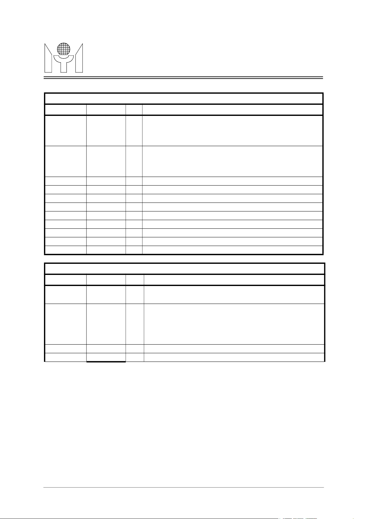
when high: means hub internal inter_bus arbiter is enabled and hub
when low: means hub internal inter_bus arbiter is disabled and hub
10M Inter-Bus port access acknowledge signal (low active). For master
hub, this pin is output; for slave hub is input, or while EXT_ARB
jumper was set to high, this pin is input from an external arbitration
10M Inter-Bus collision signal (low active). For master hub, this pin can
this pin is an input, or while EXT_ARB jumper was set to high, this pin
is input from an external arbitration device.
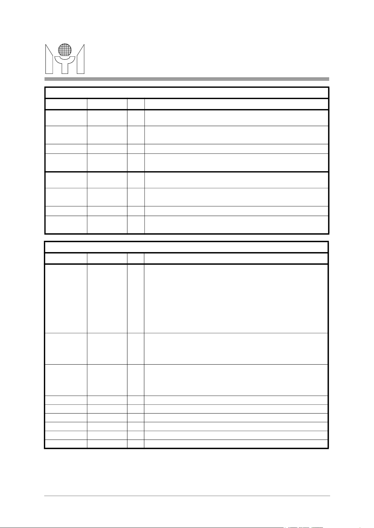
RMII Port Interface Pins (for 8 port mode)
Name Pin Number I/O Descriptions
CRSDV6
47
I
MTD658EMYSON
RXD6_0
RXD6_1
TXEN6
TXD6_0
TXD6_1
CRSDV7
RXD7_0
RXD7_1
TXEN7
TXD7_0
TXD7_1
Name Pin Number I/O Descriptions
IMASTER
51
52
50
49
48
53
57
58
56
55
54
67
IIPort6 RMII receive data bit_0.
Port6 RMII receive data bit_1.
O
O
O
I
IIPort7 RMII receive data bit_0.
Port7 RMII receive data bit_1.
O
O
O
10M Inter-Bus Interface pins (for 8 port mode)
I Master hub selection:
internal two_port switch is well conneted to 10M_hub core and
100M_hub core .
internal two_port switch is not connected to 10M_hub core and
100M_hub core.
IACKB10
84
ICOLB10
85
IREQ10_IN0 88 I 10M Inter-Bus port access request input.
IREQ10_IN1 87 I 10M Inter-Bus port access request input.
IREQ10_IN2 86 I 10M Inter-Bus port access request input.
IREQ10_OUT 89 O 10M Inter-Bus port access request output.
ICLK10 83 I/O 10M Inter-Bus port clock.
IDAT10 81 I/O 10M Inter-Bus port data bit
I/O
device.
I/O
output multi hub collision event to inform all slave hub ; for slave hub,
6/23
Page 7
MTD658E Revision 1.1 05/25/2000
TECHNOLOGY
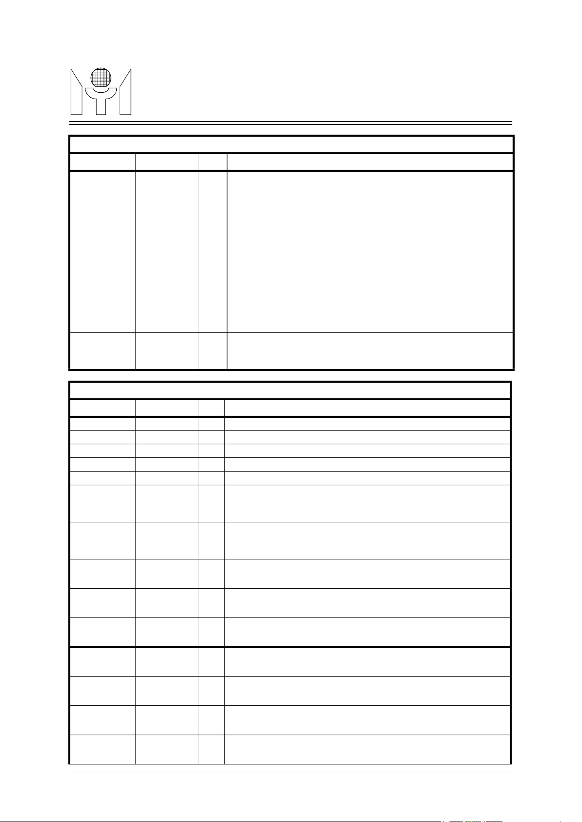
100M Inter-Bus port access acknowledge signal (low active). For master
hub, this pin is output; for slave hub is input, or while EXT_ARB
jumper was set to high, this pin is input from an external arbitration
can output multi hub collision event to inform all slave hub ; for slave
Port 7-0 Rx Activity LED Outputs, low_active.
Direct output per port receive activity status for LED display.
Port 7-0 Partition LED Outputs, low_active.
Direct output per port partition status for LED display. During power on
reset PART7 pin use as MII setting start PHY device ID selection. 4.7K
pull up resistor will set PHY device ID from 5h08 - 5h0f, no pull up 4.7k
100M Hub Collision LED Output, low_active.
10M Hub Collision LED Output, low_active.
100M Inter-Bus Interface pins (for 8 port mode)
Name Pin Number I/O Descriptions
IACKB100
75
ICOLB100
I/O
device.
I/O 100M Inter-Bus collision signal (low active). For master hub, this pin
MTD658EMYSON
76
IREQ100_IN0 79 I 100M Inter-Bus port access request input.
IREQ100_IN1 78 I 100M Inter-Bus port access request input.
IREQ100_IN2 77 I 100M Inter-Bus port access request input.
IREQ100_OUT 80 O 100M Inter-Bus port access request output.
ICLK100 73 I/O 100M Inter-Bus port clock.
IDAT100_0 71 I/O 100M Inter-Bus port data bit 0.
IDAT100_1 70 I/O 100M Inter-Bus port data bit 1.
IDAT100_2 69 I/O 100M Inter-Bus port data bit 2.
IDAT100_3 68 I/O 100M Inter-Bus port data bit 3.
Name Pin Number I/O Descriptions
RXACT7-0
PART7-0
XCOL100 109 I/O
XCOL10 110 I/O
90,91,93,94,
95,96,97,98
99,100,101,
102,104,106,
107,108
hub, this pin is an input, or while EXT_ARB jumper was set to high,
this pin is input from an external arbitration device.
LED Interface Pins (for 8 port mode)
I/O
I/O
resistor will set PHY device ID from 5h04 -5h0b.
7/23
Page 8
MTD658E Revision 1.1 05/25/2000
TECHNOLOGY
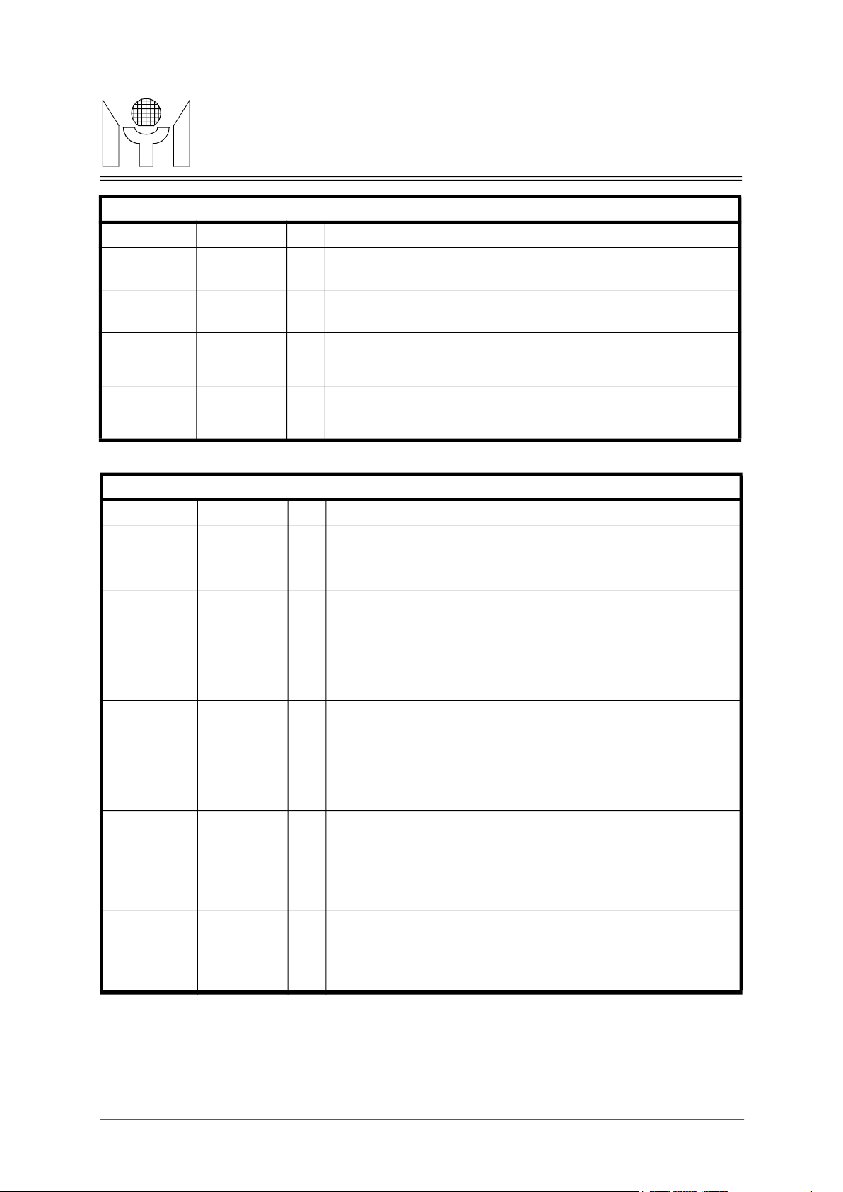
LED display serial data out, high_active; mapping for LEDCLK sig-
is from b00, and end of burst bit is b23)
b02: port2 partition b10: asram_test_fail b18: port2 rx_activity
b03: port3 partition b11: port3 partition b19: port3 rx_activity
LED display clock signal; the signal is a discontinued clock for LED
data serial shift out. Every clock burst have 24 cycles ( period : 160 ns),
System reset input, low active.
50MHz system clock input.
MII management clock inout.
MII management data inout.
Up_link switch port enabling : one of internal two_port switch port will
connect to 100M_hub domain, and another port will redirect to RMII
When up_link switch port enabling, this pin is port7’s full_deplex indi-
cator, input from PHY. When hign , indicate port7 in running on
Port0 speed indicator, input from PHY.
SPD0 input low: 100M , input high: 10M.
Port1 speed indicator, input from PHY.
SPD1 input low: 100M , input high: 10M.
Port2 speed indicator, input from PHY.
SPD2 input low: 100M , input high: 10M.
Port3 speed indicator, input from PHY.
SPD3 input low: 100M , input high: 10M.
Port4 speed indicator, input from PHY.
SPD4 input low: 100M , input high: 10M.
Port5 speed indicator, input from PHY.
SPD5 input low: 100M , input high: 10M.
Port6 speed indicator, input from PHY.
SPD6 input low: 100M , input high: 10M.
LED Interface Pins (for 8 port mode)
Name Pin Number I/O Descriptions
LEDDAT
124
LEDCLK
125
I/O
nal’s burst clock , its serial out data sequence is : ( first bit be shifted out
b00: port0 partition b08: 10hub_col b16: port0 rx_activity
b01: port1 partition b09: 100hub_col b17: port1 rx_activity
b04: port4 partition b12: port4 partition b20: port4 rx_activity
b05: port5 partition b13: port5 partition b21: port5 rx_activity
b06: port6 partition b14: port6 partition b22: port6 rx_activity
b07: port7 partition b15: port7 partition b23: port7 rx_activity
I/O
and the clock burst will be repeated with every 42ms.
MTD658EMYSON
Miscellaneous Pins (for 8 port mode)
Name Pin Number I/O Descriptions
RSTB 128 I
SYSCLK 122 I
CLK25MOUT 114 I/O 25MHz clock output.
MDC 126 I/O
MDIO 127 I/O
UPSWEN
FD7
SPD0
SPD1
SPD2
SPD3
65
66
30
29
28
27
I
port7.
I
full_duplex mode. When low, indicate on half_duplex mode.
I
I
I
I
SPD4
SPD5
SPD6
64
63
62
I
I
I
8/23
Page 9
MTD658E Revision 1.1 05/25/2000
TECHNOLOGY
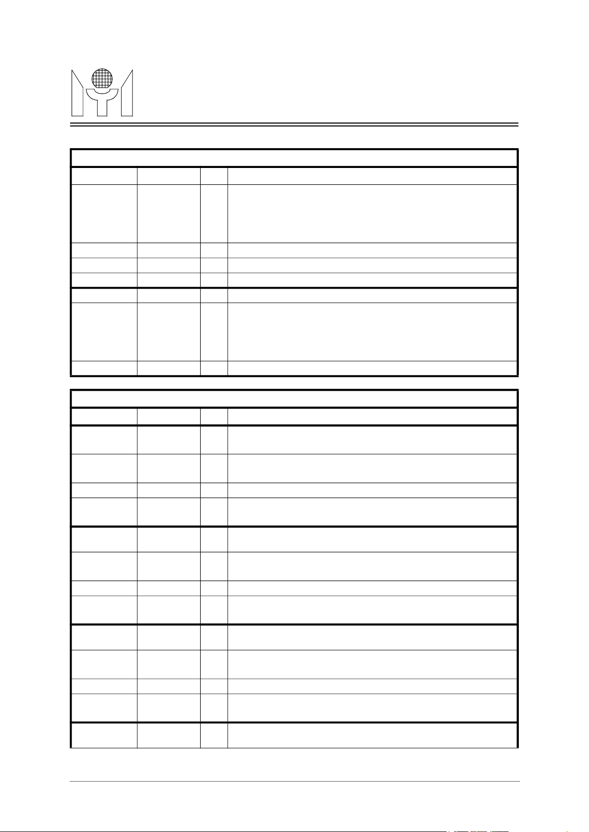
Port7 speed indicator, input from PHY.
SPD7 input low: 100M , input high: 10M.
- external pull_low (default ) : normal mode (back_pressure enbale)
Auto MII_setting bypass : ( power on external jumper configuration )
- external pull_low (default ) : normal mode ( auto MII_setting); after
power_on, MTD658E will auto setup PHY devices be forced in half_
duplex mode for repeater apllication.
- external pull_low (default ) : MII setting PHY_ID start address from
- external pull_high: MII setting PHY_ID start address from
1522 bytes packet accept enable : ( power on external jumper configura-
- external pull_low (default ) : normal mode ( <=1518 bytes packet
- external pull_high: <= 1522 bytes packet accept
- external pull_low (default ) : normal mode (inter_repeater bus use
Miscellaneous Pins (for 8 port mode)
Name Pin Number I/O Descriptions
SPD7
61
I
MTD658EMYSON
VCC 3,31,45,59,
72,103,121
GND 14,32,46,60,
74,82,92,105
,117,123
NC_pin 111,112,113,
115,116,118,
119,120
Power On Configuration Set Up Table (for 8 port mode)
Name Pin Number I/O Descriptions
TXEN2
18
TXEN5
42
PART7
PWR Power pins
GND Ground pins
NC No connection pins
I/O Back_pressure disable : ( power on external jumper configuration )
- external pull_high: back_pressure disable
I/O
- external pull_high: auto MII_setting bypass
I/O PHY_ID 5h8 starting enable :(power on external jumper configuration)
MDC
LEDDAT
99
126
124
5h04 to 5h0b.
5h08 to 5h0f.
I/O
tion )
accept)
I/O External arbiter enable : ( power on external jumper configuration )
internal arbiter)
- external pull_high: inter_repeater bus use external arbiter .
9/23
Page 10
MTD658E Revision 1.1 05/25/2000
TECHNOLOGY
Port0 MII asynchronous carrier indicator from PHY device.
Port0 MII synchronous receive data valid signal from PHY device.
Port0 MII transmit enable signal.
Port0 MII transmit data bit_0.
Port0 MII transmit data bit_1.
Port0 MII transmit data bit_2.
Port0 MII transmit data bit_3.
Port0 MII transmit clock.
Port1 RMII receive interface signal, CRSDV1 is asserted high when
port1 media is non_idle.
Port1 RMII transmit enable signal.
Port1 RMII transmit data bit_0.
Port1 RMII transmit data bit_1.
Port2 RMII receive interface signal, CRSDV2 is asserted high when
port2 media is non_idle.
Port2 RMII transmit enable signal.
Port2 RMII transmit data bit_0.
Port2 RMII transmit data bit_1.
Port3 RMII receive interface signal, CRSDV3 is asserted high when
port3 media is non_idle.
Port3 RMII transmit enable signal.
Port3 RMII transmit data bit_0.
Port3 RMII transmit data bit_1.
Port4 RMII receive interface signal, CRSDV4 is asserted high when
port4 media is non_idle.
4.0 PIN DESCRIPTIONS (for 5 port mode)
MII Port (port0) Interface Pins (for 5 port mode)
Name Pin Number I/O Descriptions
RXD0_0
RXD0_1
RXD0_2
RXD0_3
CRS0
RXDV0
RXCLK0
TXEN0
TXD0_0
TXD0_1
TXD0_2
TXD0_3
TXCLK0
19
20
27
28
30
29
15
18
17
16
10
9
12
I
Port0 MII receive data bit_0.
I
Port0 MII receive data bit_1.
I
Port0 MII receive data bit_2.
I
Port0 MII receive data bit_3.
I
I
I Port0 MII receive clock.
O
O
O
O
O
I
MTD658EMYSON
RMII Port (port1~port4) Interface Pins (for 5 port mode)
Name Pin Number I/O Descriptions
CRSDV1
RXD1_0
RXD1_1
TXEN1
TXD1_0
TXD1_1
CRSDV2
RXD2_0
RXD2_1
TXEN2
TXD2_0
TXD2_1
CRSDV3
RXD3_0
RXD3_1
TXEN3
TXD3_0
TXD3_1
CRSDV4
33
37
38
36
35
34
39
43
44
42
41
40
47
51
52
50
49
48
53
I
IIPort1 RMII receive data bit_0.
Port1 RMII receive data bit_1.
O
O
O
I
IIPort2 RMII receive data bit_0.
Port2 RMII receive data bit_1.
O
O
O
I
IIPort3 RMII receive data bit_0.
Port3 RMII receive data bit_1.
O
O
O
I
10/23
Page 11
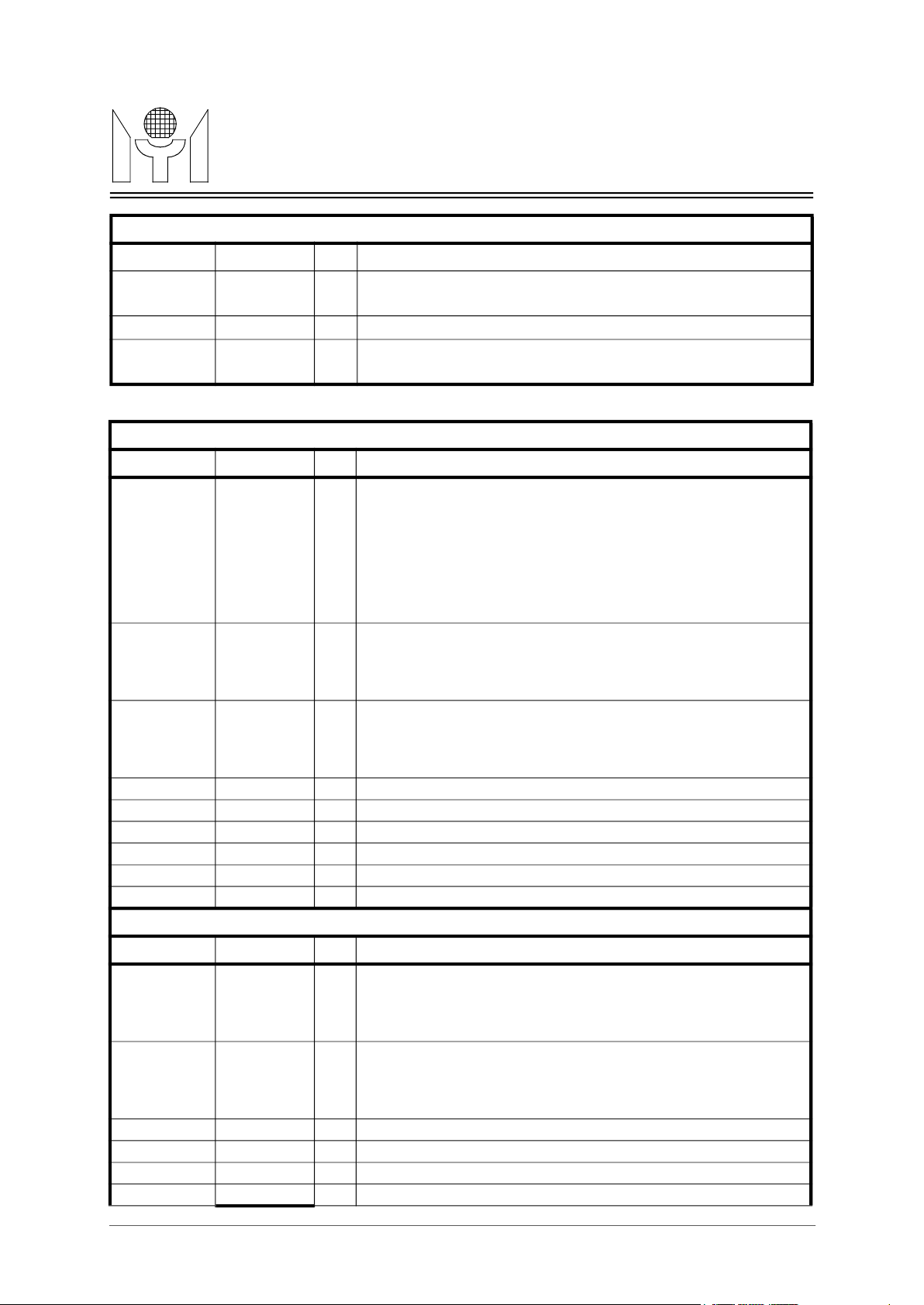
MTD658E Revision 1.1 05/25/2000
TECHNOLOGY
Port4 RMII transmit enable signal.
Port4 RMII transmit data bit_0.
Port4 RMII transmit data bit_1.
when high: means hub internal inter_bus arbiter is enabled and hub
when low: means hub internal inter_bus arbiter is disabled and hub
10M Inter-Bus port access acknowledge signal (low active). For master
hub, this pin is output; for slave hub is input, or while EXT_ARB
jumper was set to high, this pin is input from an external arbitration
10M Inter-Bus collision signal (low active). For master hub, this pin can
this pin is an input, or while EXT_ARB jumper was set to high, this pin
is input from an external arbitration device.
100M Inter-Bus port access acknowledge signal (low active). For master
hub, this pin is output; for slave hub is input, or while EXT_ARB
jumper was set to high, this pin is input from an external arbitration
can output multi hub collision event to inform all slave hub ; for slave
RMII Port (port1~port4) Interface Pins (for 5 port mode)
Name Pin Number I/O Descriptions
RXD4_0
RXD4_1
TXEN4
TXD4_0
TXD4_1
Name Pin Number I/O Descriptions
IMASTER
57
58
56
55
54
67
IIPort4 RMII receive data bit_0.
Port4 RMII receive data bit_1.
O
O
O
10M Inter-Bus Interface pins (for 5 port mode)
I Master hub selection:
internal two_port switch is well conneted to 10M_hub core and
100M_hub core .
MTD658EMYSON
internal two_port switch is not connected to 10M_hub core and
100M_hub core.
IACKB10
84
ICOLB10
85
IREQ10_IN0 88 I 10M Inter-Bus port access request input.
IREQ10_IN1 87 I 10M Inter-Bus port access request input.
IREQ10_IN2 86 I 10M Inter-Bus port access request input.
IREQ10_OUT 89 O 10M Inter-Bus port access request output.
ICLK10 83 I/O 10M Inter-Bus port clock.
IDAT10 81 I/O 10M Inter-Bus port data bit
Name Pin Number I/O Descriptions
IACKB100
75
ICOLB100
I/O
device.
I/O
output multi hub collision event to inform all slave hub ; for slave hub,
100M Inter-Bus Interface pins (for 5 port mode)
I/O
device.
I/O 100M Inter-Bus collision signal (low active). For master hub, this pin
76
IREQ100_IN0 79 I 100M Inter-Bus port access request input.
IREQ100_IN1 78 I 100M Inter-Bus port access request input.
IREQ100_IN2 77 I 100M Inter-Bus port access request input.
IREQ100_OUT 80 O 100M Inter-Bus port access request output.
hub, this pin is an input, or while EXT_ARB jumper was set to high,
this pin is input from an external arbitration device.
11/23
Page 12
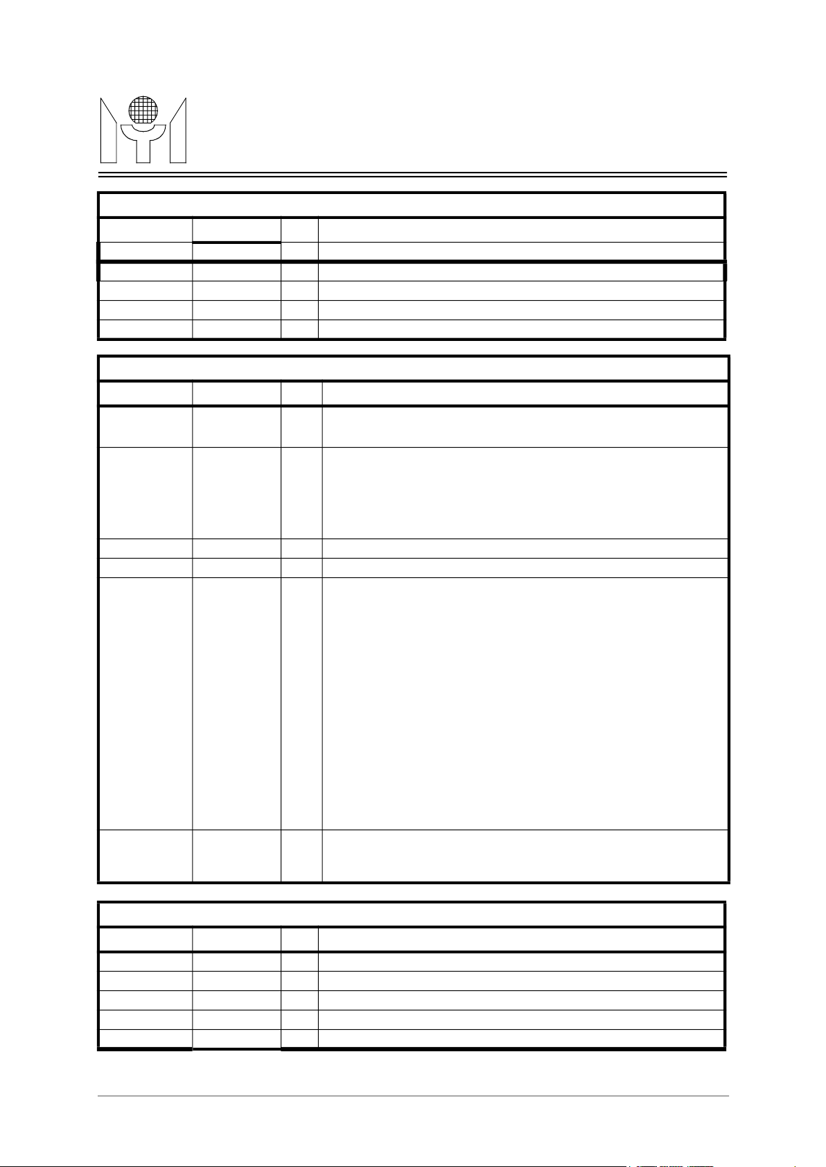
MTD658E Revision 1.1 05/25/2000
TECHNOLOGY
Port 4-0 Rx Activity LED Outputs, low_active.
Port 4-0 Partition LED Outputs, low_active.
Direct output per port partition status for LED display. During power on
reset PART4 pin use as MII setting start PHY device ID selection. 4.7K
pull up resistor will set PHY device ID from 5h08 - 5h0f, no pull up 4.7k
100M Hub Collision LED Output, low_active.
10M Hub Collision LED Output, low_active.
LED display serial data out, high_active; mapping for LEDCLK sig-
is from b00, and end of burst bit is b23)
b00: *********** b08: 10hub_col b16: ************
b01: ********** b09: 100hub_col b17: ************
b02: ********** b10: asram_test_fail b18: ************
b03: port0 partition b11: port0 partition b19: port0 rx_activity
LED display clock signal, the signal is a discontinued clock for LED
data serial shift out. Every clock burst have 24 cycles ( period : 160 ns),
System reset input, low active.
50MHz system clock input
MII management clock inout
MII management data inout
100M Inter-Bus Interface pins (for 5 port mode)
Name Pin Number I/O Descriptions
ICLK100 73 I/O 100M Inter-Bus port clock.
IDAT100_0 71 I/O 100M Inter-Bus port data bit 0.
IDAT100_1 70 I/O 100M Inter-Bus port data bit 1.
IDAT100_2 69 I/O 100M Inter-Bus port data bit 2.
IDAT100_3 68 I/O 100M Inter-Bus port data bit 3.
LED Interface Pins (for 5 port mode)
Name Pin Number I/O Descriptions
RXACT4-0
PART4-0
90,91,93,94,
95
99,100,101,
102,104
I/O
Direct output per port receive activity status for LED display.
I/O
MTD658EMYSON
XCOL100 109 I/O
XCOL10 110 I/O
LEDDAT
124
LEDCLK
125
I/O
I/O
Miscellaneous Pins (for 5 port mode)
resistor will set PHY device ID from 5h04 -5h0b.
nal’s burst clock , its serial out data sequence is : ( first bit be shifted out
b04: port1 partition b12: port1 partition b20: port1 rx_activity
b05: port2 partition b13: port2 partition b21: port2 rx_activity
b06: port3 partition b14: port3 partition b22: port3 rx_activity
b07: port4 partition b15: port4 partition b23: port4 rx_activity
and the clock burst will be repeated with every 42ms.
Name Pin Number I/O Descriptions
RSTB 128 I
SYSCLK 122 I
CLK25MOUT 114 I/O 25MHz clock output.
MDC 126 I/O
MDIO 127 I/O
12/23
Page 13
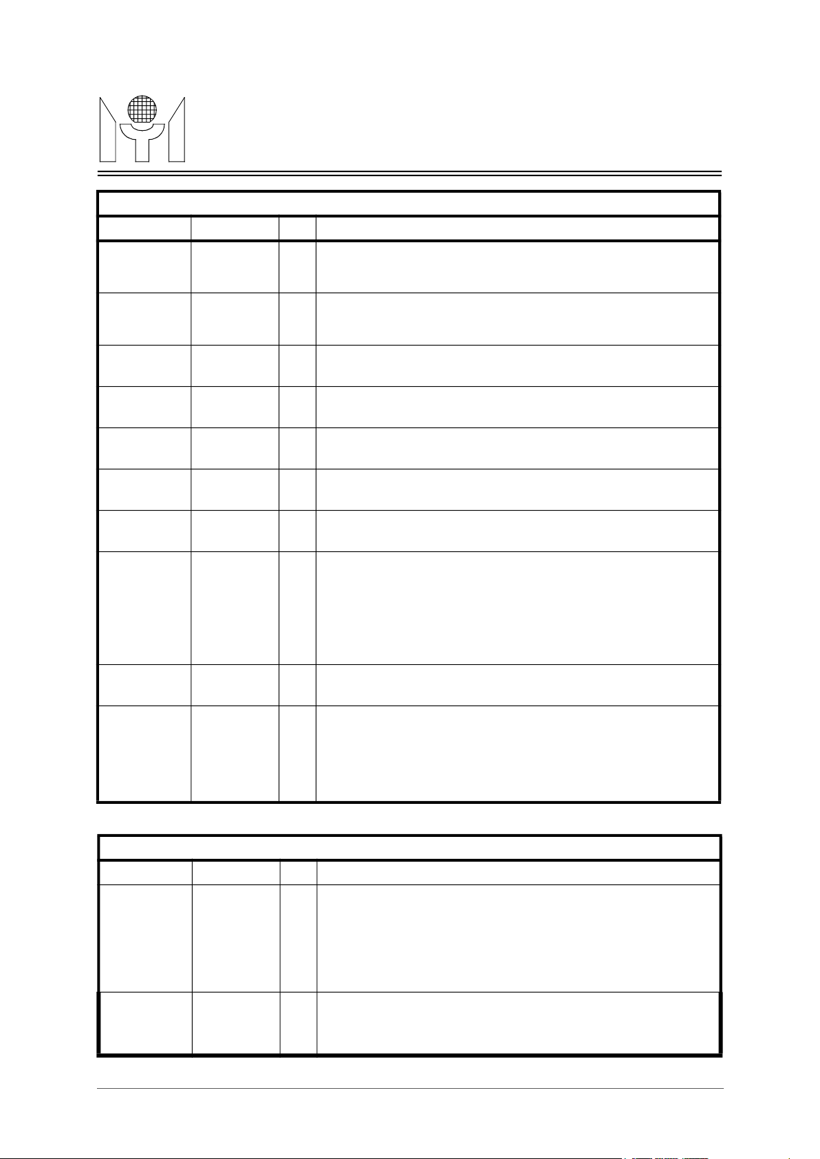
MTD658E Revision 1.1 05/25/2000
TECHNOLOGY
Up_link switch port enabling : one of internal two_port switch port will
connect to 100M_hub domain, and another port will redirect to RMII
When up_link switch port enabling, this pin is port4’s full_deplex indi-
cator, input from PHY. When hign , indicate port4 in running on
Port0 speed indicator, input from PHY.
SPD0 input low: 100M , input high: 10M.
Port1 speed indicator, input from PHY.
SPD1 input low: 100M , input high: 10M.
Port2 speed indicator, input from PHY.
SPD2 input low: 100M , input high: 10M.
Port3 speed indicator, input from PHY.
SPD3 input low: 100M , input high: 10M.
Port4 speed indicator, input from PHY.
SPD4 input low: 100M , input high: 10M.
Port0 MII interface enable : ( power on external jumper configuration )
- external pull_high: Port0 MII interface enable. (suitable for 5 port dual
- external pull_low (default ) : normal mode (back_pressure enbale)
Miscellaneous Pins (for 5 port mode)
Name Pin Number I/O Descriptions
UPSWEN
65
FD4
66
SPD0
8
I
port4.
I
full_duplex mode. When low, indicate on half_duplex mode.
I
MTD658EMYSON
SPD1
64
SPD2
63
SPD3
62
SPD4
61
NC_pin 2,4,5,11,22,
23,24,96,97,
98,106,107,
108,111,112,
113,115,116,
118,119,120
VCC 3,31,45,59,
72,103,121
GND 1,6,7,13,14,
21,25,26,32,
46,60,74,82,
92,105,117,
123
I
I
I
I
NC No connection pins
PWR Power pins
GND Ground pins
Power On Configuration Set Up Table (for 5 port mode)
Name Pin Number I/O Descriptions
NC_11
11
TXEN0
18
I/O
- pin floating : Port0 MII interface disable (Port0 : be configured in
RMII interface)
speed hub application).
I/O Back_pressure disable : ( power on external jumper configuration )
- external pull_high: back_pressure disable
13/23
Page 14
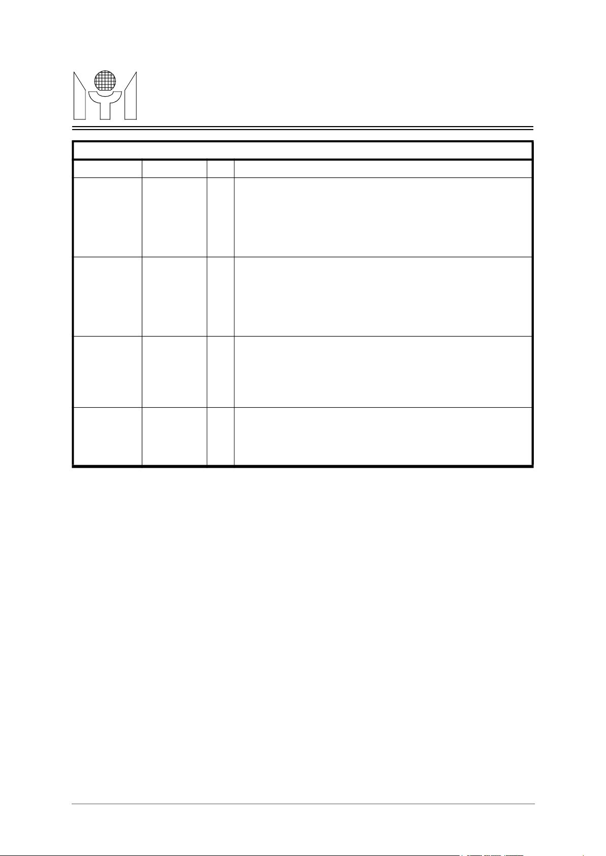
MTD658E Revision 1.1 05/25/2000
TECHNOLOGY
Auto MII_setting bypass : ( power on external jumper configuration )
- external pull_low (default ) : normal mode ( auto MII_setting); after
power_on, MTD658E will auto setup PHY devices be forced in half_
duplex mode for repeater apllication.
- external pull_low (default ) : MII setting PHY_ID start address from
- external pull_high: MII setting PHY_ID start address from
1522 bytes packet accept enable : ( power on external jumper configura-
- external pull_low (default ) : normal mode ( <=1518 bytes packet
- external pull_high: <= 1522 bytes packet accept
- external pull_low (default ) : normal mode (inter_repeater bus use
Power On Configuration Set Up Table (for 5 port mode)
Name Pin Number I/O Descriptions
TXEN2
42
PART4
I/O
- external pull_high: auto MII_setting bypass.
I/O PHY_ID 5h0b starting enable :(power on external jumper configuration)
MTD658EMYSON
MDC
LEDDAT
99
126
124
5h07 to 5h0b.
5h0b to 5h0f.
I/O
tion )
accept)
I/O External arbiter enable : ( power on external jumper configuration )
internal arbiter)
- external pull_high: inter_repeater bus use external arbiter .
14/23
Page 15

MTD658E Revision 1.1 05/25/2000
MTD658EMYSON
5.0 FUNCTIONAL DESCRIPTIONS
10M/100M dual speed Hub application. Since MTD658E build_in memory on chip, there are no need
any extra memorys in the application board.The MTD658E functions are described as follows:
MTD658E will switch individual port to their appropriated Hub core functions (10M or 100M).
repeater main state machine will starts to repeat the input packet to all ports except the input port. If
larger than or equal to two ports have input packet simultaneously, this will be treated as a collision, and
sion number over or equal to CClimit (10M CClimit default is 32, 100M CClimit default is 64), this port
monitor input message), but will continue output repeated messages to this partition port.
jabber_partition event. In 10M/100M partition state machine, longer than 1024 bit time continueous col-
this port will be partitioned. In 10M, jabber_partition function is not implemented.
received a longer than 65536 +/- 6.25% bit times packet, this receive port‘s receive/transmit path will be
5.4 MII Setting
in half duplex environment. The MTD658E will setting all PHY’s SMI register 4’s half/full duplex bit dur-
ing power on, and than restart auto-negotiation procedure to work in half duplex mode. In 8 port mode,
the PHY’s device ID should be setted from 5h04 - 5h0b (port0-7) or from 5h08 -5h0f (port0-7); In 5 port
domain, up to 4 MTD658Es can be stacked through this Inter-Bus without any external arbitration logic.
The Inter-Bus Interface includes IMASTER, IDATA (100M: use IDAT<3:0>, 10M: use only IDAT),
Inter-Bus, and only one MTD658E’s IMASTER can be tie high in a stackable Hub. IDATA are synchro-
TECHNOLOGY
The MTD658E is conformed to IEEE802.3 chapter 9 and IEEE802.3u clause 27 specifications. The
MTD658E provides 8 Reduced MII interfaces and an embedded two port switch (build_in 64k8 ASRAM
on chip) to construct a 10M/100M dual speed Hub application. And also, MTD658E can be configured
to 5 port mode, it will provide 4 RMII and 1 MII interface. Two Inter-Bus are also provided for stackable
5.1 Repeatation and data handling
8 independent RMII ports integrated with IEEE802.3 chapter 9 and IEEE802.3u clause 27 repeater
functions simultaneously. MTD658E embedded two Hub cores (10M and 100M) ,and each dedicated
RMII interface port can get per port’s speed information from per port speed input pin, and then
The MTD658E receive packets from each RMII ports, and redirect port’s input packet to 10M or 100M
Hub core according each port’s speed. The internal IEEE802.3 chapter 9 or IEEE802.3u clause 27
MTD658E will assert an arbitrary JAM pattern to all ports’ output until collision event disappear and network is idle.
5.2 Partition
The MTD658E provides 10M/100M auto partition/reconnection functions to guarantee the network segment performance by means of dectecting a consecutive collisions. Each dedicated RMII port has
implement a individual 10M/100M auto partition/reconnection state machine. If port’s consecutive colli-
will be partitioned. Reconnection will occurs after a larger than 512 bit time packet was received or
transmitted from this partitioned port without any collision.
When port is under partition state, MTD658E will not accept any input messages from this port (just
Some new partition criterions are also implement, such as long_collision_partition event,
lision will force port enter partition state. In 100M partition state machine, if port enter jabber_on state,
5.3 Jabber
The jabber protect function is used to prevent an illegally long packet reception. After the MTD658E
inhibited until carrier is no longer detected.
Due to HUB is an half duplex device, the MTD658E need to force all connected phsical devices to work
mode, the PHY device ID should be setted from 5h07 - 5h0b (port0-4) or from 5h0b -5h0f (port0-4).
5.5 Inter-Bus Interface
Two Inter-Bus Interface are provided by the MTD658E, One is 10M Inter-Bus Interface, the other is
100M Inter-Bus Interface. The Inter-Bus interface is designed for stackable hub application. For each
REQOUT, REQIN0-2, ICLK, IACKB, ICOLB pins. IMASTER decide which MTD658E can arbitrate the
15/23
Page 16

MTD658E Revision 1.1 05/25/2000
MTD658EMYSON
nous with ICLK. The MTD658E output REQOUT to inform Inter-Bus Interface that it need the Inter-Bus
asserted REQOUT will get the bus right and put the transmit data into IDATA. If the MTD658E did not
The Inter-Bus interface can also be programmed to EXT_ARB mode, using LEDDAT pin’s jumper set-
ting. In this mode, Inter-Bus interface need an external arbitration logic to arbitrate Inter-Bus operation.
And in this mode, the stackable capability is not limitted by the MTD658E’s REQIN pins number.
5.6 10M/100M packet Switch
5.7 Uplink Switch Port
The MTD658E can config one switch port as an uplink switch port. When UPSWEN pin is high, and
5.8 Memory Interface
embedded memory for packet buffering.
5.9 MII management
The MTD658E can be managed through MDC, MDIO pins. The MTD658E implements
for function control and status report (see Section 4.0 on page ).
tion. The LED data pin LEDDAT is high actived.
can shift the latched data into byte aligned shift register to drive LEDs.
The MTD658E also provide status pins to direct output per port’s receive activity/partition, 100M Hub
collision, 10M Hub collision, embedded ASRM memory test fail status.
The MTD658E implements
TABLE 1. MII registers
TECHNOLOGY
right. When IACKB is asserted by Inter-Bus master after REQOUT asserted, the MTD658E which
assert REQOUT , but IACKB is asserted, means this MTD658E can get data from IDATA bus. When
only one MTD658E output REQOUT to Inter-Bus Interface, IACKB will be asserted by Inter-Bus master
device, If larger than two MTD658E’s REQOUT were asserted, Inter-Bus master will not assert IACKB ,
but will assert ICOLB to inform all the connected MTD658Es.
The MTD658E inplements a 10/100M two port switch for 10M/100M packet switching. Total 2K address
entrys are provided for packets’ SA learning and DA routing; and alsoprovide automatic aging function
( aging time = 300secs). The input packet from 10MHub ( or 100M Hub) will be stored to external
memory first, while packet is good for forward ( CRC chech ok, length = 64Bytes ~ 1518Bytes or 1522
Bytes, and not local packets ) , than forward this packet to 100M Hub (or 10M Hub).
IMASTER pin is low, one of the intenal switch port is connect to 100M Hub, the other is connected to
RMII the highest port . In uplink switch mode, the highest port can operate in 10M/100M (in 8 port mode
: from SPD7 pin; in 5 port mode: from SPD4 pin ), and operate in half/full duplex (in 8 port mode: from
FD7 pin; in 5 port mode: from FD4 pin).
The MTD658E build-in an asynchronous SRAM as two port switchs’ packet buffers, total has 64K byte
3 MII registers
The management frame format is compliant to IEEE802.3u clause 22, and the device ID is fixed to
5’h1f internally.
5.10 LED display
The MTD658E implements three display modes, port RX activity, 10/100M domain collision, port parti-
One strobe pin LEDCLK(24 burst clock/per 42ms) is used to latch serial LEDDAT information, and user
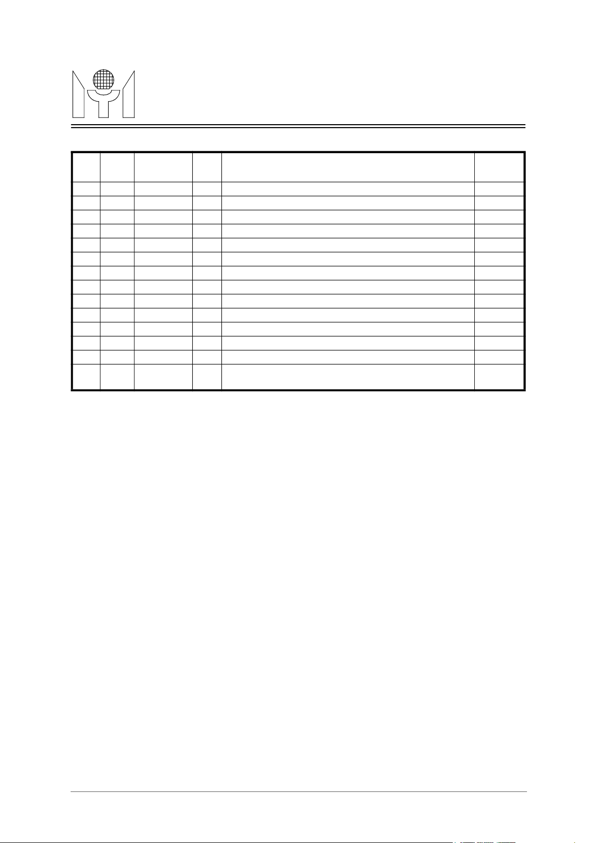
6.0 Registers
3 MII registers, define as following tables:
REG
Bits Name R/W Descriptions Default
NO
0 CtlReg0 R/W CONTROL REGISTER 0
0 Reserved. 1b0
1 DisPar10 Set this bit will disable 10M hub core partition function. 1b0
16/23
Page 17
MTD658E Revision 1.1 05/25/2000
TECHNOLOGY
"R/W" means read/writable.
Set high will program 100M partition cclimit to 128.
Set high will program 10M partition cclimit to 64.
AGE REGISTER
TABLE 1. MII registers
MTD658EMYSON
REG
Bits Name R/W Descriptions Default
NO
2 DisPar100 Set this bit will disable 100M hub core partition function. 1b0
3 DisJab10 Set this bit will disable 10M hub core Jabber function. 1b0
4 DisJab100 Set this bit will disable 100M hub core Jabber function. 1b0
5-8 Reserved 4b000
9 CClimit100
10 CClimit10
11-15 Reserved 2b00
1 CtlReg1 R/W CONTROL REGISTER 1 16h0000
0-7 DisPort Set bits high disable port 0-7 RMII ports. 8h000
8-15 Reserved.
2 Reserved
3 Reserved
4 AgeReg R/W
0-15 AgeTime
Change this register’s content will change Aging Time
value(Unit:Sec)
1b0(64)
1b0(32)
16h12c
17/23
Page 18
MTD658E Revision 1.1 05/25/2000
MTD658EMYSON
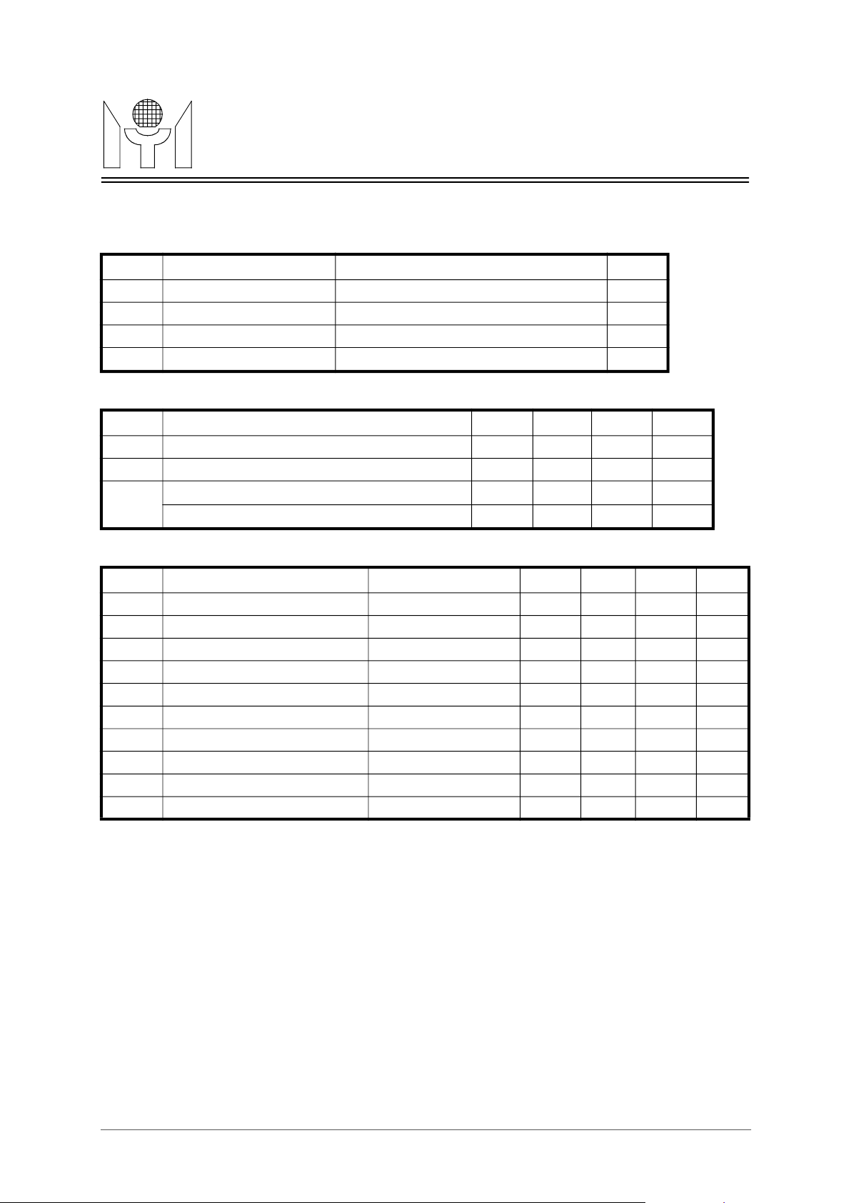
7.1 Absolute Maximum Ratings
Power Supply Voltage
Storage Temperature
Commercial Power Supply Voltage
Industrial Junction Operating Temperature
Tri-state Leakage Current
Bi-direction buffer Capacitance
Input High Voltage
Output High Voltage
Output Low Voltage
TECHNOLOGY
7.0 Electrical Characteristics
Symbol Parameter RATING Unit
V
CC
V
V
T
Input Voltage -0.3 to Vcc+0.3 V
IN
Output Voltage -0.3 to Vcc+0.3 V
OUT
STG
7.2 Recommended Operating Conditions
Symbol Parameter Min. Typ. Max. Unit
V
CC
V
T
Input Voltage 0 - Vcc V
IN
Commercial Junction Operating Temperature 0 25 115
OPR
-0.3 to 3.6 V
-55 to 150
o
3.0 3.3 3.6 V
-40 25 125
C
o
o
C
C
7.3 DC Electrical Characteristics
Symbol Parameter Conditions Min. Typ. Max. Unit
I
Input Leakage Current no pull-up or down -1 1 uA
IL
I
OZ
C
C
C
V
V
V
V
Input Capacitance 2.8 pF
IN
Output Capacitance 2.7 4.9 pF
OUT
BID3
Input Low Voltage CMOS 0.3*Vcc V
IL
IH
OH
OL
R
Input Pull-up/down resistance
I
IOL=2,4,8,12,16,24mA
IOH=2,4,8,12,16,24mA
CMOS 0.7*Vcc V
VIL=0V or VIH=V
CC
(Under recommended operating conditions and Vcc = 3.0 ~ 3.6V, Tj = 0 to +115 oC)
-10 10 uA
2.7 4.9 pF
2.4 V
0.4 V
75 KOhm
18/23
Page 19
MTD658E Revision 1.1 05/25/2000
TECHNOLOGY
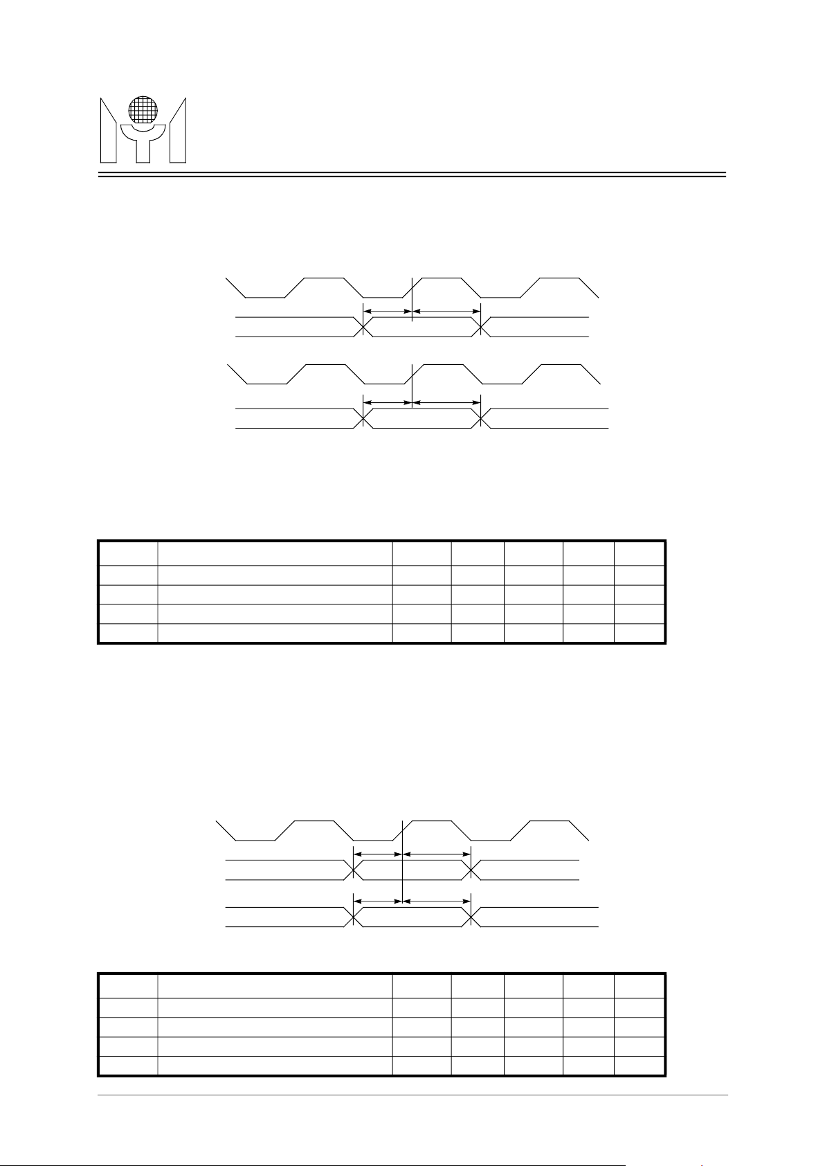
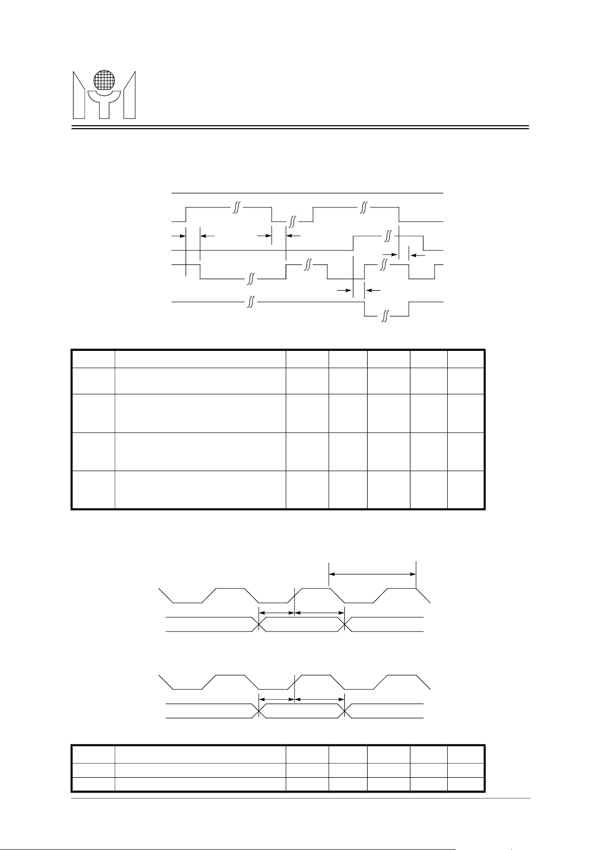
FIGURE 1. MII timing
FIGURE 2. RMII timing
7.4 Electrical Characteristics
MTD658EMYSON
RXCLK0
CRS0/RXDV0
RXD0[3:0]
TXCLK0
TXEN0
TXD0[3:0]
Symbol Parameter Min. Typ. Max. Unit Note
T5 MII input setup time 10 nS
T6 MII input hold time 10 nS
T7 MII output setup time 3 nS
T8 MII output hold time 5 nS
T5
T7
T6
Valid
T8
Valid
REFCLK
CRSDV
RXD[1:0]
TXEN
TXD[1:0]
Symbol Parameter Min. Typ. Max. Unit Note
T1 RMII input setup time 1 nS
T2 RMII input hold time 1 nS
T3 RMII output setup time 3 nS
T4 RMII output hold time 5 nS
T1
T3
T2
Valid
T4
Valid
19/23
Page 20
MTD658E Revision 1.1 05/25/2000
TECHNOLOGY
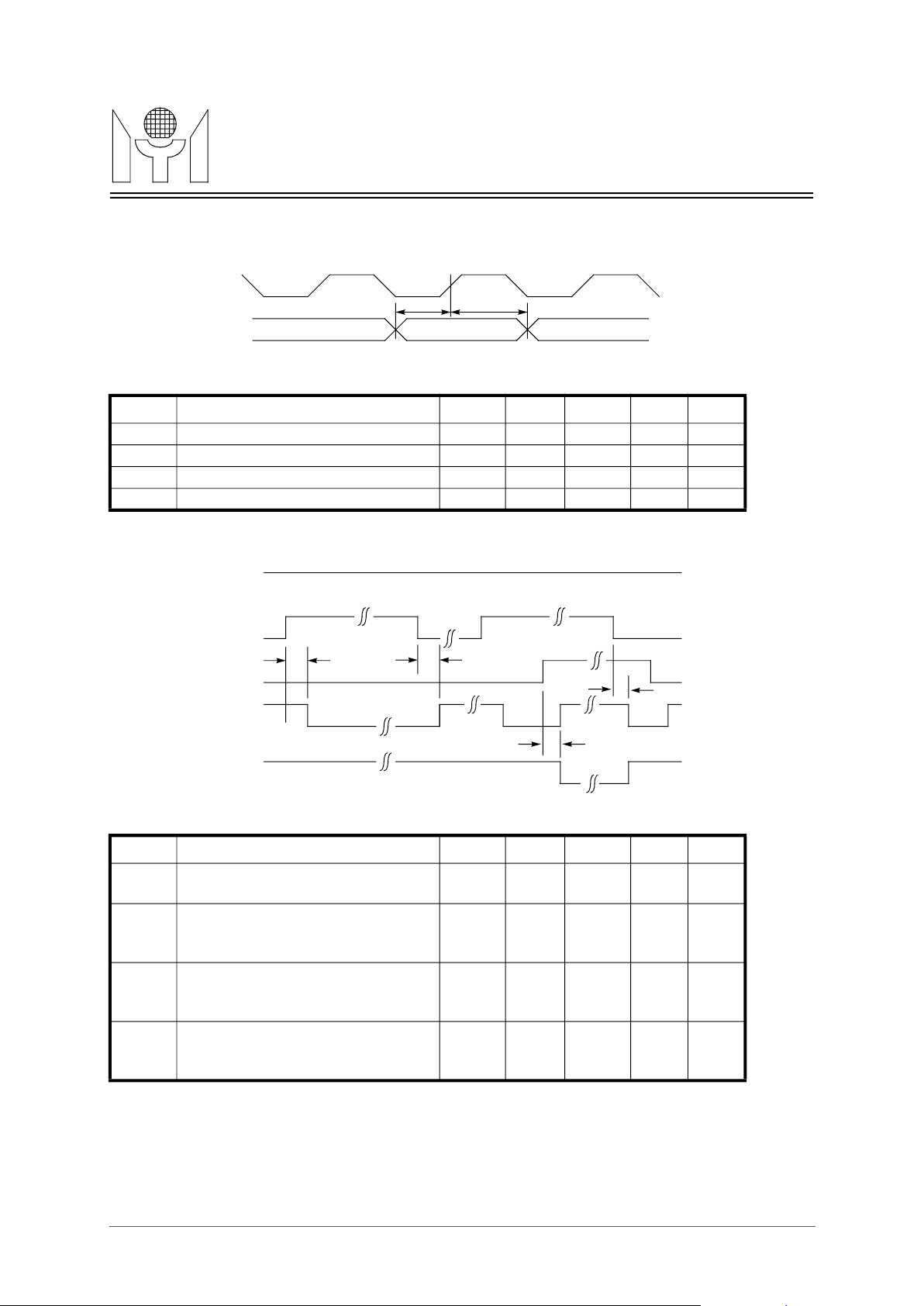
Note 1 : In 10M/100M Inter-Bus interface, T15-T18 have the same value.
Inter-Bus output setup time(100M)
Inter-Bus output setup time(10M)
Inter-Bus output hold time(100M)
Inter-Bus output hold time(10M)
Inter-Bus master REQOUT asserted
to IACKB asserted propogation delay
Inter-Bus master REQOUT deas-
Inter-Bus master REQIN asserted to
propogation delay(SOJ)
Inter-Bus master REQOUT deas-
asserted) propogation delay(EOJ)
FIGURE 3. Inter-Bus Interface timing I
FIGURE 4. Inter-Bus Interface timing II
MTD658EMYSON
ICLK100,
ICLK10
IDATA100,
IDAT10
Symbol Parameter Min. Typ. Max. Unit Note
T13
T14
IMASTER
REQOUT100,
REQOUT10
REQIN100,
REQIN10
IACKB100,
IACKB10
ICOLB100,
ICOLB10
T15
T13
T14
Valid
15 20 nS
50 nS
20 25 nS
50 nS
T16
T18
T17
Symbol Parameter Min. Typ. Max. Unit Note
T15
T16
T17
T18
serted to IACKB deasserted propogation delay
IACKB deasserted(ICOLB asserted)
serted to IACKB asserted(ICOLBde-
7 20 nS 1
0 1 5 nS 1
5 17 nS 1
0 1 5 nS 1
20/23
Page 21
MTD658E Revision 1.1 05/25/2000
MTD658EMYSON
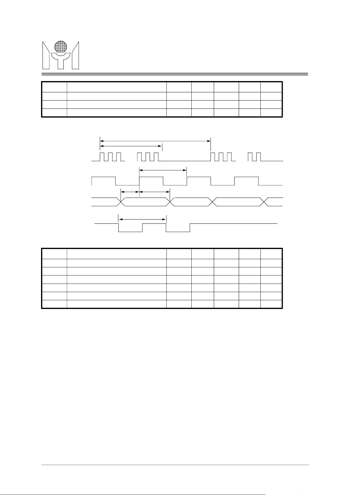
Note 2 : In 10M/100M Inter-Bus interface, T19-T22 have the same value.
Inter-Bus slave REQOUT asserted to
Inter-Bus slave REQOUT deasserted
propogation delay(SOJ)
Inter-Bus slave REQOUT deasserted
serted) propogation delay(EOJ)
MDC clock cycle
FIGURE 5. Inter-Bus Interface timing III
FIGURE 6. MII Management timing
TECHNOLOGY
IMASTER
REQOUT100,
REQOUT10
REQIN100,
REQIN10
IACKB100,
IACKB10
ICOLB100,
ICOLB10
Symbol Parameter Min. Typ. Max. Unit Note
T19
T20
T22
T21
T19
T20
T21
T22
IACKB asserted propogation delay
to IACKB deasserted propogation
delay
Inter-Bus slave REQIN asserted to
IACKB deasserted(ICOLB asserted)
to IACKB asserted(ICOLBdeas-
Input Timing
MDC
MDIO
Output Timing
5 20 nS 2
5 20 nS 2
5 20 nS 2
5 20 nS 2
T23
T24
T25
Valid
MDC
MDIO
Symbol Parameter Min. Typ. Max. Unit Note
T23
T23 MDIO input setup time 10 nS
T26
T27
Valid
21/23
400 nS
Page 22
MTD658E Revision 1.1 05/25/2000
MTD658EMYSON
LED burst clock cycle time
LEDDAT to LEDCLK setup time
LEDDAT to LEDCLK setup time
FIGURE 7. LED output timing
TECHNOLOGY
Symbol Parameter Min. Typ. Max. Unit Note
T25 MDIO input hold time 10 nS
T26 MDIO output setup time 182 194 nS
T27 MDIO output hold time 206 218 nS
T29
T28
LEDCLK
LEDCLK
T31
LEDDAT
RXACT7-0,
XCOL100,
XCOL10
.... ....
T30
T32
T33
Symbol Parameter Min. Typ. Max. Unit Note
T28 24 LED burst clocks duration 3.84 uS
T29
T30 LED burst clock cycle 160 nS
T31
T32
T33 LED Output flash rate 42 mS
42 mS
80 nS
80 nS
22/23
Page 23
MTD658E Revision 1.1 05/25/2000
TECHNOLOGY
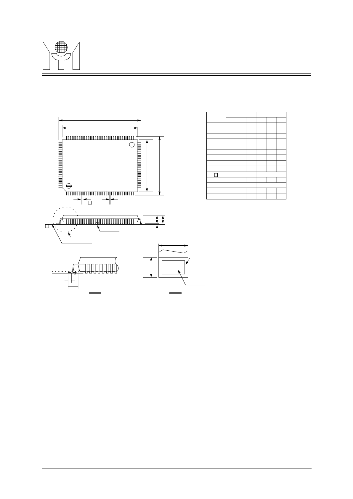
1.Dimension D1 & E1 do not include mold protrusion.
3.Controlling dimension : Millimeter.
8.0 128 pin PQFP Package Data
D
1
D
65102
103
128
1 38
y
Seating Plane
See Detail A
e
B
See Detail B
64
39
MTD658EMYSON
Dimension in inch Dimension in mm
Symbol
Min Norm Max Min Norm Max
A - - 0.134 - - 3.40
A1 0.010 - - 0.25 - -
A2 0.107 0.112 0.117 2.73 2.85 2.97
B 0.007 0.009 0.011 0.17 0.22 0.27
C 0.004 - 0.008 0.09 - 0.20
D 0.906 0.913 0.921 23.00 23.20 23.40
D
0.783 0.787 0.791 19.90 20.00 20.10
1
1
E
E
A
A1 A2
B
E 0.669 0.677 0.685 17.00 17.20 17.40
E
0.547 0.551 0.555 13.90 14.00 14.10
1
e 0.020 BSC 0.50 BSC
L 0.029 0.035 0.041 0.73 0.88 1.03
L1 0.063 BSC 1.60 BSC
y - - 0.004 - - 0.10
o
z
Note:
But mold mismatch is included. Allowable protrusion is .25mm /.010” per side.
2.Dimension B does not include dambar protrusion. Allowable dambar protrusion .08mm/.003”. Total in excess of the B dimemsion at max imum material
condition. Dambar cannot be located on the lower radius or the foot.
-
0
7o0
o
o
-
7
Gage Plane
L
With Plating
C
z
Base Metal
L1
Detail A
Detail B
23/23
 Loading...