

Page 1
MT9300
Multi-Channel Voice Echo Canceller
Advance Information
Features
• Independent multiple channels echo
cancellation; from 32 channels of 64ms to 16
channels of 128ms with the ability to mix
channels at 128ms or 64ms in any combination
• Independent Power Down mode for each group
of 2 channels for power management
• Conforms to ITU-T G.165 and G.168
Recommendations
• Field proven, high quality performance
• Compatible to ST-BUS and GCI interface at
2Mb/s serial PCM
• PCM coding, µ/A-Law ITU-T G.711 or sign
magnitude
• Per channel Fax/Modem G.164 2100Hz or
G.165 2100Hz phase reversal Tone Disable
• Per channel echo canceller parameters control
• Transparent data transfer and mute
• Non-Linear processor with high quality
subjective performance
• Protection against narrow band signal
divergence
• Offset nulling of all PCM channels
• 10 MHz or 20 MHz master clock operation
• 3.3 Volts operation with 5-Volt tolerant inputs
• No external memory required
• Non-multiplexed microprocessor interface
• IEEE-1149.1 (JTAG) Test Access Port
DS5030 ISSUE 2 May 1999
Ordering Information
MT9300AL 160-Pin MQFP
-40°C to +85°C
Applications
• Voice over IP network gateways
• Voice over ATM, Frame Relay
• T1/E1/J1 multichannel echo cancellation
• Wireless base stations
• Echo Canceller pools
• DCME, satellite and multiplexer systems
Description
The MT9300 Voice Echo Canceller implements a
cost effective solution for telephony voice-band echo
cancellation conforming to ITU-T G.168
requirements. The MT9300 architecture contains 16
groups of two echo cancellers (ECA and ECB) which
can be configured to provide two channels of 64
milliseconds or one channel of 128 milliseconds
echo cancellation. This provides 32 channels of 64
milliseconds to 16 channels of 128 milliseconds echo
cancellation or any combination of the two
configurations. The MT9300 supports ITU-T G.165
and G.164 tone disable requirements.
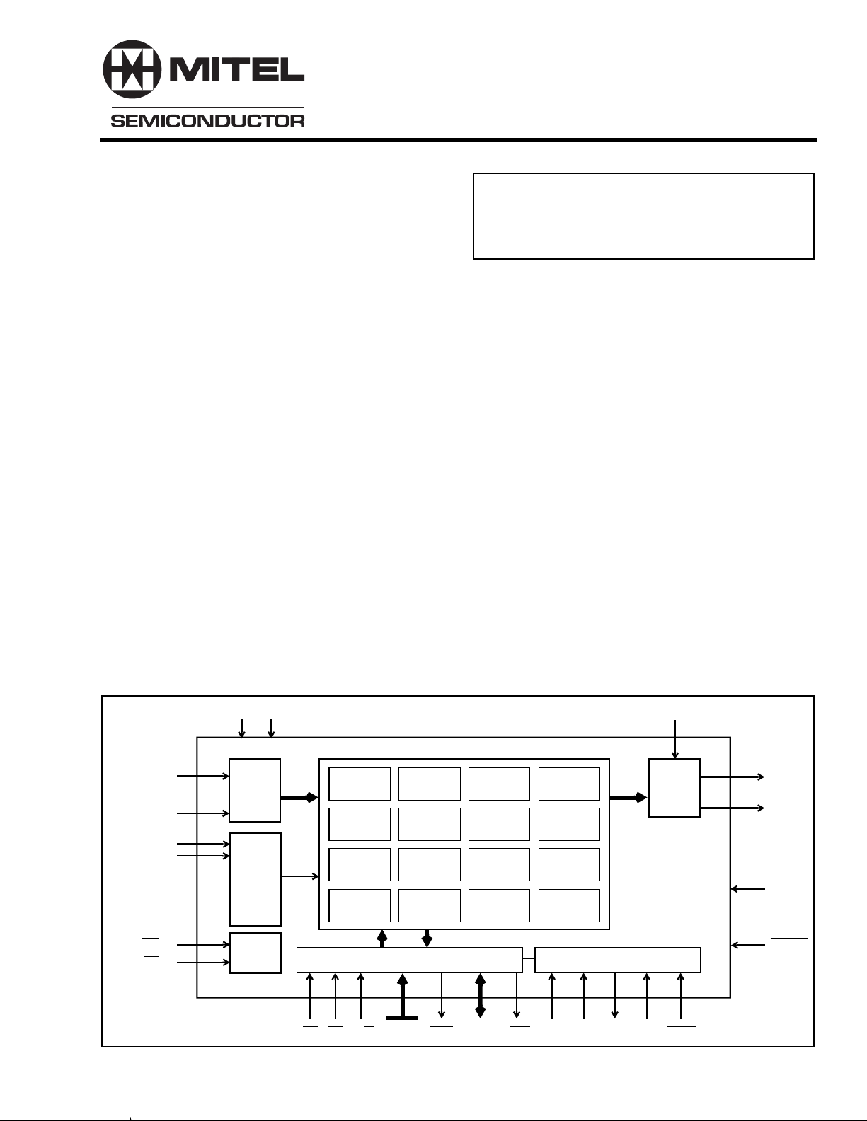
Rin
Sin
MCLK
Fsel
C4i
F0i
V
DD
Serial
to
Parallel
PLL
Timing
Unit
V
SS
Echo Canceller Pool
Group 0
ECA/ECB
Group 4
ECA/ECB
Group 8
ECA/ECB
Group 12
ECA/ECB
DS CS R/W A10-A0 DTA D7-D0
Group 1
ECA/ECB
Group 5
ECA/ECB
Group 9
ECA/ECB
Group 13
ECA/ECB
Group 2
ECA/ECB
Group 6
ECA/ECB
Group 10
ECA/ECB
Group 14
ECA/ECB
IRQ
Group 3
ECA/ECB
Group 7
ECA/ECB
Group 11
ECA/ECB
Group 15
ECA/ECB
TDI TDO TCK TRSTTMS
Note:
Refer to Figure 3
for Echo Canceller
block diagram
Test PortMicroprocessor Interface
ODE
Parallel
to
Serial
Rout
Sout
IC0
RESET
Figure 1 - Functional Block Diagram
1
Page 2
MT9300 Advance Information
ODE
Rout
IC0
V
SSVSS
IC0
IC0
IC0
IC0
DD
Sout
V
C4i
F0i
Rin
Sin
V
SS
NC
DD
V
NCNCNC
NC
V
SS
NCNCNC
V
NC
NCNCNCNCNC
DD
V
NCNCNCNCNC
SS
V
SS
IC0
IC0
NC
V
NC
NC
NC
NC
NC
NC
NC
NC
IC0
IC0
IC0
NC
NC
V
V
MCLK
V
V
Fsel
IC0
IC0
PLLVSS
PLLVDD
V
V
NC
NC
TMS
TDI
TDO
TCK
TRST
IC0
RESET
V
NC
DD
SS
SS
DD
DD
SS
SS
DD
121
123
125
127
129
131
133
135
137
139
141
143
145
147
149
151
153
155
157
159
103105107109
101 97115 113
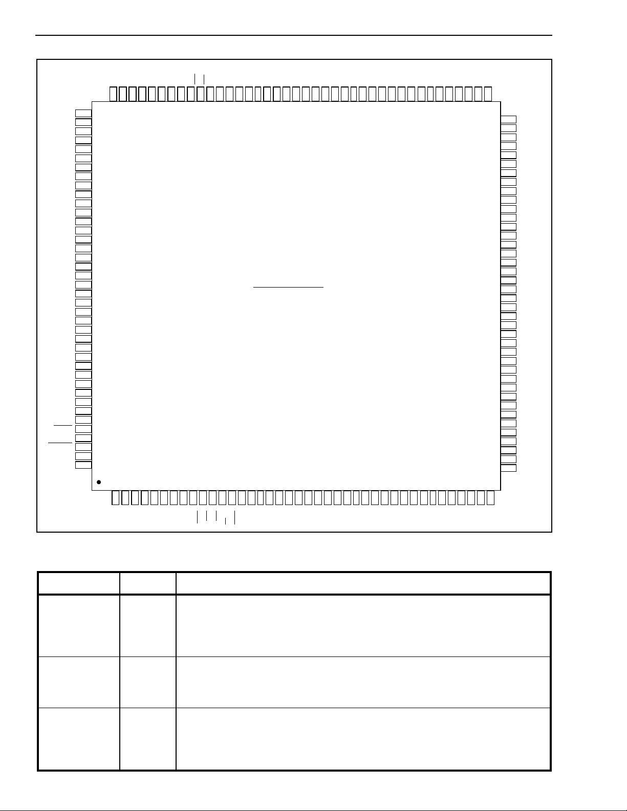
160 Pin MQFP
171197252321193 295273113 151
936791
99
95111117119
33
858789
83 81
393735
79
77
75
73
71
69
65
63
61
59
57
55
53
51
49
47
45
43
41
NC
V
NC
V
V
NC
NC
NC
NC
NC
NC
NC
NC
NC
NC
NC
NC
V
NC
NC
NC
IC0
V
IC0
A10
A9
A8
V
A7
A6
A5
A4
V
A3
A2
A1
A0
V
NC
NC
DD
SS
SS
DD
SS
DD
SS
DD
SS
W
R/
NC
DTA
CS
DS
IRQ
VDDNC
NCNCNC
NC
VSSV
NC
D0
VSSNC
D1
D2
VDDD3
Figure 2 - Pin Connections
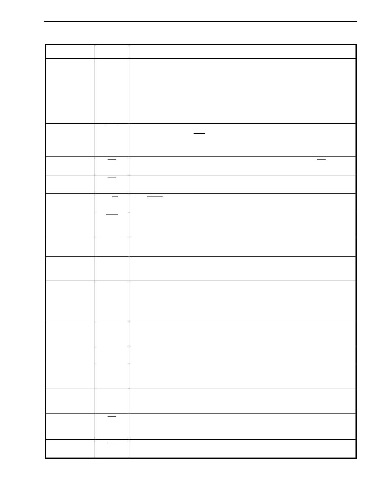
Pin Description
Pin # Name Description
1, 2, 17, 27, 37,
38, 48, 58, 76, 77,
81, 87, 98, 108,
118, 119, 138,
139, 148, 149
8, 22, 32, 43, 53,
63, 79, 93, 103,
113, 124, 141,
142, 159
57, 59, 114, 115,
116,117, 120,
121,122, 133,
134, 135, 144,
145, 157,
2
V
SS
V
DD
Ground.
Positive Power Supply. Nominally 3.3 volt.
IC0 Internal Connection. These pins must be connected to VSS for normal operation.
D4
D5
D6
NC
NC
NC
VSSD7
NC
NC
NC
VDDNC
NC
NC
VSSVSSNC
Page 3
Advance Information MT9300
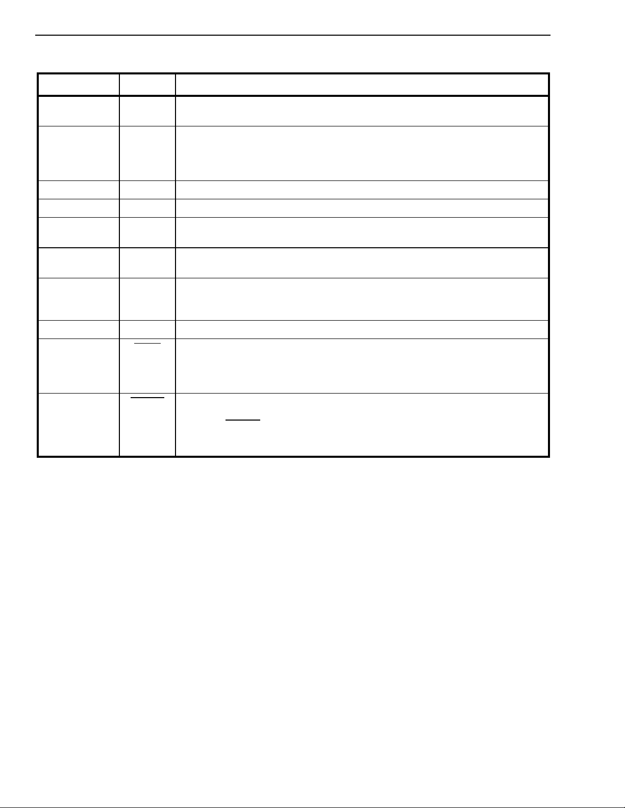
Pin Description (continued)
Pin # Name Description
3 to 7, 14 to 16,
28 to 31, 33 to 36,
39 to 42, 60 to 62,
64 to 75, 78, 80,
82 to 86, 88 to 92,
94 to 97, 99 to102,
104, 123,
125 to 132, 136,
137, 150,151,160
9 IRQ Interrupt Request (Open Drain Output). This output goes low when an interrupt
10 DS Data Strobe (Input). This active low input works in conjunction with CS to enable
11 CS Chip Select (Input). This active low input is used by a microprocessor to activate
12 R/W Read/Write (Input). This input controls the direction of the data bus lines (D7-D0)
13 DTA Data Transfer Acknowledgment (Open Drain Output). This active low output
NC No connection. These pins must be left open for normal operation.
occurs in any channel. IRQ returns high when all the interrupts have been read
from the Interrupt FIFO Register. A pull-up resistor (1K typical) is required at this
output.
the read and write operations.
the microprocessor port.
during a microprocessor access.
indicates that a data bus transfer is completed. A pull-up resistor (1K typical) is
required at this output.
18, 19, 20, 21,
23, 24, 25, 26
44, 45,46, 47,49,
50, 51,52,54, 55,
56
D0 - D3,
D4 - D7
Data Bus D0 - D7 (Bidirectional). These pins form the 8-bit bidirectional data bus
of the microprocessor port.
A0 - A10 Address A0 to A10 (Input). These inputs provide the A10 - A0 address lines to
the internal registers.
105 ODE Output Drive Enable (Input). This input pin is logically AND’d with the ODE bit-6
of the Main Control Register. When both ODE bit and ODE input pin are high, the
Rout and Sout ST-BUS outputs are enabled.
When the ODE bit is low or the ODE input pin is low, the Rout and Sout ST-BUS
outputs are high impedance.
106 Sout Send PCM Signal Output (Output). Port 1 TDM data output streams.
Sout pin outputs serial TDM data streams at 2.048 Mb/s with 32 channels per
stream.
107 Rout Receive PCM Signal Output (Output). Port 2 TDM data output streams. Rout pin
outputs serial TDM data streams at 2.048 Mb/s with 32 channels per stream.
109 Sin Send PCM Signal Input (Input). Port 2 TDM data input streams.
Sin pin receives serial TDM data streams at 2.048 Mb/s with 32 channels per
stream.
110 Rin Receive PCM Signal Input (Input). Port 1 TDM data input streams.
Rin pin receives serial TDM data streams at 2.048 Mb/s with 32 channels per
stream.
111 F0i Frame Pulse (Input). This input accepts and automatically identifies frame
synchronization signals formatted according to ST-BUS or GCI interface
specifications.
112 C4i Serial Clock (Input). 4.096 MHz serial clock for shifting data in/out on the serial
streams (Rin, Sin, Rout, Sout).
3
Page 4
MT9300 Advance Information
Pin Description (continued)
Pin # Name Description
140 MCLK Master Clock (Input). Nominal 10MHz or 20MHz Master Clock input. May be
connected to an asynchronous (relative to frame signal) clock source.
143 Fsel Frequency select (Input). This input selects the Master Clock frequency
operation. When Fsel pin is low, nominal 19.2MHz Master Clock input must be
applied. When Fsel pin is high, nominal 9.6MHz Master Clock input must be
applied.
146 PLLV
147 PLLV
152 TMS Test Mode Select (3.3V Input). JTAG signal that controls the state transitions of
153 TDI T est Serial Data In (3.3V Input).JTAG serial test instructions and data are shifted
154 TDO Test Serial Data Out (Output). JTAG serial data is output on this pin on the falling
155 TCK Test Clock (3.3V Input). Provides the clock to the JTAG test logic.
156 TRST Test Reset (3.3V Input). Asynchronously initializes the JTAG TAP controller by
158 RESET Device Reset (Schmitt Trigger Input). An active low resets the device and puts
PLL Ground. Must be connected to V
SS
PLL Power Supply. Must be connected to V
DD
the TAP controller. This pin is pulled high by an internal pull-up when not driven.
in on this pin. This pin is pulled high by an internal pull-up when not driven.
edge of TCK. This pin is held in high impedance state when JTAG scan is not
enabled.
putting it in the Test-Logic-Reset state. This pin should be pulsed low on power-up
or held low , to ensure that the MT9300 is in the normal functional mode. This pin is
pulled by an internal pull-down when not driven.
the MT9300 into a low-power stand-by mode.
When the RESET pin is returned to logic high and a clock is applied to the
MCLK pin, the device will automatically execute initialization routines, which
preset all the Control and Status Registers to their default power-up values.
Device Overview
The MT9300 architecture contains 32 echo
cancellers divided into 16 groups. Each group has
two echo cancellers, Echo Canceller A and Echo
Canceller B. Each group can be configured in
Normal, Extended Delay or Back-to-Back
configurations. In Normal configuration, a group of
echo cancellers provides two channels of 64ms echo
cancellation, which run independently on different
channels. In Extended Delay configuration, a group
of echo cancellers achieves 128ms of echo
cancellation by cascading the two echo cancellers (A
& B). In Back-to-Back configuration, the two echo
cancellers from the same group are positioned to
cancel echo coming from both directions in a single
channel, providing full-duplex 64ms echo
cancellation.
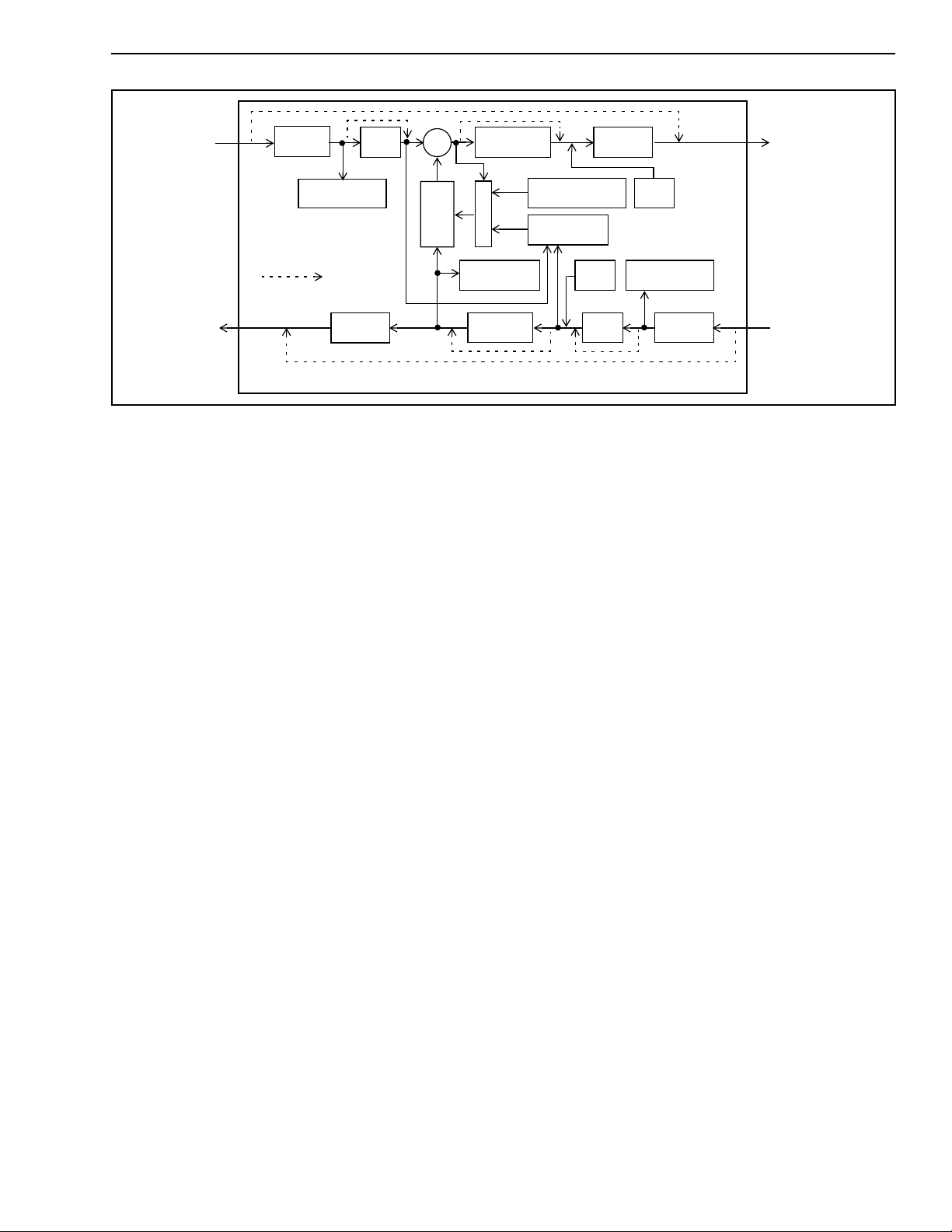
Each echo canceller contains the following main
elements (see Figure 3).
SS
DD
• Adaptive Filter for estimating the echo channel
• Subtractor for cancelling the echo
• Double-Talk detector for disabling the filter
adaptation during periods of double-talk
• Non-Linear Processor for suppression of
residual echo
• Disable Tone Detectors for detecting valid
disable tones at the input of receive and send
paths
• Narrow-Band Detector for preventing Adaptive
Filter divergence caused by narrow-band
signals
• Offset Null filters for removing the DC
component in PCM channels
• 12dB attenuator for signal attenuation
• Parallel controller interface compatible with
Motorola microcontrollers
• PCM encoder/decoder compatible with µ/ALaw ITU-T G.711 or Sign-Magnitude coding
4
Page 5
Advance Information MT9300
Sin
(channel N)
ST-BUS
PORT2
Rout
(channel N)
µ/A-Law/
Linear
Disable Tone
Programmable
Bypass
Detector
Offset
Null
Linear/
µ/A-Law
Echo Canceller (N), where 0 ≤ N ≤ 31
+
-
Adaptive
Filter
Narrow-Band
Attenuator
Figure 3 - Echo Canceller Functional Block Diagram
Each echo canceller in the MT9300 has four
functional states:
and
Enable Adaptation
Mute,Bypass,Disable Adaptation
. These are explained in the
section entitled Echo Canceller Functional States.
Adaptive Filter
For each group of echo cancellers, the Adaptive
Filter is a 1024 tap FIR adaptive filter which is
divided into two sections. Each section contains 512
taps providing 64ms of echo estimation. In Normal
configuration, the first section is dedicated to
channel A and the second section to channel B. In
Extended Delay configuration, both sections are
cascaded to provide 128ms of echo estimation in
channel A. In Back-to Back configuration, the first
section is used in the receive direction and the
second section is used in the transmit direction for
the same channel.
Double-Talk Detector
Double-Talk is defined as those periods of time when
signal energy is present in both directions
simultaneously. When this happens, it is necessary
to disable the filter adaptation to prevent divergence
of the Adaptive Filter coefficients. Note that when
double-talk is detected, the adaptation process is
halted but the echo canceller continues to cancel
echo using the previous converged echo profile.
Non-Linear
Processor
Control
Detector
12dB
Microprocessor
Interface
Double-Talk
Detector
µ/A-Law
MuteR
Offset
Null
Linear/
MuteS
Disable Tone
Detector
µ/A-Law/
Linear
Sout
(channel N)
ST-BUS
PORT1
Rin
(channel N)
where DTDT is the Double-Talk Detection Threshold.
Lsin and Lrin are signal levels expressed in dBm0.
A different method is used when it is uncertain
whether Sin consists of a low level double-talk signal
or an echo return. During these periods, the
adaptation process is slowed down but it is not
halted. The convergence speed is shown by the
CONV bit in the Status Register.
In G.168 standard, the echo return loss is expected
to be at least 6dB. This implies that the Double-Talk
Detector Threshold (DTDT) should be set to 0.5
(-6dB). However, in order to get additional
guardband, the DTDT is set internally to 0.5625
(-5dB).
In some applications the return loss can be higher or
lower than 6dB. The MT9300 allows the user to
change the detection threshold to suit each
application’s need. This threshold can be set by
writing the desired threshold value into the DTDT
register.
The DTDT register is 16 bits wide. The register value
in hexadecimal can be calculated with the following
equation:
DTDT
= hex(DTDT
(hex)
(dec)
* 32768)
A double-talk condition exists whenever the relative
signal levels of Rin (Lrin) and Sin (Lsin) meet the
following condition:
Lsin > Lrin + 20log10(DTDT)
where 0 < DTDT
(dec)
< 1
Example: For DTDT = 0.5625 (-5dB), the
hexadecimal value becomes
hex(
0.5625 * 32768) = 4800h
5
Page 6
MT9300 Advance Information
Non-Linear Processor (NLP)
After echo cancellation, there is always a small
amount of residual echo which may still be audible.
The MT9300 uses an NLP to remove residual echo
signals which have a level lower than the Adaptive
Suppression Threshold (TSUP in G.168). This
threshold depends upon the level of the Rin (Lrin)
reference signal as well as the programmed value of
the Non-Linear Processor Threshold register
(NLPTHR). TSUP can be calculated by the following
equation:
TSUP = Lrin + 20log10(NLPTHR)
where NLPTHR is the Non-Linear Processor
Threshold register value and Lrin is the relative
power level expressed in dBm0.
When the level of residual error signal falls below
TSUP, the NLP is activated further attenuating the
residual signal to less than -65dBm0. To prevent a
perceived decrease in background noise due to the
activation of the NLP, a spectrally-shaped comfort
noise, equivalent in power level to the background
noise, is injected. This keeps the perceived noise
level constant. Consequently, the user does not hear
the activation and de-activation of the NLP.
present for a minimum of one second with at least
one phase reversal, the Tone Detector will tr igger.
G.164 recommendation defines the disable tone as a
2100 Hz (±21Hz) sine wave with a power level
between 0 to -31dBm0. If the disable tone is present
for a minimum of 400 milliseconds, with or without
phase reversal, the Tone Detector will tr igger.
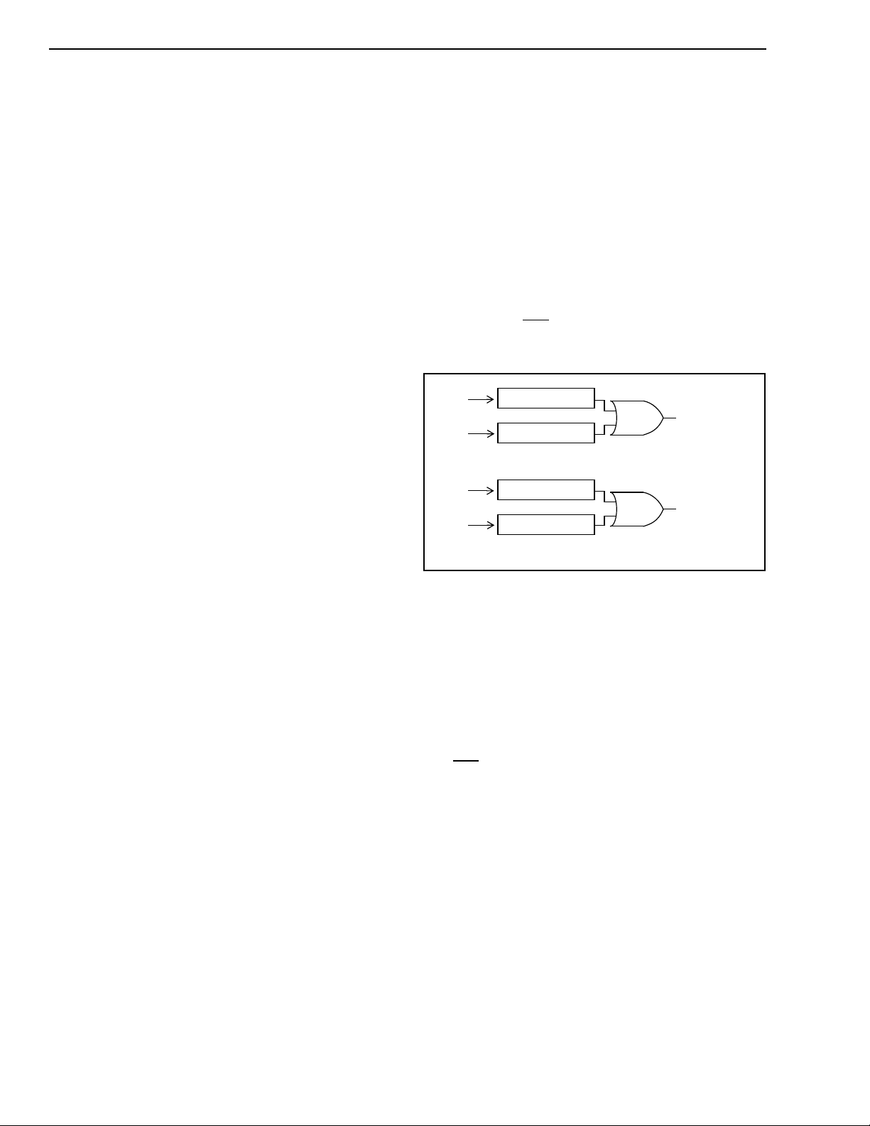
The MT9300 has two Tone Detectors per channels
(for a total of 64) in order to monitor the occurrence
of a valid disable tone on both Rin and Sin. Upon
detection of a disable tone, TD bit of the Status
Register will indicate logic high and an interrupt is
generated (i.e. IRQ pin low). Refer to Figure 4 and to
the Interrupts section.
Rin
Sin
Rin
Sin
Tone Detector
Tone Detector
Echo Canceller A
Tone Detector
Tone Detector
Echo Canceller B
ECA
Status reg
TD bit
ECB
Status reg
TD bit
The NLP processor can be disabled by setting the
NLPDis bit to “1” in Control Register 2.
The NLPTHR register is 16 bits wide. The register
value in hexadecimal can be calculated with the
following equation:
NLPTHR
where 0 < NLPTHR
= hex(NLPTHR
(hex)
< 1
(dec)
(dec)
* 32768)
The comfort noise injection can be disabled by
setting the INJDis bit to “1” in Control Register A1/
B1.
It should be noted that the NLPTHR is valid and the
comfort noise injection is active only when the NLP is
enabled.
Disable Tone Detector
G.165 recommendation defines the disable tone as
having the following characteristics: 2100 Hz
(±21Hz) sine wave, a power level between -6 to
-31dBm0, and a phase reversal of 180 degrees (±25
degrees) every 450ms (±25ms). If the disable tone is
Figure 4 - Disable Tone Detection
Once a Tone Detector has been triggered, there is
no longer a need for a valid disable tone (G.164 or
G.165) to maintain Tone Detector status (i.e. TD bit
high). The Tone Detector status will only release (i.e.
TD bit low) if the signals Rin and Sin fall below 30dBm0, in the frequency range of 390Hz to 700Hz,
and below -34dBm0, in the frequency range of
700Hz to 3400Hz, for at least 400ms. Whenever a
Tone Detector releases, an interrupt is generated
(i.e. IRQ pin low).
The selection between G.165 and G.164 tone
disable is controlled by the PHDis bit in Control
Register 2 on a per channel basis. When the PHDis
bit is set to 1, G.164 tone disable requirements are
selected.
In response to a valid disable tone, the echo
canceller must be switched from the Enable
Adaptation state to the Bypass state. This can be
done in two ways, automatically or externally. In
automatic mode, the Tone Detectors internally
control the switching between Enable Adaptation and
Bypass states. The automatic mode can be activated
by setting the AutoTD bit in Control Register 2 to
high. In external mode, an external controller is
needed to service the interrupts and poll the TD bits
6
Page 7
Advance Information MT9300
in the Status Registers. Following the detection of a
disable tone (TD bit high) on a given channel, the
external controller must switch the echo canceller
from Enable Adaptation to Bypass state.
Narrow Band Signal Detector (NBSD)
Single or dual frequency tones (i.e. DTMF tones)
present in the receive input (Rin) of the echo
canceller for a prolonged period of time may cause
the Adaptive Filter to diverge. The Narrow Band
Signal Detector (NBSD) is designed to prevent this
divergence by detecting single or dual tones of
arbitrary frequency, phase, and amplitude. When
narrow band signals are detected, the adaptation
process is halted but the echo canceller continues to
cancel echo.
The NBSD can be disabled by setting the NBDis bit
to “1” in Control Register 2.
Offset Null Filter
Adaptive filters in general do not operate properly
when a DC offset is present at any inputs. To remove
the DC component, the MT9300 incorporates Offset
Null filters in both Rin and Sin inputs.
The offset null filters can be disabled by setting the
HPFDis bit to “1” in Control Register 2.
Device Configuration
The MT9300 architecture contains 32 echo
cancellers divided into 16 groups. Each group has
two echo cancellers which can be individually
controlled (Echo Canceller A and B). They can be set
in three distinct configurations: Normal, Back-to-
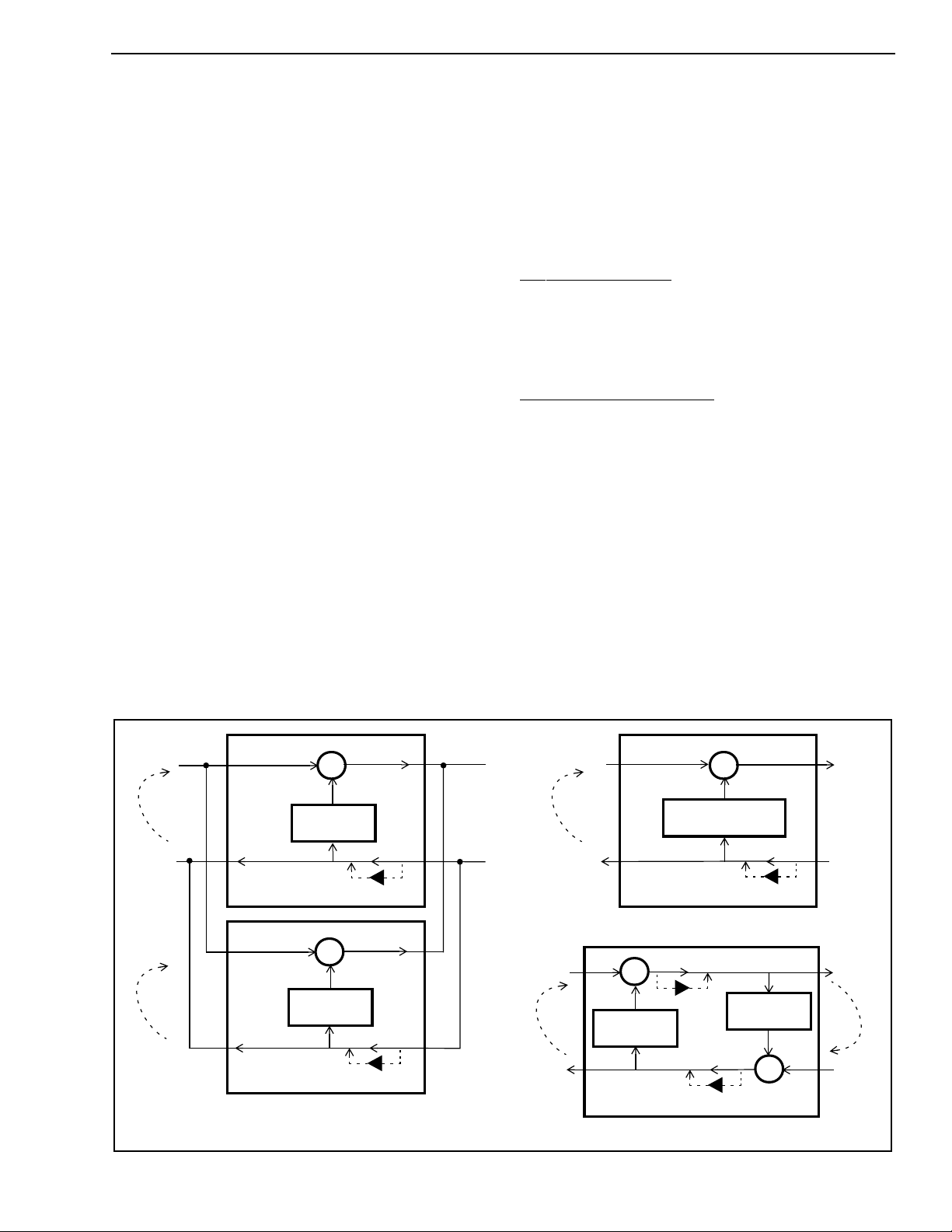
Back, and Extended Delay. See Figure 5.
Normal Configuration
In Normal configuration, the two echo cancellers
(Echo Canceller A and B) are positioned in parallel,
as shown in Figure 5a, providing 64 milliseconds of
echo cancellation in two channels simultaneously.
Back-to-Back Configuration
In Back-to-Back configuration, the two echo
cancellers from the same group are positioned to
cancel echo coming from both directions in a single
channel providing full-duplex 64ms echo
cancellation. See Figure 5c. This configuration uses
only one timeslot on PORT1 and PORT2 and the
second timeslot normally associated with ECB
contains undefined data. Back-to-Back configuration
allows a no-glue interface for applications where
bidirectional echo cancellation is required.
Back-to-Back configuration is selected by writing “1”
into the BBM bit of both Control Register A1 and
Control Register B1 of a given group of echo
cancellers. Table 2 shows the 16 groups of 2
Sin
echo
path A
Rout
echo
path B
channel A
channel A
E.C.A
channel B
channel B
E.C.B
+
-
Adaptive
Filter (64ms)
Optional -12dB pad
+
-
Adaptive
Filter (64ms)
Optional -12dB pad
a) Normal Configuration (64ms)
Figure 5 - Device configuration
Sout
echo
path A
Rin
PORT1PORT2
Rout
Sin
channel A
channel A
E.C.A
+
-
Adaptive Filter
(128 ms)
Optional -12dB pad
Sout
Rin
PORT1PORT2
b) Extended Delay Configuration (128ms)
Sin
echo
path
Rout Rin
+
-
Optional -12dB pad
Adaptive
Filter (64ms)
E.C.A
Filter (64ms)
Optional -12dB pad
Adaptive
-
+
E.C.B
Sout
echo
path
PORT1PORT2
c) Back-to-Back Configuration (64ms)
7
Page 8

MT9300 Advance Information
cancellers that can each be configured into Back-toBack.
Examples of Back-to-Back configuration include
positioning one group of echo cancellers between a
CODEC and a transmission device or between two
codecs for echo control on analog trunks.
Extended Delay configuration
In this configuration, the two echo cancellers from
the same group are internally cascaded into one 128
milliseconds echo canceller. See Figure 5b. This
configuration uses only one timeslot on PORT1 and
PORT2 and the second timeslot normally associated
with ECB contains undefined data.
Extended Delay configuration is selected by writing
“1” into the ExtDl bit in Echo Canceller A, Control
Register A1. For a given group, only Echo Canceller
A, Control Register A1, has the ExtDl bit. Control
Register B1, bit-0 must always be set to zero.
Table 2 shows the 16 groups of 2 cancellers that can
each be configured into 64ms or 128ms echo tail
capacity.
Echo Canceller Functional States
Canceller B must always be “0”. Refer to Figure 3
and to Control Register 2 for bit description.
Bypass
The Bypass state directly transfers PCM codes from
Rin to Rout and from Sin to Sout. When Bypass
state is selected, the Adaptive Filter coefficients
are reset to zero.
Disable Adaptation
When the Disable Adaptation state is selected, the
Adaptive Filter coefficients are frozen at their current
value. In this state, the adaptation process is halted
however the echo canceller continues to cancel
echo.
Enable Adaptation
In Enable Adaptation state, the Adaptive Filter
coefficients are continually updated. This allows
the echo canceller to model the echo return path
characteristics in order to cancel echo. This is the
normal operating state.
The echo canceller functions are selected in Control
Register A1/B1 and Control Register 2 through four
control bits: MuteS, MuteR, Bypass and AdaptDis.
Refer to the Registers Description for details.
Each echo canceller has four functional states:
Mute, Bypass, Disable Adaptation and Enable
Adaptation.
Mute
In Normal and in Extended Delay configurations,
writing a “1” into the MuteR bit replaces Rin with
quiet code which is applied to both the Adaptive
Filter and Rout. Writing a “1” into the MuteS bit
replaces the Sout PCM data with quiet code.
+Zero
(quiet code)
LINEAR
16 bits
2’s
complement
0000h 80h FFh D5h
SIGN/
MAGNITUDE
µ-Law
A-Law
CCITT (G.711)
µ-Law A-Law
Table 1 - Quiet PCM Code Assignment
In Back-to-Back configuration, writing a “1” into the
MuteR bit of Echo Canceller A, Control Register 2,
causes quiet code to be transmitted on Rout. Writing
a “1” into the MuteS bit of Echo Canceller A, Control
Register 2, causes quiet code to be transmitted on
Sout.
MT9300 Throughput Delay
The throughput delay of the MT9300 varies
according to the device configuration. For all device
configurations, Rin to Rout has a delay of two
frames and Sin to Sout has a delay of three frames.
In Bypass state, the Rin to Rout and Sin to Sout
paths have a delay of two frames.
Serial PCM I/O channels
There are two sets of TDM I/O streams, each with
channels numbered from 0 to 31. One set of input
streams is for Receive (Rin) channels, and the other
set of input streams is for Send (Sin) channels.
Likewise, one set of output streams is for Rout pcm
channels, and the other set is for Sout channels. See
figure 6 for channel allocation.
The arrangement and connection of PCM channels
to each echo canceller is a 2 port I/O configuration
for each set of PCM Send and Receive channels, as
illustrated in Figure 3.
In Extended Delay and in Back -to -Back
configurations, MuteR and MuteS bits of Echo
8
Page 9
Advance Information MT9300
Serial Data Interface Timing
The MT9300 provides ST-BUS and GCI interface
timing. The Serial Interface clock frequency, C4i, is
4.096 MHz. The input and output data rate of the STBus and GCI bus is 2.048 Mb/s.
The 8 KHz input frame pulse can be in either ST-BUS
or GCI format. The MT9300 automatically detects
the presence of an input frame pulse and identifies it
as either ST-BUS or GCI. In ST-BUS format, every
second falling edge of the C4i clock marks a bit
boundary, and the data is clocked in on the rising
edge of C4i, three quarters of the way into the bit cell
(See Figure 9). In GCI format, every second falling
edge of the C4i clock marks the bit boundary, and
data is clocked in on the second falling edge of C4i,
half the way into the bit cell (see Figure 10).
Memory Mapped Control and Status
registers
Internal memory and registers are memor y mapped
into the address space of the HOST interface. The
internal dual ported memory is mapped into
segments on a “per channel” basis to monitor and
control each individual echo canceller and
associated PCM channels. For example, in Normal
configuration, echo canceller #5 makes use of
Echo Canceller B from group 2. It occupies the
internal address space from 0A0h to 0BFh and
interfaces to PCM channel #5 on all serial PCM I/O
streams.
Base
Addr +
Echo Canceller A
Control Reg A1
00h
Control Reg 2
01h
Status Reg
02h
Reserved
03h
Flat Delay Reg
04h
Reserved
05h
Decay Step Size Reg
06h
Decay Step Number
07h
Reserved
08h
Reserved
0Ah
Rin Peak Detect Reg
0Ch
Sin Peak Detect Reg
0Eh
Error Peak Detect Reg
10h
Reserved
12h
DTDT Reg
14h
Reserved
16h
NLPTHR
18h
Step Size, MU
1Ah
Reserved
1Ch
Reserved
1Eh
Figure 7 - Memory Mapping of per channel
Control and Status Registers
Base
Addr +
Echo Canceller B
Control Reg B1
20h
Control Reg 2
21h
Status Reg
22h
Reserved
23h
Flat Delay Reg
24h
Reserved
25h
Decay Step Size Reg
26h
Decay Step Number
27h
Reserved
28h
Reserved
2Ah
Rin Peak Detect Reg
2Ch
Sin Peak Detect Reg
2Eh
Error Peak Detect Reg
30h
Reserved
32h
DTDT Reg
34h
Reserved
36h
NLPTHR
38h
Step Size, MU
3Ah
Reserved
3Ch
Reserved
3Eh
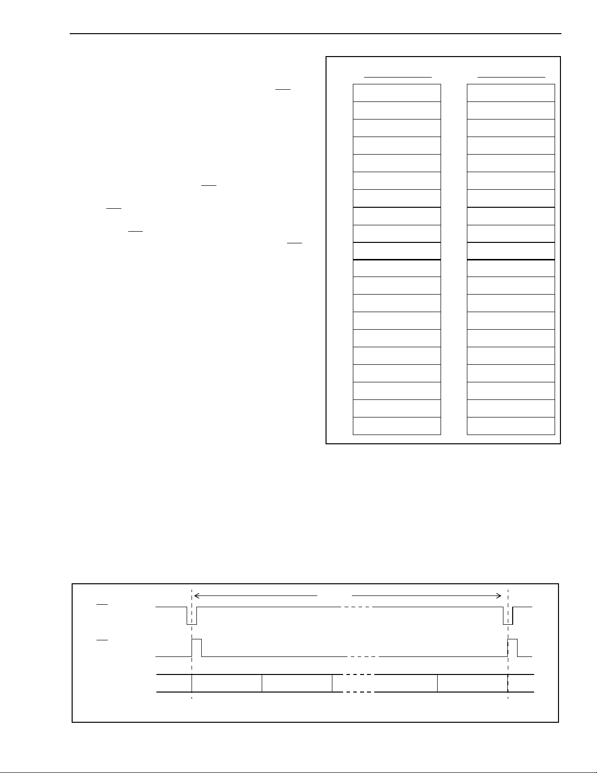
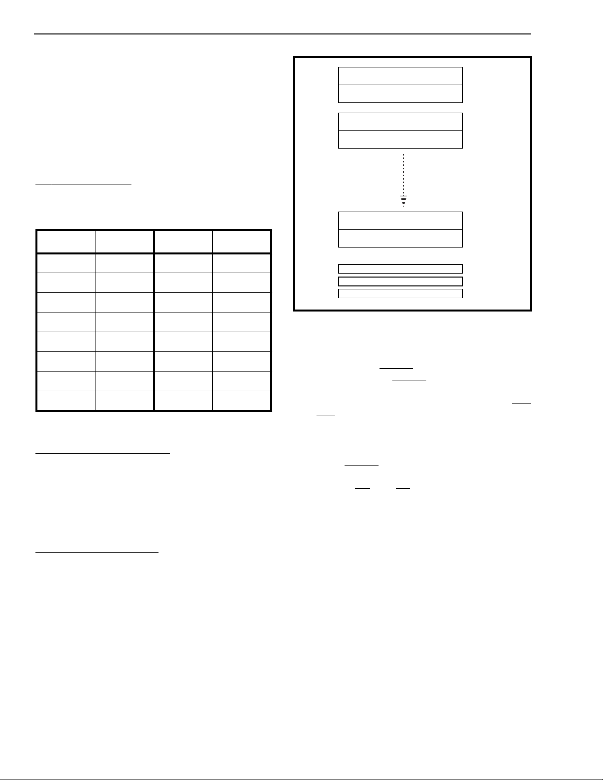
As illustrated in Figure 7, the “per channel” registers
provide independent control and status bits for each
echo canceller. Figure 8 shows the memory map of
the control/status register blocks for all echo
cancellers.
125 µsec
F0i
ST-Bus
F0i
GCI interface
Rin/Sin
Rout/Sout
Note: Refer to Figures 9 and 10 for timing details
Channel 1 Channel 30
Channel 31Channel 0
Figure 6 - ST-BUS and GCI Interface Channel Assignment for 2Mb/s Data Streams
9
Page 10
MT9300 Advance Information
When Extended Delay or Back-to-Back
configuration is selected, Control Register A1/B1 and
Control Register 2 of the selected group of echo
cancellers require special care. Refer to the Register
description section.
Table 2 is a list of the channels used for the 16
groups of echo cancellers when they are configured
as Extended Delay or Back-to-Back
Normal Configuration
For a given group (group 0 to 15), 2 PCM I/O
channels are used. For example, group 1 Echo
Cancellers A and B, channels 2 and 3 are active.
Group Channel Group Channel
Group 0
Echo
Cancellers
Registers
Group 1
Echo
Cancellers
Registers
Groups 2 --> 14
Echo Cancellers
Registers
Group 15
Echo
Cancellers
Registers
Channel 0, EC A Ctrl/Stat Registers
Channel 1, EC B Ctrl/Stat Registers
Channel 2, EC A Ctrl/Stat Registers
Channel 3, EC B Ctrl/Stat Registers
Channel 30, EC A Ctrl/Stat Registers
Channel 31, EC B Ctrl/Stat Registers
0000h -->
0020h -->
0040h -->
0060h -->
03C0h -->
03E0h -->
001Fh
003Fh
005Fh
007Fh
03DFh
03FFh
0 0, 1 8 16, 17
1 2, 3 9 18, 19
2 4, 5 10 20, 21
3 6, 7 11 22, 23
4 8, 9 12 24, 25
5 10, 11 13 26, 27
6 12, 13 14 28, 29
7 14, 15 15 30, 31
Table 2 - Group and Channel allocation
Extended Delay Configuration
For a given group (group 0 to 15), only one PCM I/O
channel is active (Echo Canceller A) and the other
channel carries don’t care data. For example, group
2, Echo Canceller A (Channel 4) will be active and
Echo Canceller B (Channel 5) will carry don’t care
data.
Back-to-Back Configuration
For a given group (group 0 to 15), only one PCM I/O
channel is active (Echo Canceller A) and the other
channel carries don’t care data. For example, group
5, Echo Canceller A (Channel 10) will be active and
Echo Canceller B (Channel 11) will carry don’t care
data.
Main Control Registers <15:0>
Interrupt FIFO Register
Test Register
0400h --> 040Fh
0410h
0411h
Figure 8 - Memory Mapping
Power Up Sequence
On power up, the RESET pin must be held low for
100µs. Forcing the RESET pin low will put the
MT9300 in power down state. In this state, all
internal clocks are halted, D<7:0>, Sout, Rout, DTA
and IRQ pins are tristated. The 16 Main Control
Registers, the Interrupt FIFO Register and the Test
Register are reset to zero.
When the RESET pin returns to logic high and a
valid MCLK is applied, the user must wait 500µs for
PLL to lock. C4i and F0i can be active during this
period. Once the PLL has locked, the user must
power up the 16 groups of echo cancellers
individually, by writing a “1” into the PWUP bit in
each group of echo canceller’s Main Control
Register.
For each group of echo cancellers, when the PWUP
bit toggles from zero to one, echo cancellers A and B
execute their initialization routine. The initialization
routine sets their registers, Base Address+00
Base Address+3FH, to the default Reset Value and
clears the Adaptive Filter coefficients. Two frames
are necessary for the initialization routine to execute
properly.
H
to
10
Once the initialization routine is executed, the user
can set the per channel Control Registers, Base
Address+00
to Base Address+3FH, for the specific
H
application.
Page 11

Advance Information MT9300
Power management
Each group of echo cancellers can be placed in
Power Down mode by writing a “0” into the PWUP bit
in their respective Main Control Register. When a
given group is in Power Down mode, the
corresponding PCM data are bypassed from Rin to
Rout and from Sin to Sout with two frames delay.
Refer to the Main Control Register section for
description.
The typical power consumption can be calculated
with the following equation:
PC = 60 * Nb_of_groups + 40, in mW
where 0 ≤ Nb_of_groups ≤ 16
Call Initialization
To ensure fast initial convergence on a new call, it is
important to clear the Adaptive filter. This is done by
momentarily putting the echo canceller in bypass
mode and then enabling adaptation.
After the HOST CPU has received the channel
number of the interrupt source, the corresponding
per channel Status Register can be read from
internal memory to determine the cause of the
interrupt (see Figure 7 for address mapping of Status
register). The TD bit indicates the presence of a
Tone Disable.
The MIRQ bit 5 in the Main Control Register 0 masks
interrupts from the MT9300. To provide more
flexibility, the MTDBI (bit-4) and MTDAI (bit-3) bits in
the Main Control Register<15:0> allow Tone Disable
to be masked or unmasked, from generating an
interrupt on a per channel basis. Refer to the
Registers Description section.
JTAG Support
The MT9300 JTAG interface conforms to the
Boundary-Scan standard IEEE1149.1. This standard
specifies a design-for-testability technique called
Boundary-Scan test (BST). The operation of the
Boundary Scan circuitry is controlled by an external
Test Access Port (TAP) controller. JTAG inputs are
3.3 Volts compliant only.
Interrupts
The MT9300 provides an interrupt pin (IRQ) to
indicate to the HOST processor when a G.164 or
G.165 Tone Disable is detected and released.
Although the MT9300 may be configured to react
automatically to tone disable status on any input
PCM voice channels, the user may want for the
external HOST processor to respond to Tone Disable
information in an appropriate, application specific
manner.
Each echo canceller will generate an interrupt when
a Tone Disable occurs and will generate another
interrupt when a Tone Disable releases.
Upon receiving an IRQ, the HOST CPU should read
the Interrupt FIFO Register. This register is a FIFO
memory containing the channel number of the echo
canceller that has generated the interrupt.
All pending interrupts from any of the echo
cancellers and their associated input channel
number are stored in this FIFO memory. The
always returns high after a read access to the
Interrupt FIFO Register. The
for each pending interrupt.
IRQ pin will toggle low
IRQ
Test Access Por t (TAP)
The TAP provides access to many test functions of
the MT9300. It consists of three input pins and one
output pin. The following pins are found on the TAP.
• Test Clock Input (TCK)
The TCK provides the clock for the test logic.
The TCK does not interfere with any on-chip
clock and thus remains independent. The TCK
permits shifting of test data into or out of the
Boundary-Scan register cells concurrent with
the operation of the device and without
interfering with the on-chip logic.
• Test Mode Select Input (TMS)
The logic signals received at the TMS input are
interpreted by the TAP Controller to control the
test operations. The TMS signals are sampled
at the rising edge of the TCK pulse. This pin is
internally pulled to VDD when it is not driven
from an external source.
• Test Data Input (TDI)
Serial input data applied to this port is fed
either into the instruction register or into a test
data register, depending on the sequence
previously applied to the TMS input. Both
registers are described in a subsequent
section. The received input data is sampled at
11
Page 12

MT9300 Advance Information
the rising edge of TCK pulses. This pin is
internally pulled to VDDwhen it is not driven from
an external source.
• Test Data Output (TDO)
Depending on the sequence previously applied
to the TMS input, the contents of either the
instruction register or data register are serially
shifted out towards the TDO. The data from the
TDO is clocked on the falling edge of the TCK
pulses. When no data is shifted through the
Boundary Scan cells, the TDO driver is set to a
high impedance state.
• Test Reset (TRST)
This pin is used to reset the JTAG scan
structure. This pin is internally pulled to VSS.
Instruction Register
In accordance with the IEEE 1149.1 standard, the
MT9300 uses public instructions. The JTAG Interface
contains a 3-bit instruction register. Instructions are
serially loaded into the instruction register from the
TDI when the TAP Controller is in its shifted-IR state.
Subsequently, the instructions are decoded to
achieve two basic functions: to select the test data
register that will operate while the instruction is
current, and to define the serial test data register
path, which is used to shift data between TDI and
TDO during data register scanning.
Test Data Registers
As specified in IEEE 1149.1, the MT9300 JTAG
Interface contains three test data registers:
• Boundary-Scan register
The Boundary-Scan register consists of a
series of Boundary-Scan cells arranged to form
a scan path around the boundary of the
MT9300 core logic.
• Bypass Register
The Bypass register is a single stage shift
register that provides a one-bit path from TDI
TDO.
• Device Identification register
The Device Identification register provides
access to the following encoded information:
device version number, par t number and
manufacturer's name.
12
Page 13
Advance Information MT9300
Registers Description
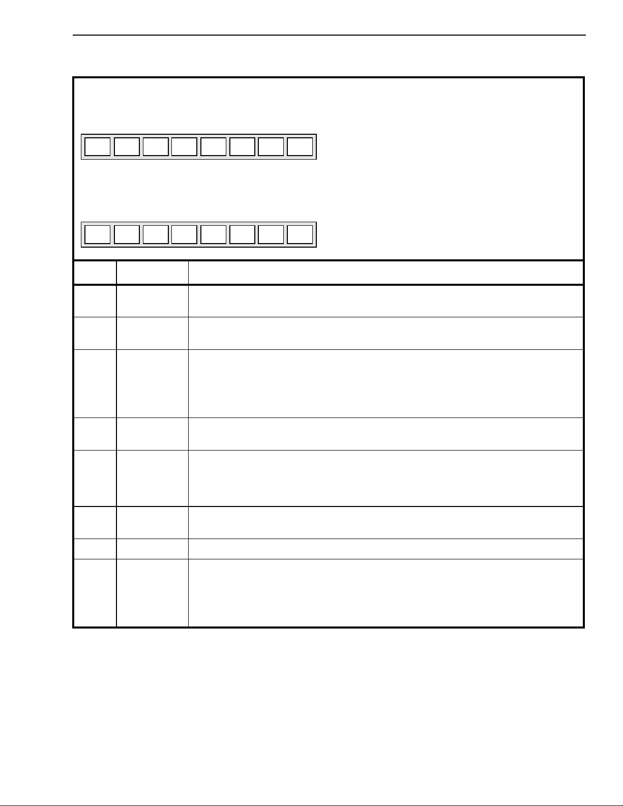
Echo Canceller A, Control Register A1 Read/Write Address: 00H + Base Address
76543210
0AdpDisBypassPADBBMINJDisReset
ExtDl
Echo Canceller B, Control Register B1 Read/Write Address: 20H + Base Address
76543210
1AdpDisBypassPADBBMINJDisReset
0
Bit Name Description
7 Reset When high, the power-up initialization is executed which presets all register bits
including this bit and clears the Adaptive Filter coefficients.
Reset Value: 00H.
Reset Value: 02H.
6 INJDis When high, the noise injection process is disabled. When low noise injection is
enabled.
5 BBM When high the Back to Back configuration is enabled.
When low the Normal configuration is enabled.
Note: Do not enable Extended-Delay and BBM configurations at the same time.
Always setboth BBM bits of the two echo cancellers (Control Register A1 and Control
Register B1) of the same group to the same logic value to avoid conflict.
4 PAD When high, 12dB of attenuation is inserted into the Rin to Rout path.
When low the Rin to Rout path gain is 0dB.
3 Bypass When high, Sin data is by-passed to Sout and Rin data is by-passed to Rout. The
Adaptive Filter coefficients are set to zero and the filter adaptation is stopped.
When low, output data on both Sout and Rout is a function of the echo canceller
algorithm.
2 AdpDis When high, echo canceller adaptation is disabled. The MT9300 cancels echo.
When low, the echo canceller dynamically adapts to the echo path characteristics.
1 0 or 1 Bits marked as “1” or “0” are reserved bits and should be written as indicated.
0 ExtDl
or
0
When high, Echo Cancellers A and B of the same group are internally cascaded into
one 128ms echo canceller.
When low, Echo Cancellers A and B of the same group operate independently.
Note: Do not enable both Extended-Delay and BBM configurations at the same time.
Control Register B1 bit-0 is a reserved bit and should be written “0”.
13
Page 14

MT9300 Advance Information
Echo Canceller A, Control Register 2
Echo Canceller B, Control Register 2
76543210
MuteRMuteSHPFDisNBDisAutoTDNLPDisPHDisTDis
Bit Name Description
7 TDis When high, tone detection is disabled. When low, tone detection is enabled.
When both Echo Cancellers A and B TDis bits are high, Tone Disable processors are
disabled entirely and are put into power down mode.
6 PHDis When high, the tone detectors will trigger upon the presence of a 2100Hz tone
regardless of the presence/absence of periodic phase reversals.
When low, the tone detectors will trigger only upon the presence of a 2100Hz tone
with periodic phase reversals.
5 NLPDis When high, the non-linear processor is disabled.
When low , the non-linear processors function normally. Useful for G.165 conformance
testing.
4 AutoTD When high, the echo canceller puts itself in Bypass mode when the tone detectors
detect the presence of 2100Hz tone. See PHDis for qualification of 2100Hz tones.
When low , the echo canceller algorithm will remain operational regardless of the state
of the 2100Hz tone detectors.
Read/Write Address: 01H + Base Address
Read/Write Address: 21H + Base Address
Reset Value: 00H.
3 NBDis When high, the narrow-band detector is disabled. When low, the narrow-band
detector is enabled.
2 HPFDis When high, the offset nulling high pass filters are bypassed in the Rin and Sin paths.
When low , the offset nulling filters are activ e and will remov e DC offsets on PCM input
signals.
1 MuteS When high, data on Sout is muted to quiet code. When low, Sout carries active code.
0 MuteR When high, data on Rout is muted to quiet code. When low, Rout carries active code.
14
Page 15
Advance Information MT9300
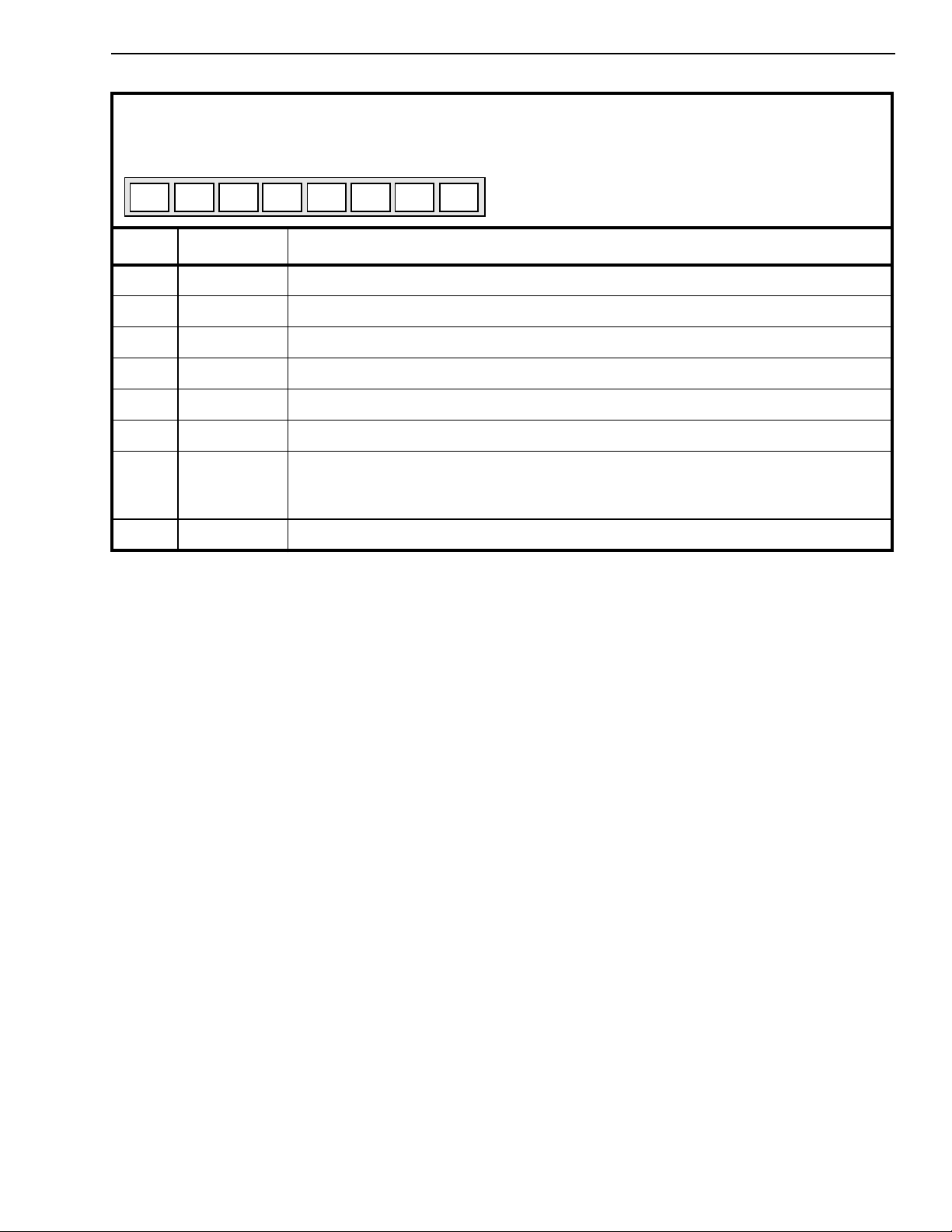
Echo Canceller A, Status Register
Echo Canceller B, Status Register
Read Address: 02H + Base Address
Read Address: 22H + Base Address
76543210
NBTDGresresresDTDetTDres
Reset Value: 00H.
Bit Name Description
7 res Reserved bit.
6 TD Logic high indicates the presence of a 2100Hz tone.
5 DTDet Logic high indicates the presence of a double-talk condition.
4 res Reserved bit.
3 res Reserved bit.
2 res Reserved bit.
1 TDG Tone detection status bit gated with the AutoTD bit.
Logic high indicates that AutoTD has been enabled and the tone detector has
detected the presence of a 2100Hz tone.
0 NB Logic high indicates the presence of a narrow-band signal on Rin.
15
Page 16
MT9300 Advance Information
Echo Canceller A, Flat Delay Register (FD) Read/Write Address: 04h + Base Address
Echo Canceller B, Flat Delay Register (FD) Read/Write Address: 24h + Base Address
76543210
FD
FD
7
FD
6
FD
5
FD
4
FD
3
FD
2
FD
1
0
Power Reset Value
00h
Echo Canceller A, Decay Step Number Register (NS) Read/Write Address: 07h + Base Address
Echo Canceller B, Decay Step Number Register (NS) Read/Write Address: 27h + Base Address
76543210
NS
NS
7
NS
6
NS
5
NS
4
NS
3
NS
2
NS
1
0
Power Reset Value
00h
Echo Canceller A, Decay Step Size Control Register (SSC) Read/Write Address: 06h + Base Address
Echo Canceller B, Decay Step Size Control Register (SSC) Read/Write Address: 26h + Base Address
76543210
0000 SSC2SSC1SSC
Note: Bits marked with “0” are reserved bits and should be written “0”.
Amplitude of MU
1.0
0
0
FIR Filter Length (512 or 1024 taps)
Power Reset Value
04h
Step Size (SS)
Flat Delay (FD
-16
2
7-0
)
Time
Number of Steps (NS
7-0
)
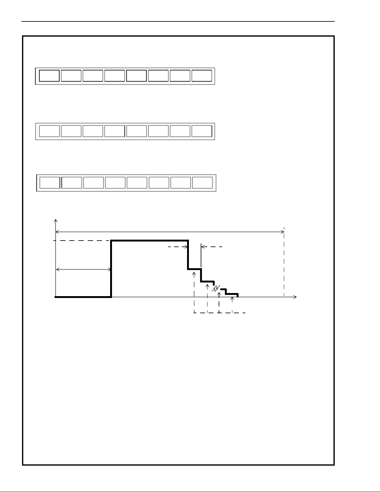
The Exponential Decay registers (Decay Step Number and Decay Step Size) and Flat Delay register allow the LMS adaptation
step-size (MU) to be programmed over the length of the FIR filter. A programmable MU profile allows the performance of the echo
canceller to be optimized for specific applications. For example, if the characteristic of the echo response is known to have a flat
delay of several milliseconds and a roughly exponential decay of the echo impulse response, then the MU profile can be
programmed to approximate this expected impulse response thereby improving the convergence characteristics of the Adaptive
Filter. Note that in the following register descriptions, one tap is equivalent to 125µs (64ms/512 taps).
FD
SSC
NS
7-0
7-0
Flat Delay: This register defines the flat delay of the MU profile, (i.e., where the MU value is 2
as FD
range of FD
0
Decay Step Size Control: This register controls the step size (SS) to be used during the exponential decay of MU. The
2-0
decay rate is defined as a decrease of MU by a factor of 2 every SS taps of the FIR filter, where SS = 4 x2
example; If SSC
is 04h.
x 8 taps. For example; if FD
7-0
is zero.
is: 0 ≤ FD
7-0
= 4, then MU is reduced by a factor of 2 every 64 taps of the FIR filter. The default value of SSC
2-0
= 5, then MU=2
≤ 64 in normal mode and 0 ≤ FD
7-0
7-0
-16
for the first 40 taps of the echo canceller FIR filter. The valid
≤ 128 in extended-delay mode. The default value of FD
7-0
Decay Step Number: This register defines the number of steps to be used for the decay of MU where each step has a
period of SS taps (see SSC
Filter Length (512 or 1024) - [Decay Step Number (NS
For example, if NS
256 taps for a filter length of 512 taps.
=4 and SSC
7-0
). The start of the exponential decay is defined as:
2-0
=4, then the exponential decay start value is 512 - [NS
2-0
) x Step Size (SS)] where SS = 4 x2
7-0
-16
). The delay is defined
SSC
SSC
2-0
.
x SS] = 512 - [4 x (4x24)] =
7-0
2-0
. For
2-0
7-
16
Page 17
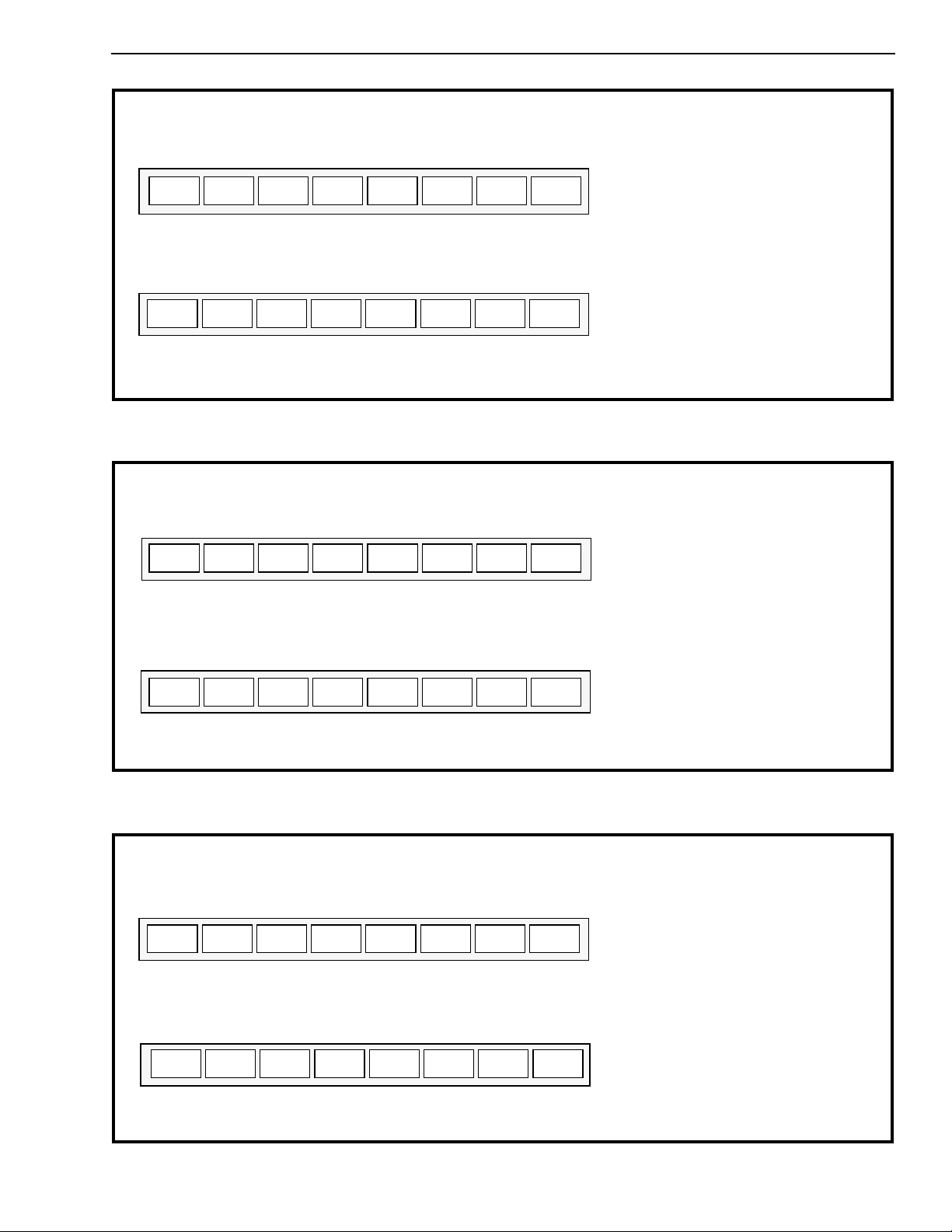
Advance Information MT9300
Echo Canceller A, Rin Peak Detect Register 2 (RP) Read Address: 0Dh + Base Address
Echo Canceller B, Rin Peak Detect Register 2 (RP) Read Address: 2Dh + Base Address
76543210
RP
RP
15
RP
14
RP
13
RP
12
RP
11
10
RP
RP
9
8
Power Reset Value
N/A
Echo Canceller A, Rin Peak Detect Register 1 (RP) Read Address: 0Ch + Base Address
Echo Canceller B, Rin Peak Detect Register 1 (RP) Read Address: 2Ch + Base Address
76543210
RP
These peak detector registers allow the user to monitor the receive in signal (Rin) peak signal lev el. The information is in 16-bit 2’s
complement linear coded format presented in two 8 bit registers for each echo canceller. The high byte is in Register 2 and the low
byte is in Register 1.
RP
7
RP
6
RP
5
RP
4
RP
3
RP
2
RP
1
0
Power Reset Value
N/A
Echo Canceller A, Sin Peak Detect Register 2 (SP) Read Address: 0Fh + Base Address
Echo Canceller B, Sin Peak Detect Register 2 (SP) Read Address: 2Fh + Base Address
76543210
SP
SP
15
SP
14
SP
13
SP
12
SP
11
10
SP
SP
9
8
Power Reset Value
N/A
Echo Canceller A, Sin Peak Detect Register 1 (SP) Read Address: 0Eh + Base Address
Echo Canceller B, Sin Peak Detect Register 1 (SP) Read Address: 2Eh + Base Address
76543210
SP
SP
7
SP
6
SP
5
These peak detector registers allow the user to monitor the send in signal (Sin) peak signal level. The information is in 16-bit 2’s
complement linear coded format presented in two 8 bit registers for each echo canceller. The high byte is in Register 2 and the low
byte is in Register 1.
SP
4
SP
3
SP
2
SP
1
0
Power Reset Value
N/A
Echo Canceller A, Error Peak Detect Register 2 (EP) Read Address: 11h + Base Address
Echo Canceller B, Error Peak Detect Register 2 (EP) Read Address: 31h + Base Address
76543210
EP
EP
15
EP
14
EP
13
EP
12
EP
11
10
EP
EP
9
8
Power Reset Value
N/A
Echo Canceller A, Error Peak Detect Register 1 (EP) Read Address: 10h + Base Address
Echo Canceller B, Error Peak Detect Register 1 (EP) Read Address: 30h + Base Address
76543210
EP
EP
7
EP
6
EP
5
EP
4
EP
3
EP
2
EP
1
0
Power Reset Value
N/A
These peak detector registers allow the user to monitor the error signal peak level. The information is in 16-bit 2’s complement
linear coded format presented in two 8 bit registers for each echo canceller. The high byte is in Register 2 and the low byte is in
Register 1.
17
Page 18
MT9300 Advance Information
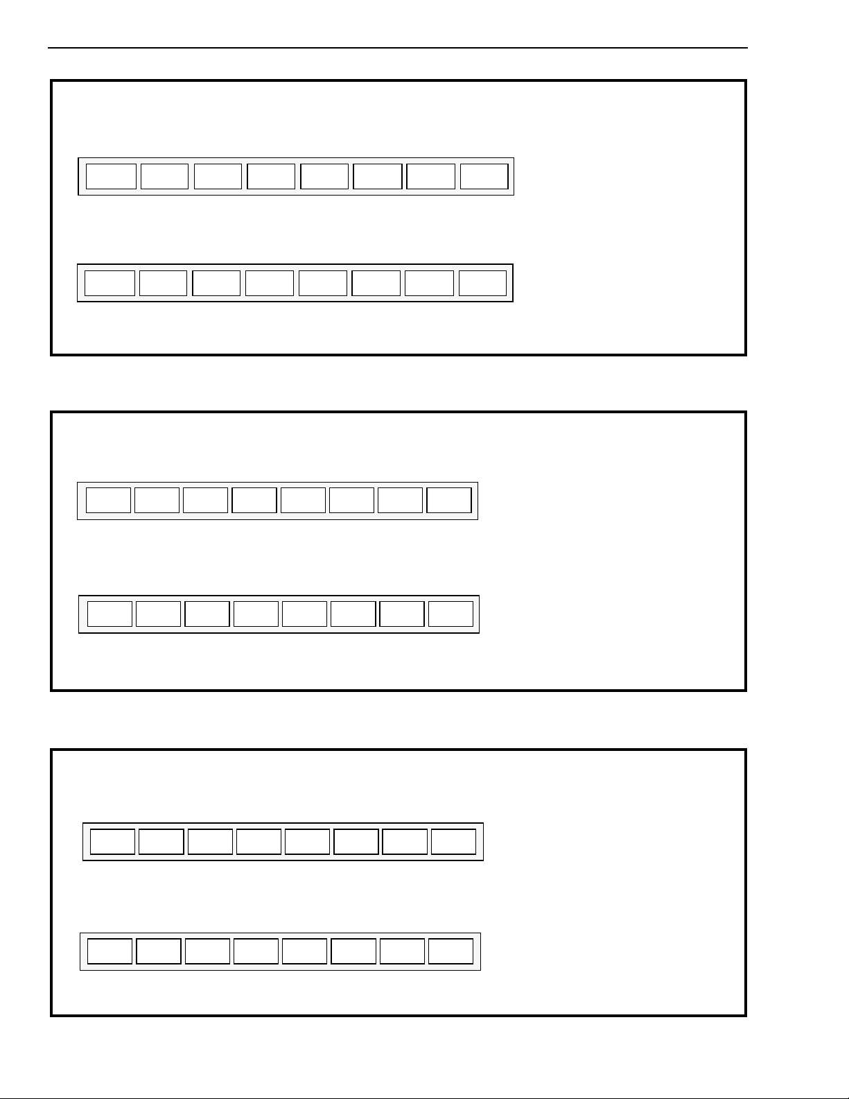
Echo Canceller A, Double-Talk Detection Threshold Register 2 Read/Write Address: 15h + Base Address
Echo Canceller B, Double-Talk Detection Threshold Register 2 Read/Write Address: 35h + Base Address
7654 3 2 1 0
DTDT15DTDT14DTDT13DTDT
DTDT
12
DTDT10DTDT9DTDT
11
8
(DTDT)
Power Reset Value
48h
Echo Canceller A, Double-Talk Detection Threshold Register 1 Read/Write Address: 14h + Base Address
Echo Canceller B, Double-Talk Detection Threshold Register 1
7 6543 21 0
DTDT7DTDT6DTDT5DTDT
This register allows the user to program the level of Double-Talk Detection Threshold (DTDT). The 16 bit 2’s complement linear
value defaults to 4800h= 0.5625 or -5dB. The maximum value is 7FFFh = 0.9999 or 0 dB. The high byte is in Register 2 and
the low byte is in Register 1.
DTDT
4
DTDT2DTDT1DTDT
3
Read/Write Address: 34h + Base Address
Power Reset Value
0
(DTDT)
00h
Echo Canceller A, Non-Linear Processor Threshold Register 2 Read/Write Address: 19h + Base Address
Echo Canceller B, Non-Linear Processor Threshold Register 2 Read/Write Address: 39h + Base Address
76543210
NLP15NLP14NLP
NLP
13
NLP
12
NLP
11
NLP
10
NLP
9
8
(NLPTHR)
Power Reset Value
0Bh
Echo Canceller A, Non-Linear Processor Threshold Register 1 Read/Write Address: 18h + Base Address
Echo Canceller B, Non-Linear Processor Threshold Register 1 Read/Write Address: 38h + Base Address
76543210
NLP7NLP
This register allows the user to program the lev el of the Non-Linear Processor Threshold (NLPTHR). The 16 bit 2’s complement
linear value defaults to 0B60h = 0.0889 or -21.0dB. The maximum value is 7FFFh = 0.9999 or 0 dB. The high byte is in
Register 2 and the low byte is in Register 1.
6
NLP5NLP
NLP
4
NLP
3
NLP
2
NLP
1
(NLPTHR)
0
Power Reset Value
60h
Echo Canceller A, Adaptation Step Size (MU) Register 2 Read/Write Address: 1Bh + Base Address
Echo Canceller B, Adaptation Step Size (MU) Register 2 Read/Write Address: 3Bh + Base Address
76543210
MU
MU
15
MU
14
MU
13
MU
12
MU
11
MU
10
MU
9
8
(MU)
Power Reset Value
40h
Echo Canceller A, Adaptation Step Size (MU) Register 1 Read/Write Address: 1Ah + Base Address
Echo Canceller B, Adaptation Step Size (MU) Register 1 Read/Write Address: 3Ah + Base Address
76543210
MU
MU
7
MU
6
MU
5
MU
4
MU
3
MU
2
MU
1
0
(MU)
Power Reset Value
00h
This register allows the user to program the level of MU. MU is a 16 bit 2’s complement value which defaults to 4000h = 1.0
The maximum value is 7FFFh or 1.9999 decimal. The high byte is in Register 2 and the low byte is in Register 1.
18
Page 19

Advance Information MT9300
Main Control Register 0 (EC group 0) Read/Write Address: 400
H
76543210
PWUPLAWFormatMTDAIMTDBIMIRQODEWR_all
Reset Value: 00H.
Bit Name Description
7 WR_all Write all control bit: When high, Group 0-15 Echo Cancellers Registers are mapped
into 0000h to 003F which is Group 0 address mapping. Useful to initialize the 16
Groups of Echo Cancellers as per Group 0.
When low, address mapping is per Figure 8.
Note: Only the Main Control Register 0 has the WR_all bit.
6 ODE Output Data Enable: This control bit is logically AND’d with the ODE input pin. When
both ODE bit and ODE input pin are high, the Rout and Sout outputs are enabled.
When the ODE bit is low or the ODE input pin is low, the Rout and Sout outputs are
high impedance.
Note: Only the Main Control Register 0 has the ODE bit.
5 MIRQ Mask Interrupt: When high, all the interrupts from the Tone Detectors output are
masked. The Tone Detectors operate as specified in their Echo Canceller B, Control
Register 2.
When low, the Tone Detectors Interrupts are active.
Note: Only the Main Control Register 0 has the MIRQ bit.
4 MTDBI Mask Tone Detector B Interrupt: When high, the Tone Detector interrupt output from
Echo Canceller B is masked. The Tone Detector operates as specified in Echo
Canceller B, Control Register 2.
When low, the Tone Detector B Interrupt is active.
3 MTDAI Mask Tone Detector A Interrupt: When high, the Tone Detector interrupt output from
Echo Canceller A is masked. The Tone Detector operates as specified in Echo
Canceller A, Control Register 2.
When low, the Tone Detector A Interrupt is active.
2 Format ITU-T/Sign Mag: When high, both Echo Cancellers A and B for a given group, accept
ITU-T (G.711) PCM code.
When low, both Echo Cancellers A and B for a given group, accept sign-magnitude
PCM code.
1LAWA/µ Law: When high, both Echo Cancellers A and B for a given group, accept A-Law
companded PCM code.
When low, both Echo Cancellers A and B for a given group, accept µ-Law companded
PCM code.
0 PWUP Power-UP: When high, both Echo Cancellers A and B and Tone Detectors for a given
group, are active.
When low, both Echo Cancellers A and B and Tone Detectors for a given group, are
placed in Pow er Down mode . In this mode, the correspondingPCM data are bypassed
from Rin to Rout and from Sin to Sout with two frames delay.
When the PWUP bit toggles from zero to one, the echo canceller A and B ex ecute their
initialization routine which presets their registers, Base Address+00H to Base
Address+3FH, to default Reset Value and clears the Adaptive Filter coefficients.
Two frames are necessary for the initialization routine to execute properly. Once the
initialization routine is executed, the user can set the per channel Control Registers for
their specific application.
19
Page 20
MT9300 Advance Information
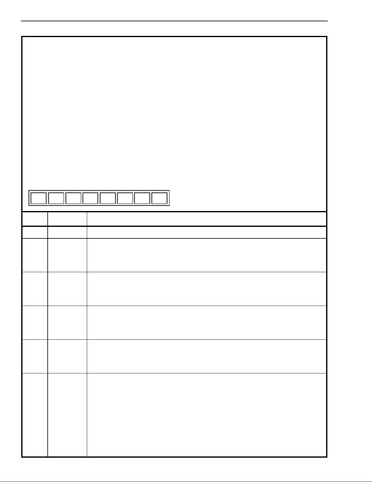
Main Control Register 1 (EC group 1) Read/Write Address: 401
Main Control Register 2 (EC group 2) Read/Write Address: 402
Main Control Register 3 (EC group 3) Read/Write Address: 403
Main Control Register 4 (EC group 4) Read/Write Address: 404
Main Control Register 5 (EC group 5) Read/Write Address: 405
Main Control Register 6 (EC group 6) Read/Write Address: 406
Main Control Register 7 (EC group 7) Read/Write Address: 407
Main Control Register 8 (EC group 8) Read/Write Address: 408
Main Control Register 9 (EC group 9) Read/Write Address: 409
Main Control Register 10 (EC group 10) Read/Write Address: 40A
Main Control Register 11 (EC group 11) Read/Write Address: 40B
Main Control Register 12 (EC group 12) Read/Write Address: 40C
Main Control Register 13 (EC group 13) Read/Write Address: 40D
Main Control Register 14 (EC group 14) Read/Write Address: 40E
Main Control Register 15 (EC group 15) Read/Write Address: 40F
76543210
PWUPLAWFormatMTDAIMTDBIunusedunusedunused
Reset Value: 00H.
Bit Name Description
H
H
H
H
H
H
H
H
H
H
H
H
H
H
H
7-5 unused Unused Bits.
4 MTDBI Mask Tone Detector B Interrupt: When high, the Tone Detector interrupt output from
Echo Canceller B is masked. The Tone Detector operates as specified in Echo
Canceller B, Control Register 2.
When low, the Tone Detector B Interrupt is active.
3 MTDAI Mask Tone Detector A Interrupt: When high, the Tone Detector interrupt output from
Echo Canceller A is masked. The Tone Detector operates as specified in Echo
Canceller A, Control Register 2.
When low, the Tone Detector A Interrupt is active.
2 Format ITU-T/Sign Mag: When high, both Echo Cancellers A and B for a given group, select
ITU-T (G.711) PCM code.
When low, both Echo Cancellers A and B for a given group, select sign-magnitude
PCM code.
1LAWA/µ Law: When high, both Echo Cancellers A and B for a given group, select A-Law
companded PCM code.
When low, both Echo Cancellers A and B for a given group, select m-Law companded
PCM code.
0 PWUP Power-UP: When high, both Echo Cancellers A and B and Tone Detectors for a given
group, are active.
When low, both Echo Cancellers A and B and Tone Detectors for a given group, are
placed in Pow er Down mode . In this mode, the correspondingPCM data are bypassed
from Rin to Rout and from Sin to Sout with two frames delay.
When the PWUP bit toggles from zero to one, the echo cancellers A and B execute
their initialization routine which presets their registers, Base Address+00H to Base
Address+3FH, to default Reset Value and clears the Adaptive Filter coefficients.
Two frames are necessary for the initialization routine to execute properly. Once the
initialization routine is executed, the user can set the per channel Control Registers for
their specific application.
20
Page 21
Advance Information MT9300
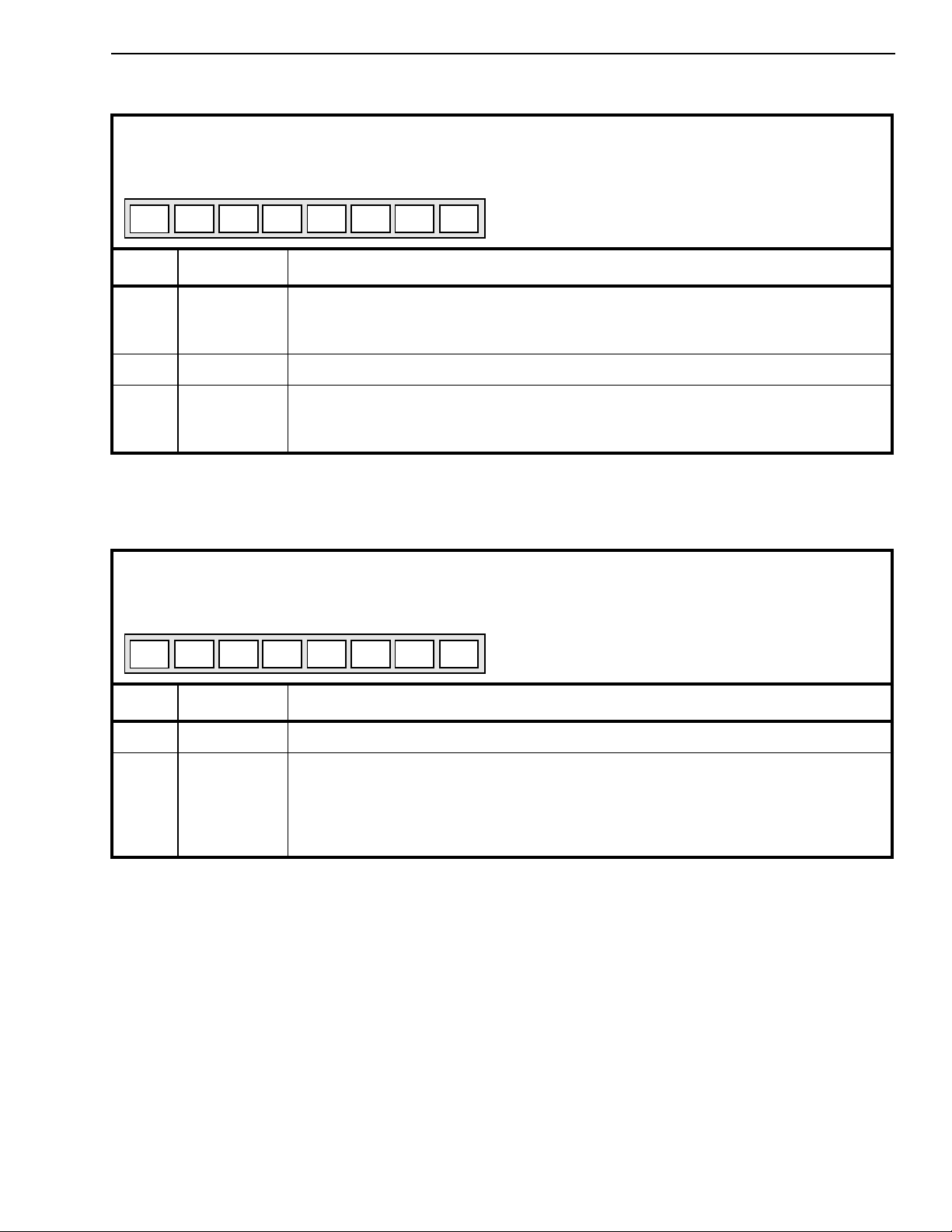
Interrupt FIFO Register
Read Address: 410H (Read only)
76543210
I0I1I2I3I400IRQ
Reset Value: 00H.
Bit Name Description
7 IRQ Logic high indicates an interrupt has occurred. IRQ bit is cleared after the Interrupt
FIFO register is read.
Logic Low indicates that no interrupt is pending and the FIFO is empty.
6:5 0 Unused bits. Always zero
4:0 I<4:0> I<4:0> binary code indicates the channel number at which a Tone Detector state
change has occurred.
Note: Whenever a Tone Disable is detected or released, an interrupt is generated.
Test Register
Read/Write Address: 411
H
76543210
Tirqresresresresresresres
Reset Value: 00H.
Bit Name Description
7:1 res Reserved bits. Must always be set to zero for normal operation.
0 Tirq Test IRQ: Useful for the application engineer to verify the interrupt service routine.
When high, any change to MTDBI and MTDAI bits of the Main Control Register will
cause an interrupt and its corresponding channel number will be available from the
Interrupt FIFO Register.
When low, normal operation is selected.
21
Page 22
MT9300 Advance Information
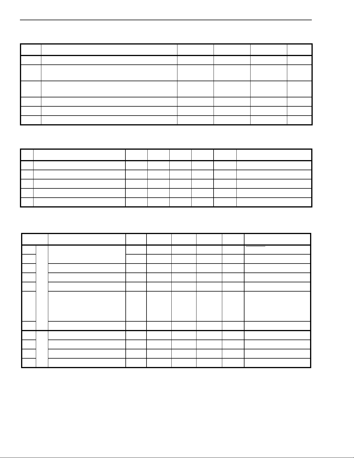
Absolute Maximum Ratings*
Parameter Symbol Min Max Units
1 Supply Voltage V
2 Voltage on any 3.3V I/O pins (other than supply
V
DD
I3
-0.3 5.0 V
VSS - 0.3 VDD+0.5 V
pins)
3 Voltage on any 5V Tolerant I/O pins (other than sup-
V
I5
VSS - 0.3 5.5 V
ply pins)
4 Continuous Current at digital outputs I
5 Package power dissipation P
6 Storage temperature T
* Exceeding these values may cause permanent damage. Functional operation under these conditions is not implied.
o
D
S
-55 150 °C
20 mA
2.0 W
Recommended Operating Conditions - Voltages are with respect to ground (Vss) unless otherwise stated.
Characteristics Sym Min Typ
1 Operating Temperature T
2 Positive Supply V
3 Input High Voltage on 3.3V tolerant V
4 Input High Voltage on 5V tolerant V
5 Input Low Voltage V
‡ Typical figures are at 25
DC Electrical Characteristics
°C and are for design aid only: not guaranteed and not subject to production testing
†
- Voltages are with respect to ground (Vss) unless otherwise stated.
Characteristics Sym Min Typ
OP
DD
IH3
IH5
IL
-40 +85 °C
3.0 3.3 3.6 V
0.7V
DD
0.7V
DD
‡
Max Units Test Conditions
V
DD
V
5.5 V
0.3V
DD
‡
Max Units Test Conditions
V
1
2 Power Consumption P
3 Input High Voltage V
4 Input Low Voltage V
5 Input Leakage
Supply Current I
I
N
P
U
T
S
Input Leakage on Pullup
Input Leakage on Pulldown
CC
I
DD
IIH/I
I
LU
I
LD
250 µA RESET = 0
308 375 mA All channels active
C
0.7V
IH
IL
IL
DD
1.0 1.35 W All channels active
V
-30
30
0.3V
10
-55
65
DD
V
µA
VIN=VSS to VDD or 5.5V
µA
VIN=V
VIN=V
SS
DD
µA
See Note 1
6 Input Pin Capacitance C
O
7
8 Output Low Voltage V
9 High Impedance Leakage I
10 Output Pin Capacitance C
† Characteristics are over recommended operating conditions unless otherwise stated
‡ Typical figures are at 25°C, VDD=3.3V and are for design aid only: not guaranteed and not subject to production testing.
* Note 1: Maximum leakage on pins (output or I/O pins in high impedance state) is over an applied voltage (VIN).
Output High Voltage V
U
T
P
U
T
S
OH
OL
OZ
I
0.8V
DD
O
10 pF
VIOH = 12 mA
0.4 V IOL = 12 mA
10 µAVIN=VSS to 5.5V
10 pF
22
Page 23
Advance Information MT9300
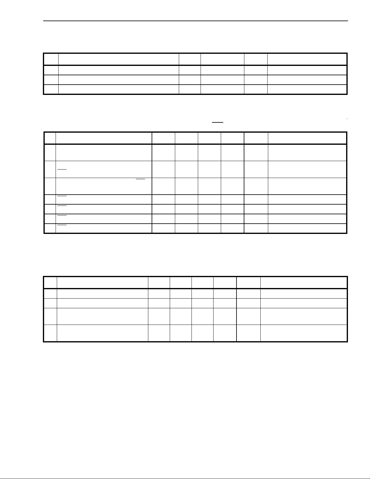
AC Electrical Characteristics† - Timing Parameter Measurement Voltage Levels
- Voltages are with respect to ground (Vss) unless otherwise stated.
Characteristics Sym Level Units Conditions
1 CMOS Threshold V
2 CMOS Rise/Fall Threshold Voltage High V
3 CMOS Rise/Fall Threshold Voltage Low V
† Characteristics are over recommended operating conditions unless otherwise stated
TT
HM
LM
0.5V
0.7V
0.3V
DD
DD
DD
V
V
V
AC Electrical Characteristics†- Frame Pulse and C4i
Characteristic Sym Min Typ
1 Frame pulse width (ST-BUS, GCI)
2 Frame Pulse Setup time before
t
FPW
t
FPS
20 2*
10 122 150 ns
C4i falling (ST-BUS or GCI)
3 Frame Pulse Hold Time from C4i
t
FPH
10 122 150 ns
falling (ST-BUS or GCI)
4 C4i Period
5 C4i Pulse Width High
6 C4i Pulse Width Low
7 C4i Rise/Fall Time
† Characteristics are over recommended operating conditions unless otherwise stated
‡ Typical figures are at 25°C, VDD=3.3V and for design aid only: not guaranteed and not subject to production testing
t
t
t
tr, t
CP
CH
CL
190 244.1 300 ns
85 150 ns
85 150 ns
f
‡
Max Units Notes
ns
t
-20
CP
10 ns
i
AC Electrical Characteristics†- Serial Streams for ST-BUS and GCI Backplanes
Characteristic Sym Min Typ
1 Rin/Sin Set-up Time
2 Rin/Sin Hold Time
3 Rout/Sout Delay
t
t
t
SIS
SIH
SOD
10 ns
10 ns
- Active to Active
4 Output Data Enable (ODE)
t
ODE
Delay
† Characteristics are over recommended operating conditions unless otherwise stated
‡ Typical figures are at 25°C, VDD=3.3V and for design aid only: not guaranteed and not subject to production testing
* Note1: High Impedance is measured by pulling to the appropriate rail with RL, with timing corrected to cancel time taken to discharge CL.
‡
Max Units Test Conditions
60 ns CL=150pF
30 ns CL=150pF, RL=1K
See Note 1
23
Page 24
MT9300 Advance Information
t
FPW
F0i
C4i
Rout/Sout
Rin/Sin
F0i
C4i
t
t
FPS
FPH
t
SOD
Bit 0, Channel 31 Bit 7, Channel 0 Bit 6, Channel 0 Bit 5, Channel 0
t
SIS
Bit 0, Channel 31
t
CP
t
SIH
Bit 7, Channel 0 Bit 6, Channel 0 Bit 5, Channel 0
t
CH
t
CL
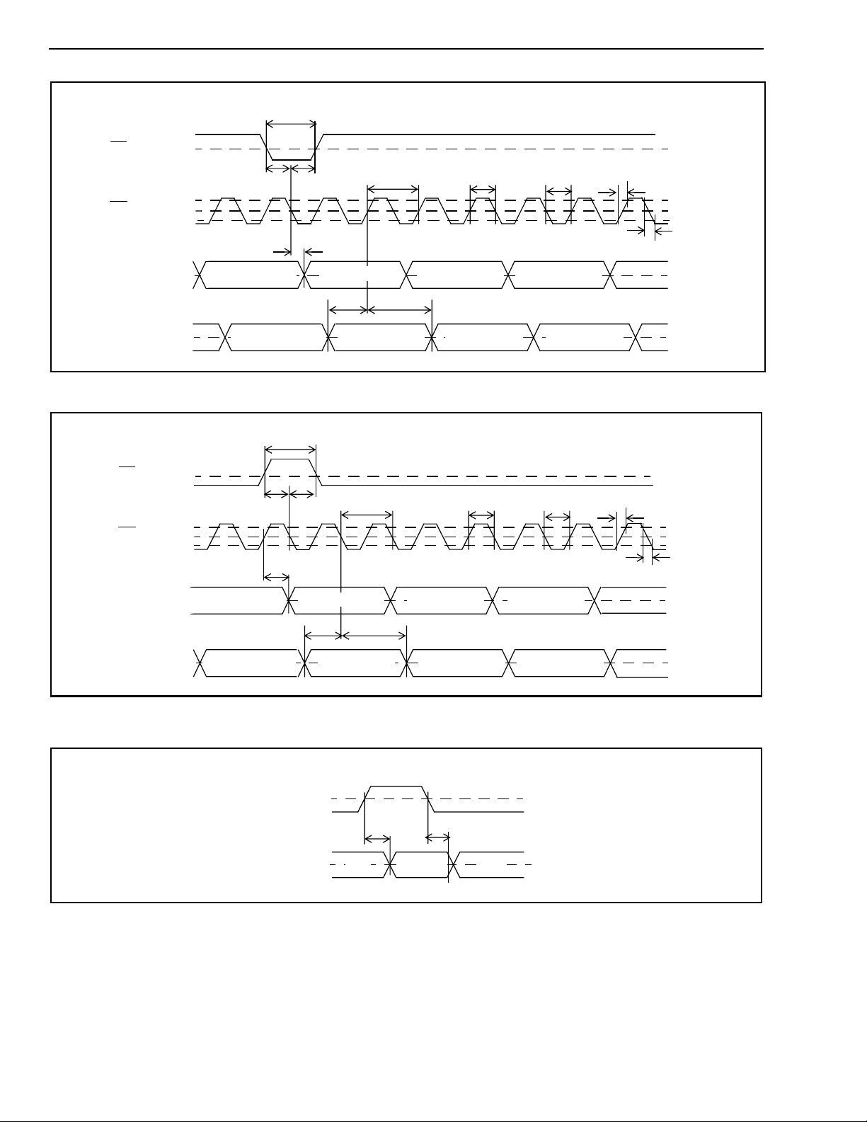
Figure 9 - ST-BUS Timing at 2.048 Mb/s
t
FPW
t
FPS
t
SOD
t
FPH
t
CP
t
CH
t
CL
V
TT
t
r
V
HM
V
TT
V
LM
t
f
V
TT
V
TT
V
TT
t
r
V
HM
V
TT
V
LM
t
f
Sout/Rout
Sin/Rin
Bit 7, Channel 31) Bit 0, Channel 0 Bit 1, Channel 0 Bit 2, Channel 0
Bit 7, Channel 31)
t
SIS
t
SIH
Bit 0, Channel 0 Bit 1, Channel 0 Bit 2, Channel 0
Figure 10 - GCI Interface Timing at 2.048 Mb/s
V
ODE
Sout/Rout
HiZ
t
ODE
Valid Data
t
ODE
HiZ
TT
V
TT
Figure 11 - Output Driver Enable (ODE)
V
TT
V
TT
24
Page 25
Advance Information MT9300
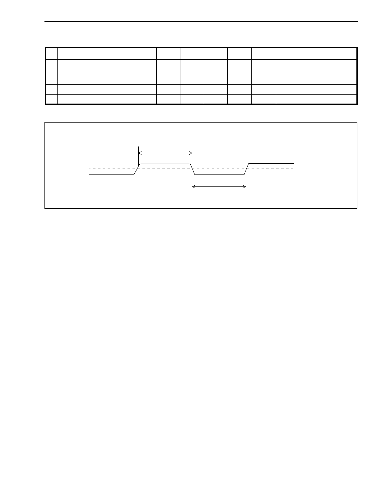
AC Electrical Characteristics†- Master Clock - Voltages are with respect to ground (V
Characteristic Sym Min Typ
‡
Max Units Notes
SS
1 Master Clock Frequency,
- Fsel = 0
- Fsel = 1
2 Master Clock Low
3 Master Clock High
† Characteristics are over recommended operating conditions unless otherwise stated
‡ Typical figures are at 25°C, VDD=3.3V and for design aid only: not guaranteed and not subject to production testing
t
MCH
MCLK
f
MCF0
f
MCF1
t
MCL
t
MCH
19.0
9.5
20.0
10.0
21.0
10.5
20 ns
20 ns
t
MCL
MHz
MHz
V
Figure 12 - Master Clock
). unless otherwise stated.
TT
25
Page 26
MT9300 Advance Information
AC Electrical Characteristics†- Motorola Non-Multiplexed Bus Mode
Characteristics Sym Min Typ
‡
Max Units Test Conditions
1 CS setup from DS falling t
2R/W setup from DS falling t
3 Address setup from DS falling t
4 CS hold after DS rising t
5R/W hold after DS rising t
6 Address hold after DS rising t
7 Data delay on read t
8 Data hold on read t
CSS
RWS
ADS
CSH
RWH
ADH
DDR
DHR
0ns
0ns
0ns
0ns
0ns
0ns
79 ns CL=150pF, RL=1K
315nsC
=150pF, RL=1K
L
See Note 1
9 Data setup on write t
10 Data hold on write t
11 Acknowledgment delay t
12 Acknowledgment hold time t
DSW
DHW
AKD
AKH
0ns
0ns
80 ns CL=150pF, RL=1K
0 8 ns CL=150pF, RL=1K,
See Note 1
13 IRQ delay t
IRD
20 65 ns CL=150pF, RL=1K,
See Note 1
† Characteristics are over recommended operating conditions unless otherwise stated
‡ Typical figures are at 25°C, VDD=3.3V and for design aid only: not guaranteed and not subject to production testing
* Note 1:High Impedance is measured by pulling to the appropriate rail with RL, with timing corrected to cancel time taken to discharge CL.
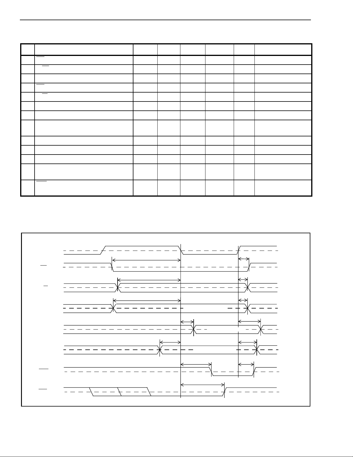
DS
CS
R/W
A0-A10
D0-D7
READ
D0-D7
WRITE
DTA
IRQ
t
CSS
t
RWS
t
ADS
VALID ADDRESS
t
DDR
VALID READ DATA
t
DSW
VALID WRITE DATA
t
AKD
t
IRD
Figure 13 - Motorola Non-Multiplexed Bus Timing
t
DHW
t
t
DHR
t
CSH
RWH
t
ADH
t
AKH
V
TT
V
TT
V
TT
V
TT
V
TT
V
TT
V
TT
V
TT
26
Page 27

Package Outlines
L1
A
A
2
Pin 1
Index
A
1
D
D
1
e
E
E
1
WARNING:
This package diagram does not apply to the MT90810AK
100 Pin Package. Please refer to the data sheet for
exact dimensions.
b
L
Notes:
1) Not to scale
2) Top dimensions in inches
3) The governing controlling
dimensions are in millimeters
for design purposes ( )
Metric Quad Flat Pack - L Suffix
Dim
Min Max Min Max Min Max Min Max
A - 0.096
(2.45)
A1 0.01
(0.25)
44-Pin 64-Pin 100-Pin 128-Pin
A2 0.077
(1.95)
b 0.01
(0.30)
D 0.547 BSC
(13.90 BSC)
D
1
E 0.547 BSC
E
1
e 0.031 BSC
L 0.029
L1 0.077 REF
0.394 BSC
(10.00 BSC)
(13.90 BSC)
0.394 BSC
(10.00 BSC)
(0.80 BSC)
(0.73)
(1.95 REF)
0.083
(2.10)
0.018
(0.45)
(1.03)
- 0.01
0.04
- 0.134
(0.25)
0.1
(2.55)
0.013
(0.35)
0.941 BSC
(23.90 BSC)
0.787 BSC
(20.00 BSC)
0.705 BSC
(17.90 BSC)
0.551 BSC
(14.00 BSC)
0.039 BSC
(1.0 BSC)
0.029
(0.73)
0.077 REF
(1.95 REF)
(3.40)
- 0.01
0.12
(3.05)
0.02
(0.50)
0.04
(1.03)
- 0.134
(0.25)
0.1
(2.55)
0.009
(0.22)
0.941 BSC
(23.90 BSC)
0.787 BSC
(20.00 BSC)
0.705 BSC
(17.90 BSC)
0.551 BSC
(14.00 BSC)
0.256 BSC
(0.65 BSC)
0.029
(0.73)
0.077 REF
(1.95 REF)
- 0.154
(3.40)
- 0.00 0.01
0.12
(3.05)
0.015
(0.38)
0.04
(1.03)
0.125
(3.17)
0.019
(0.30)
1.23 BSC
(31.2 BSC)
1.102 BSC
(28.00 BSC)
1.23 BSC
(31.2 BSC)
1.102 BSC
(28.00 BSC)
0.031 BSC
(0.80 BSC)
0.029
(0.73)
0.063 REF
(1.60 REF)
(3.85)
(0.25)
0.144
(3.60)
0.018
(0.45)
0.04
(1.03)
NOTE: Governing controlling dimensions in parenthesis ( ) are in millimeters.
Page 28

Package Outlines
Dim
Min Max Min Max Min Max
A - 0.154
(3.92)
A1 0.01
(0.25)
160-Pin 208-Pin 240-Pin
A2 0.125
(3.17)
b 0.009
(0.22)
D 1.23 BSC
(31.2 BSC)
D
1
E 1.23 BSC
E
1
e 0.025 BSC
L 0.029
L1 0.063 REF
1.102 BSC
(28.00 BSC)
(31.2 BSC)
1.102 BSC
(28.00 BSC)
(0.65 BSC)
(0.73)
(1.60 REF)
0.144
(3.67)
0.015
(0.38)
0.04
(1.03)
0.01
(0.25)
.126
(3.20)
.007
(0.17)
0.018
(0.45)
1.204
(30.6)
1.102
(28.00)
1.204 BSC
(30.6 BSC)
1.102 BSC
(28.00 BSC)
0.020 BSC
(0.50 BSC)
0.051 REF
(1.30 REF)
.161
(4.10)
0.02
(0.50)
.142
(3.60)
.011
(0.27)
0.029
(0.75)
- 0.161
0.01
(0.25)
0.126
(3.2)
0.007
(0.17)
1.360 BSC
(34.6 BSC)
1.26 BSC
(32.00 BSC)
1.360 BSC
(34.6 BSC)
1.26 BSC
(32.00 BSC)
0.0197 BSC
(0.50 BSC)
0.018
(0.45)
0.051 REF
(1.30 REF)
(4.10)
0.02
(0.50)
0.142
(3.60)
0.010
(0.27)
0.029
(0.75)
NOTE: Governing controlling dimensions in parenthesis ( ) are in millimeters.
Page 29

http://www.mitelsemi.com
World Headquarters - Canada
Tel: +1 (613) 592 2122
Fax: +1 (613) 592 6909
North America Asia/Pacific Europe, Middle East,
Tel: +1 (770) 486 0194 Tel: +65 333 6193 and Africa (EMEA)
Fax: +1 (770) 631 8213 Fax: +65 333 6192 Tel: +44 (0) 1793 518528
Fax: +44 (0) 1793 518581
Information relating to products and services furnished herein by Mitel Corporation or its subsidiaries (collectively “Mitel”) is believed to be reliable. However, Mitel assumes no
liability for errors that may appear in this publication, or for liability otherwise arising from the application or use of any such information, product or service or for any infringement of
patents or other intellectual property rights owned by third parties which may result from such application or use. Neither the supply of such information or purchase of product or
service conveys any license, either express or implied, under patents or other intellectual property rights owned by Mitel or licensed from third parties by Mitel, whatsoever.
Purchasers of products are also hereby notified that the use of product in certain ways or in combination with Mitel, or non-Mitel furnished goods or services may infringe patents or
other intellectual property rights owned by Mitel.
This publication is issued to provide information only and (unless agreed by Mitel in writing) may not be used, applied or reproduced for any purpose nor form part of any order or
contract nor to be regarded as a representation relating to the products or services concerned. The products, their specifications, services and other information appearing in this
publication are subject to change by Mitel without notice. No warranty or guarantee express or implied is made regarding the capability, performance or suitability of any product or
service. Information concerning possible methods of use is provided as a guide only and does not constitute any guarantee that such methods of use will be satisfactory in a specific
piece of equipment. It is the user’s responsibility to fully determine the performance and suitability of any equipment using such information and to ensure that any publication or
data used is up to date and has not been superseded. Manufacturing does not necessarily include testing of all functions or parameters. These products are not suitable for use in
any medical products whose failure to perform may result in significant injury or death to the user. All products and materials are sold and services provided subject to Mitel’s
conditions of sale which are available on request.
M Mitel (design) and ST-BUS are registered trademarks of MITEL Cor poration
Mitel Semiconductor is an ISO 9001 Registered Company
Copyright 1999 MITEL Corporation
All Rights Reserved
Printed in CANADA
TECHNICAL DOCUMENTATION - NOT FOR RESALE
 Loading...