

Page 1
ISO-CMOS ST-BUS FAMILY
MT8940
T1/CEPT Digital Trunk PLL
Features
• Provides T 1 clock at 1. 544 MHz lo ck ed t o input
frame pul se
• Sources CEPT (30+ 2) Digi tal Trunk/ST-BUS
clock and timing signals locked to internal or
external 8 k Hz si gnal
• TTL compa tibl e logic inputs and o utpu ts
• Uncommitted 2-inpu t NAND g ate
• Single 5 vol t pow er suppl y
• Low power IS O-CM OS te chnol ogy
Applications
• Synchronization and timing control for T1
and CEPT digi tal trun k tran smissi on lin ks
• ST- BUS clock and fr ame pulse so urce
ISSUE 7 July 1993
Ordering Information
MT8940AC 24 Pin Ce r am i c D IP
MT8940AE 24 Pin Pla stic D IP
-40°C to + 85°C
Description
The MT8940 is a dual digital phase-locked loop
providing the timing and synchronization signals for
the T1 or CEPT transmission links and the ST-BUS.
The first PLL provides the T1 clock (1.544 MHz)
synchronized to the input frame pulse at 8 kHz. The
timing sign a l s fo r the CEPT transmis s ion li nk an d th e
ST-BUS are provided by the second PLL locked to
an internal or an external 8 kHz frame pulse signal.
The MT8940 is fabricated in MITEL’s ISO-CMOS
technology.
F0i
C12i
MS0
MS1
MS2
MS3
C8Kb
C16i
DPLL #1
2:1 MUX
Mode
Selection
Logic
DPLL #2
Ai
Bi
Yo V
DD
Input
Selector
Clock
Generator
V
SS
RST
Variable
Clock
Control
Frame Pulse
Control
4.096 MHz
Clock
Control
2.048 MHz
Clock
Control
CVb
CV
ENCV
F0b
C4b
C4o
ENC4o
C2o
C2o
ENC2o
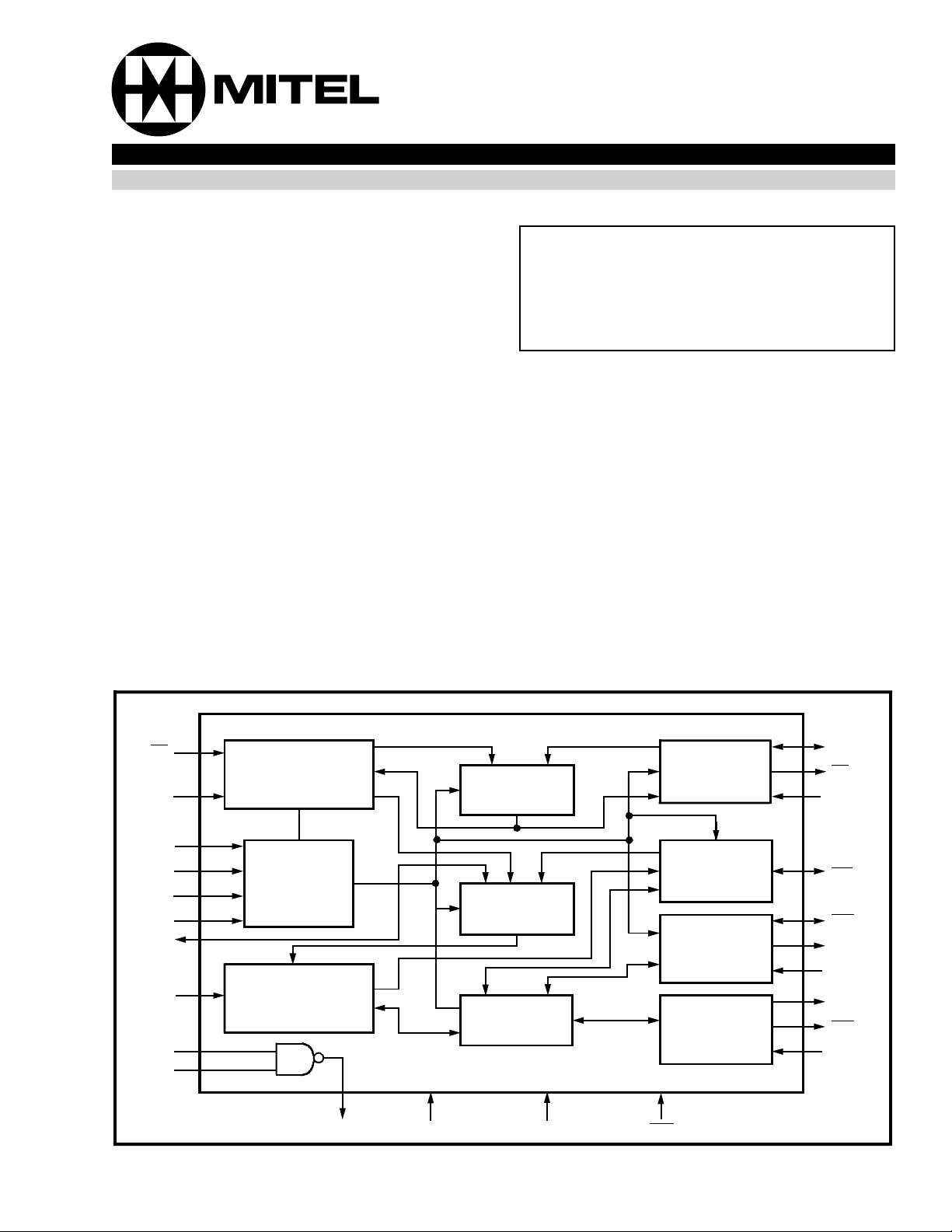
Figure 1 - Functional Block Diagram
3-27
27
Page 2
MT8940 ISO-CMOS
ENVC
MS0
C12i
MS1
F0i
F0b
MS2
C16i
ENC4o
C8Kb
C4o
VSS
1
2
3
4
5
6
7
8
9
10
11
12
24
23
22
21
20
19
18
17
16
15
14
13
VDD
RST
CV
CVb
Yo
Bi
Ai
MS3
ENC2o
C2o
C2o
C4b
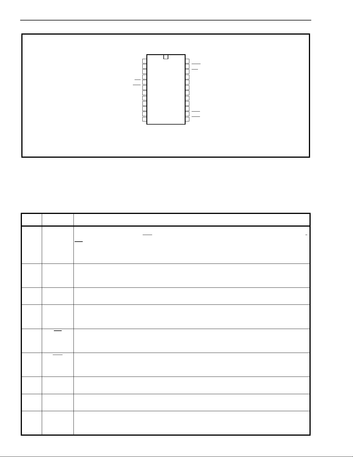
Figure 2 - Pin Connections
Pin Description
Pin # Name Description
1EN
Variable clock enable (TTL compatible input) - This input (pulled internally to VDD) directly
CV
controls the three states of CV
(pin 22) under all modes of operation. When HIGH, enables
CV and when LOW, put s it in high impedance condition. I t also controls the three states of
CVb signal (pin 21) if MS1 is LOW. When EN
is HIGH, the pin CVb is an output and when
CV
LOW, it is in high impedance state. However, if MS 1 is HIG H, CVb is always an input.
2MS0Mode select ‘0’ input (TTL compatible) - This input (pulled internally to V
) in conjunction
SS
with MS1 (pin 4) selects the major mode of operation for both DPLLs. (Refer to T ables 1 and
2).
3 C12i Clock 12.355 MHz i nput (T TL compa tibl e) - Master clock input at 12.355 MHz ±100ppm
for DPLL #1.
4MS1Mode select-1 input (TTL compatible) - This input (pulled internally to V
) in conjunction
SS
with MS0 (pin 2) selects the major mode of operation for both DPLLs. (Refer to T ables 1 and
2)
5F0i
Frame pu lse inpu t (TTL com pati ble) - This is the frame pulse input (pulled internally to
V
) at 8 kHz. The DPLL #1 locks to the falling edge of this input to generate T1 (1.544
DD
MHz) clock.
6F0b
Frame pu lse Bi directi on al (TT L comp atib le inp ut and Totem-pole outp ut) - Depending
on the minor mode selected for the DPLL #2, it provides the 8 kHz frame pulse output or acts
as an input (pulled internally to V
7MS2Mode select-2 input (TTL compatible) - This input (pulled internally to V
) to an external frame pulse.
DD
) in conjunction
DD
with MS3 (pin 17) selects the minor mode of operatio n for the DPLL #2. (Refer to Table 3. )
8 C16i Clock 16.388 MHz input (TTL compatible) - Master clock input at 16.388 MHz±32 ppm for
DPLL #2.
9EN
Enable 4.096 MHz cloc k (TTL co mpati bl e input) - This active high input (pulled inte rn ally
C4o
to V
) enables C4o (pin 11) output . When LOW, the output C4o is in high impedance
DD
condition.
3-28
Page 3
ISO-CMOS MT8940
Pin Description (continued)
Pin # Name Description
10 C8Kb Clock 8 kHz- Bidirectional (TTL com pati ble input and open drain output wi th 100K
internal resistor to V
locks during its NORMAL mode. When DPLL #2 is in SINGLE CLOCK mode, this pin outputs
an 8 kHz signal provided by DPLL #1, which is also connected internall y to DPLL #2.
11 C4o Clock 4.096 MHz (Three state output) - This is the inverse of the signal appearing on pin
13 (C4b
) at 4.096 MHz and has a rising edge in the frame pulse (F0b) window. The high
impedance state of this out put is cont rolled by EN
12 V
SS
13 C4b
Ground (0 Volt)
Clock 4.096 MH z- Bidirecti ona l (TTL comp atib le inpu t and Totem-pole output) - When
the mode select bit MS3 (pin 17) is HIGH, it provides the 4. 096 MHz clock output wit h the
falling edge in the frame pulse (F0b
) to an external clock at 4.096 MHz.
DD
14 C2o
internally to V
Clock 2.048 MHz (Three state output) - This is the divide by two output of C4b (pin 13) and
has a falling edge in the frame pulse (F0b
is controlled by EN
15 C2o Clock 2.048 MHz (Three state output) - This is the divide by two output of C4b
has a rising edge in the frame pulse (F0b
16 EN
controlled by EN
Enable 2.048 MHz cloc k (TTL co mpati bl e input) - This active high input (pulled inte rn ally
C2o
to V
) enables both C2o and C2o outputs (pins 14 and 15). When LOW, these outputs are
DD
C2o
in high impedance condition.
) - This is the 8 kHz input signal on the rising edge of which DPLL #2
DD
(pin 9).
C4o
) window. When pin 17 is LOW, C4b is an input (pulled
) window. The high impedance state of this output
(pin 16).
C2o
(pin 13) and
) window. The high impedance state of this output is
(pin 16).
17 MS3 Mode selec t 3 input (TTL com pati ble) - This input (pulled internally to V
) in conjunction
DD
with MS2 (pin 7) selects the minor mode of operation for DPLL #2. (Refer to Table 3.)
18,19 Ai, Bi Inputs A and B (TTL compatible) -These are the two inputs (pulled internally to V
20 Y
uncommitted NA ND gat e
Output Y (Totem pole output) - Output of the uncommitted NAND gate.
o
.
SS
21 CVb Variable clock Bidi recti on al (TTL com p atib le input and Totem-pole output) - When
acting as an output (MS1-LOW) during the NORMAL mode of DPLL #1, this pin provides the
1.544 MHz clock locked to the input frame pulse F0i
input (pulled internally to V
) to an external clock at 1.544 MHz or 2.048 MHz to provide the
DD
(pin 5). When MS1 is HIGH, it is an
internal signal at 8 kHz to DPLL #2.
22 CV
23 RST
Variable clock (Three state output) - This is the inverse output of the signal appearing on
pin 21, the high impedance state of which is control led EN
CV
(pin 1).
Reset (Schmitt trigger input) -This input (active LOW) e voke s reset condi tio n for the
device.
24 V
DD
VDD (+5V) Power supply.
) of the
3-29
Page 4
MT8940 ISO-CMOS
Functional Description
The MT8940 is a dual digital phase-locked loop
providing the timing and synchronization signals to
the interface circuits for T1 and CEPT (30+2)
Primary Multiplex Digital Transmission links. As
shown in Figure 1, it has two digital phase-locked
loops (DPLLs), associated output controls and the
mode selection logic circuits. The two DPLLs,
although similar in principle, operate independently
to provide T1 (1.544 MHz) and CEPT (2.048 MHz)
transmission clocks, and ST-BUS timing signals.
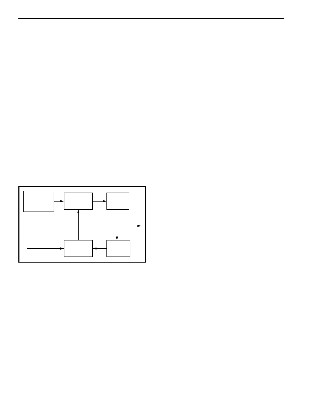
The principle of operation behind the two DPLLs is
shown in Figure 3. A master clock is divided down to
8 kHz where it is compared with the 8 kHz input, and
depending on the output of the phase comparison,
the master clock frequency is corrected. The
MT8940 achieves the frequency correction in both
directions by using the master clock at a slightly
higher frequency and dividing it unaltered or
stretching its period (at two discrete instants in a
frame) before the division depending on the phase
comparison output. When the input frequency is
Master Clock
(12.355 MHz/
16.388 MHz)
Frequency
Correction
÷8
Output
(1.544 MHz /
2.048 MHz)
The phase sampling is done once in a frame (8 kHz)
and the divisions are set at 8 and 193 for DPLL #1,
which locks on to the falling edge of the input at 8
kHz to generate T1 (1.544 MHz) clock. Although t he
phase sampling duration is the same for DPLL #2,
the divisions are set at 8 and 256 to provide the
CEPT/ST-BUS clock at 2.048 MHz synchronized to
the rising edge of the input signal (8 kHz). The
master clock source is specified to be at 12. 355 MHz
±100 ppm for DPLL #1 and 16.388 MHz ±32 ppm for
DPLL #2 over the entire temperature range of
operation.
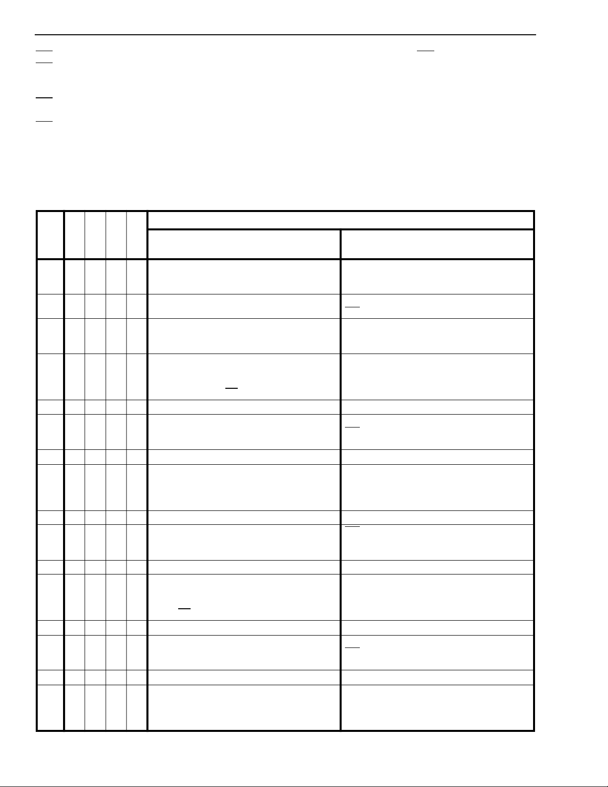
The inputs MS0 to MS3 are used to select the
operating mode of the MT8940, see Tables 1 to 4. All
the outputs are individually controlled to the high
impedance condition by their respective enable
controls. The uncommitted NAND gate is available
for use in applications involving MITEL’s
MT8976/MH89760 (T1 interfaces) and
MT8979/MH89790 (CEPT interfaces).
Modes of Operation
The operation of the MT8940 is categorized into
major and minor modes. The major modes are
defined for bot h DPLLs by the mode select pins MS0
and MS1. The minor modes are selected by MS2
and MS3, and are applicable only to DPLL #2. There
are no minor modes for DPLL #1.
Major m od es of th e D PLL #1
Input (8 kHz)
Phase
Comparison
÷193 /
÷256
Figure 3 - DPLL Principle
higher, the unchanged master clock is divided, thus
effectively speeding-up the locally generated clock
and eventually pulling it in synchronization with the
input. If the input frequency is lower than the divided
master clock, the period of the master clock is
stretched by half a cycle, at two discrete instants in a
phase sampling period. This introduces a total delay
of one master clock period over the sampling
duration, which is then divided to generate the local
signal synchronous with the input. Once the output is
phase-locked to the active edge of the input, the
circuit will maintain the locked condition as long as
the input frequency is within the lock-in range (±1.04
Hz) of the DPLLs. The lock-in range is wide enough
to meet the CCITT line rate specification (1.544
MHz±130ppm and 2.048 MHz ±50ppm) for the High
Capacity Terrestrial Digita l S ervice.
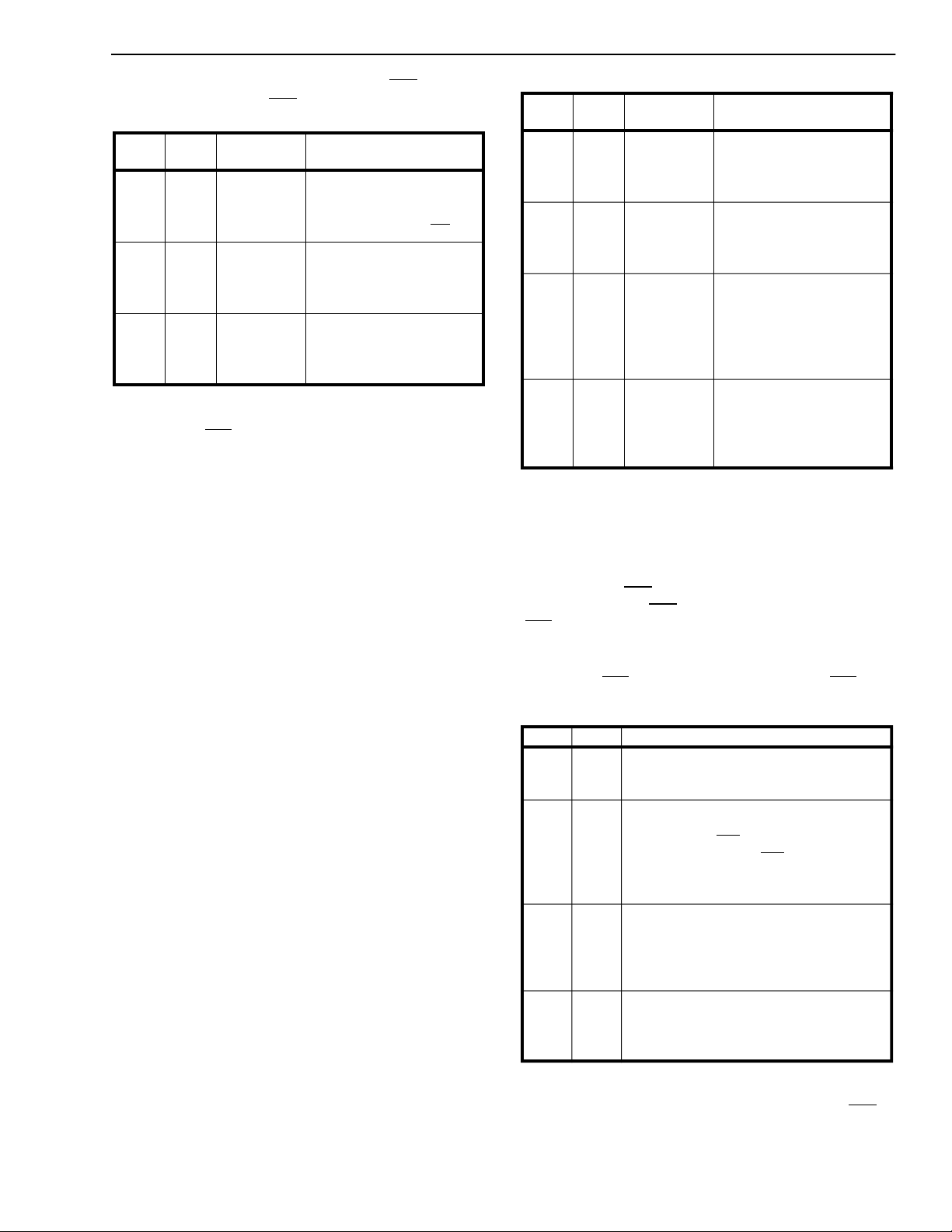
DPLL #1 can be operated in three major modes as
selected by MS0 and MS1 (Table 1). When MS1 is
LOW, it is in NORMAL mode, which provides a T1
(1.544 MHz) clock signal locked to the falling edge of
the input frame pulse F0i
(8 kHz). DPLL#1 requires a
master clock input of 12.355 MHz±100 ppm (C12i).
In the second and third major modes (MS1 is HIGH),
DPLL #1 is set to DIVIDE an external 1.544 MHz or
2.048 MHz signal applied at CVb (pin 21). The
division can be set by M S0 to be either 193 (LOW) or
256 (HIGH). In these modes, the 8 kHz output is
connected internally to DPLL #2, which operates in
SINGLE CLOCK mode.
Major m od es of th e D PLL #2
There are four major modes for DPLL #2 selectable
by MS0 and MS1, as s hown in Table 2. In all these
modes DPLL #2 provides the CEPT PCM 30 timing,
and the ST-BUS clock and framing signals.
In NORMAL mode, DPLL #2 provides the CEPT and
ST-BUS compatible timing signals locked to the
rising edge of the 8 kHz input signal (C8Kb). These
3-30
Page 5
signals are the 4.096 MHz (C4o and C4b) and the
2.048 MHz (C2o and C2o
MS0 MS1
X 0 NORMAL Provides the T1 (1.544
0 1 DIVIDE-1 DPLL #1 divides the CVb
1 1 DIVIDE-2 DPLL #1 divides the CVb
Note: X: i ndic at es d on ’t car e
Mode of
operatio n
) clocks, and the 8 kHz
Function
MHz) clock synchronized
to the falling edge of the
input frame pulse (F0i
input by 193. The divided
output is connected to
DPLL #2.
input by 256. The divided
output is connected to
DPLL #2.
).
Table 1. Major Modes of the DPLL #1
frame pulse (F0 b
), which are derived from the 16.388
MHz master clock. This mode can also provide the
ST-BUS timing and framing signals with the input
(C8Kb) tied HI GH and the master clock set at 16.384
MHz. The DPLL makes no correction in this
configuration and provides the timing signals
compatible to the ST-BUS format without any jitter.
In FREE-RUN mode, DPLL #2 generates CE PT and
ST-BUS timing and framing signals with no external
inputs except the master clock set at 16.388 MHz.
Since the master clock source is set at a higher
frequency than the nominal value, the DPLL makes
the necessary corrections to deliver the averaged
timing signals compatible to the ST-BUS format.
The operation of DPLL #2 in SINGLE CLOCK-1
mode is identical to SINGLE CLOCK-2 mode,
providing the CEPT and ST-BUS compatible timing
signals synchronized to the internal 8 kHz signal
obtained from DPLL#1 in DIVIDE mode. When
SINGLE CLOCK-1 mode is selected for DPLL #2, it
automatically selects the DIVIDE-1 mode for DPLL
#1, and thus, an external 1.544 MHz clock signal
applied at CVb (pin 21) is divided by DPLL #1 to
generate the internal signal at 8 kHz onto which
DPLL #2 locks. Similarly when SINGLE CLOCK-2
mode is selected, DPLL #1 is in DIVIDE-2 mode,
with an external signal of 2.048 MHz providing the
internal 8 kHz signal to DPLL #2. In both these
modes, this int ernal signal is available on C8Kb (pin
10) and DPLL #2 locks to its falling edge to provide
the CEPT and ST-BUS compatible timing signals.
This is in contrast to the Norm al mode where these
timing signals are synchronized with the rising edge
of the 8 kHz signal on C8Kb.
Minor modes of the DPLL #2
ISO-CMOS MT8940
MS0 MS1
0 0 NORMAL Provides ST-BUS/CEPT
1 0 FREE-RUN Provides ST-BUS timing
0 1 SINGLE
1 1 SINGLE
Tab le 2. M ajor M od es of th e DPLL #2
When MS3 is HIGH, DPLL #2 operates in any of the
major modes as selected by MS0 and MS1.
When MS3 is LOW, it overrides the major mode
selected and DPLL #2 accepts an external clock of
4.096 MHz on C4b
clocks (C2o and C2o
) compati ble with the ST-BUS form a t.
(F0b
The mode select bit MS2, controls the signal
direction of F0b
input for an external frame pulse at 8 kHz. This
MS2 MS3 Functional Description
1 1 Provides ST-BUS 4.096 MHz and 2.048
0 1 Provides ST-BUS 4.096 MHz & 2.048 MHz
0 0 Overrides the major mode selected and
1 0 Overrides the major mode selected and
Tab le 3. M inor Modes o f the DP LL #2
Mode of
operatio n
CLOCK-1
CLOCK-2
timing signals locked to the
rising edge of the 8kHz
input signal at C8Kb.
and framing signals with no
external inputs, except the
master clock.
Provides the CEPT/ STBUS compatible timing
signals locked to the falling
edge of the 8kHz internal
signal provided by DPLL
#1.
Provides CEPT/ST-BUS
timing signals locked to the
falling edge of the 8kHz
internal signal provided by
DPLL #1.
Function
(pin 13) to provide the 2.048 MHz
) and the 8 kHz frame pulse
(pin 6). When MS2 is LOW, F0b is an
MHz clocks and 8kHz frame pulse
depending on the major mode selected.
clocks depending on the major mode
selected while F0b
However , the input on F0b
the operation of DPLL #2 unless it is in
FREE-RUN mode.
accepts properly phase related external
4.096 MHz clock and 8 kHz frame pulse to
provide the ST-BUS compatible clock at
2.048MHz.
accepts a 4.096 MHz external clock to
provide the ST-BUS clock and f rame pulse
at 2.048 MHz and 8 kHz, respectively.
acts as an input.
has no ef fect on
The minor modes for DPLL #2 depends upon the
status of the mode select bits MS2 and MS3 (pins 7
and 17).
input is effective only if MS3 is also LOW and C4b
is
accepting a 4.096 MHz external clock, which has a
proper phase relationship with the external input on
3-31
Page 6
MT8940 ISO-CMOS
F0b (refer to Figure 15). Otherwise, the input on pin
will have no bearing on the operation of DPLL
F0b
#2, unless it is in FRE E-RUN mode as select ed by
MS0 and MS1. In FREE-RUN mode, the input on
F0b
is treated the same way as the C8Kb input in
NORMAL mode. The frequency of the input signal on
F0b
should be 16 kHz for DPLL #2 to provide the S TBUS compatible clocks at 4.096 MHz and 2.048
MHz.
M
O
MS0MS1MS2MS
D
E
#
0 0000
3
NORMAL MODE
DPLL #1 DPLL #2
1 0001NORMAL MODE
2 0010NORMAL MODE
NORMAL MODE:
3 0011
4 0100
Provides the T1 (1.544 MHz) clock
synchronized to the falling edge of the
input frame pulse (F0i
DIVIDE-1 MODE Same as mode ‘0’.
).
5 0101DIVIDE-1 MODE
6 0110
7 0111
8 1000
DIVIDE-1 MODE Same as mode 2.
DIVIDE-1 MODE:
Divides the CVb input by 193. The divided
output is connected to DPLL #2.
NORMAL MODE Same as mode ‘0’.
NORMAL MODE F0b is an input and DPLL #2 locks on to
9 1001
10 1010
11 1011
12 1100
NORMAL MODE Same as mode 2.
NORMAL MODE
Provides the T1 (1.544 MHz) clock
synchronized to the falling edge of input frame
pulse (F0i
DIVIDE-2 MODE Same as mode ‘0’.
DIVIDE-2 MODE SINGLE CLOCK-2 MODE:
).
13 1101
14 1110
15 1111
DIVIDE-2 MODE Same as mode 2.
DIVIDE-2 MODE:
Divides the CVb input by 256. The divided
output is connected to DPLL#2.
Tab le 4. S umm ary o f Mo des o f Oper atio n - DPLL #1 an d #2
When MS2 is HIGH, the F0b
pin provides the STBUS frame pulse output locked to the 8kHz internal
or external signal as determined by the other mode
select pins MS0, MS1 and MS 3 .
Table 4 summarizes t he modes of the two DP LLs. It
should be noted that each of the major modes
selected for DPLL #2 can have any of the minor
modes, although some of the combinations are
functionally similar. The required operation of both
DPLL#1 and DPLL#2 must be considered when
determining MS0-MS3.
Operating Mo des
Properly phase related External 4.096 MHz
clock and 8 kHz frame pulse provide the STBUS clock at 2.048 MHz.
NORMAL MODE
F0b
is an input but has no function in this mode.
External 4.096 MHz provides the ST-BUS clock
and Frame Pulse at 2.048 MHz and 8 kHz,
respectively.
NORMAL MODE:
Provides the CEPT/ST-BUS compatible timing
signals locked to the 8 kHz input signal (C8Kb).
SINGLE CLOCK-1 MODE
F0b is an input, but has no function in this
mode.
SINGLE CLOCK-1 MODE:
Provides the CEPT/ST-BUS compatible timing
signals locked to the 8 kHz internal signal
provided by DPLL # 1.
it only if it is at 16 kHz to provide the ST-BUS
control signals.
FREE-RUN MODE:
Provides the ST-BUS timing signals with no
external inputs except the master clock.
F0b
is an input, but has no function in this
mode.
SINGLE CLOCK-2 MODE:
Provides the CEPT/ST-BUS compatible timing
signals locked to the 8 kHz internal signal
provided by DPLL # 1.
3-32
Page 7
ISO-CMOS MT8940
Applications
The following figures illustrate how the M T8940 can
be used in a minimum component count approach to
providing the timing and synchronization signals for
the Mitel T1 and CEPT interfaces, and the ST-BUS.
The hardware selectable modes and the
independent control over each PLL adds flexibility to
the interface circuits. It can be easily reconfigured to
provide the timing and control signals for both at the
master and slave ends of the link.
Synchronization and Timing Signals for the T1
Transmission L ink
Figures 4 and 5 show examples of how to generate
the timing signals for the master and slave ends of a
T1 link.
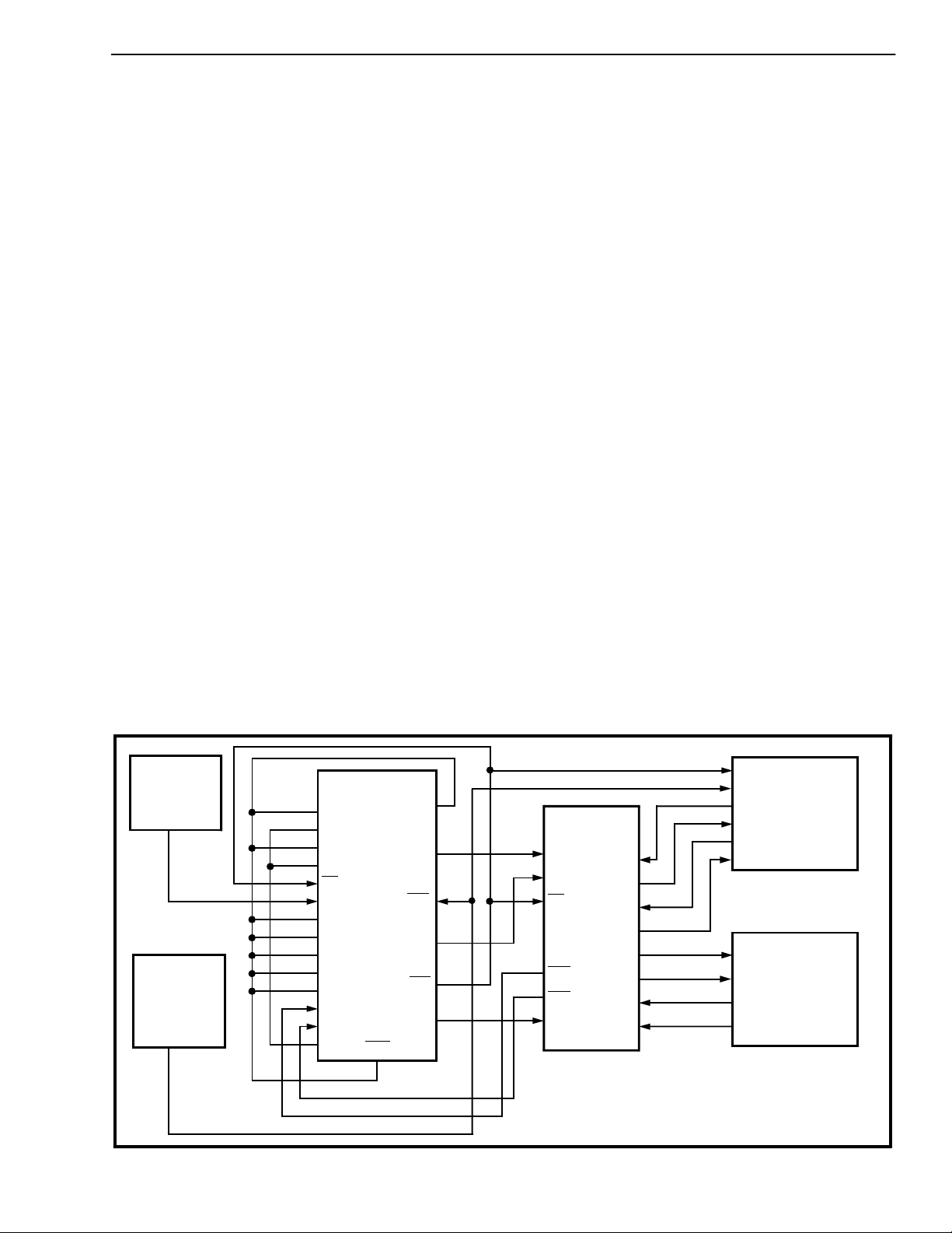
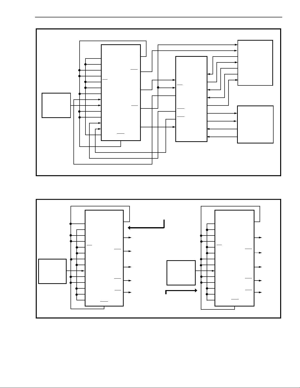
At the master end of the link (Figure 4), DPLL #2 is
the source of the ST-BUS signals derived from the
4.096 MHz system clock. The frame pulse output is
looped back to DPLL #1 (in NORMAL mode), which
locks to it to generate the T1 line clock. The timing
relationship between the 1.544 MHz T1 clock and
the 2.048 MHz ST-BUS clock meets the
requirements of the MH89760/760B. The crystal
clock at 12.355 MHz is used by DPLL #1 to generate
the 1.544 MHz clock, while DPLL #2 uses the 4.096
MHz system clock to provide the ST-BUS timing
signals. The ST-BUS signals can also be obtained
from DPLL #2 in FREE-RUN mode, using a crystal
clock at 16.388 MHz instead of 4.096 MHz system
clock. The uncommitted NAND gate converts the
received signals, RxA and RxB of the MH89760 to a
single Return to Zero (RZ) input for the clock
extraction circuits of the MH89760. This is not
required for the MH 89760B. The generated ST-BUS
signals can be used to synchronize the system and
the switching equipment at the master end.
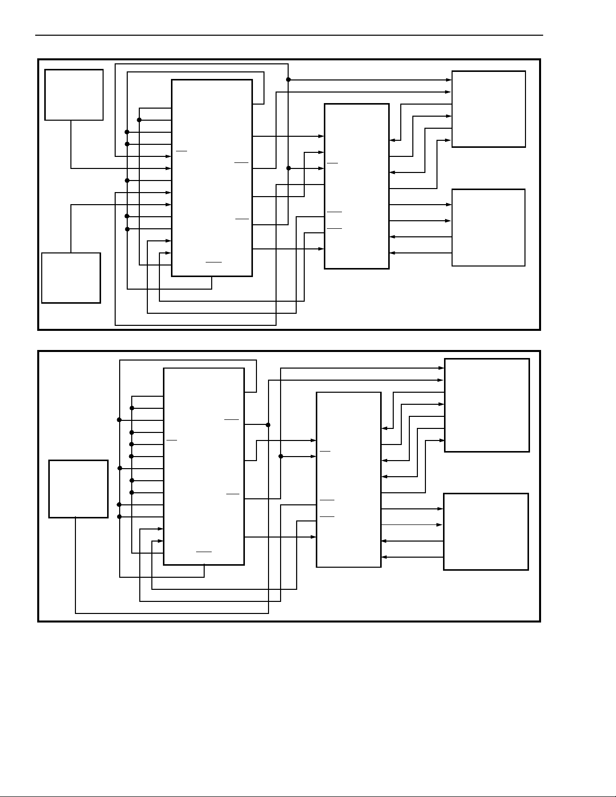
At the slave end of the link (Figure 5) both the DPLLs
are in NORMAL mode with DPLL #2 providing the
ST-BUS timing signals locked to the 8 kHz frame
pulse (E8Ko) extracted from the received signal on
the T1 line. The regenerated fr ame pulse is looped
back to DPLL #1 to provide the T1 line clock as at
the master end. The 12.355 MHz and 16.388 MHz
crystal clock sources are necessary for DPLL #1 and
#2.
Synchronization and Timing Signals for the
CEPT Transmissi o n L i n k
The MT8940 can be used to provide the timing and
synchronization signals for the MH89790/790B,
MITEL’s CEPT(30+2) digital trunk interface hybrid.
Since the operational frequencies of the ST-BUS and
the CEPT primary multiplex digital trunk are same,
only DPLL #2 is required to achieve synchronization
between the two
.
Figures 6 and 7 show how the MT8940 can be used
to synchronize the ST-BUS and the CEPT
transmission link at the master and slave ends,
respectively.
Crystal Clock
(12.355 MHz
±100 ppm)
4.096 MHz
System Clock
(ST-BUS
compatible)
MT8980/81
ST-BUS
SWITCH
T1
LINK
(1.544 Mbps)
MS0
MS1
MS2
MS3
F0i
C12i
EN
CV
C8Kb
C16i
EN
C4o
EN
C2o
Ai
Bi
V
SS
MT8940
RST
V
DD
CV
C4b
C2o
F0b
Y
MH89760
C1.5i
C2i
F0i
RxA
RxB
o
RxD
DPLL #1 - NORMAL (MS0 = X; MS1 = 0)
DPLL #2 - OVERRIDE THE MAJOR MODES (MS2 = 1; MS3 = 0)
DSTi
DSTo
CSTi
CSTo
TxT
TRANSMIT
TxR
RxT
RxR
MODE OF OPERATION FOR THE MT8940
RECEIVE
Figure 4 - Synchronization at the Master End of the T1 Transmission Link
3-33
Page 8
MT8940 ISO-CMOS
Crystal Clock
(12.355 MHz
± 100 ppm)
Crystal Clock
(16.388 MHz
± 32 ppm)
4.096 MHz
System Clock
(ST-BUS
Compatible)
MT8980/81
ST-BUS
SWITCH
(1.544 Mbps)
MS0
MS1
MS2
MS3
F0i
C12i
EN
CV
C8Kb
C16i
EN
C4o
EN
C2o
Ai
Bi
V
SS
MT8940
RST
V
DD
CV
C4b
C2o
F0b
Y
MH89760
C1.5i
C2i
F0i
RxA
RxB
o
RxD
DPLL #1 - NORMAL (MS1=0)
DPLL #2 - NORMAL (MS0=0; MS1=0; MS2=1; MS3=1)
DSTi
DSTo
CSTi
CSTo
TxT
TxR
RxT
RxR
Mode of Operation for the MT8940
TRANSMIT
RECEIVE
Figure 5 - Syn c hroniz ation at the S lave E nd of th e T1 Transmiss ion Lin k
MT8980/81
MT8940
V
MS0
MS1
MS2
MS3
F0i
C12i
EN
CV
C8Kb
C16i
EN
C4o
EN
C2o
Ai
Bi
V
SS
RST
DD
C4b
C2o
F0b
Y
MH89790
DSTi
C2i
F0i
RxA
RxB
o
RxD
DSTo
CSTi0
CSTi1
CSTo
OUTA
OUTB
RxT
RxR
TRANSMIT
RECEIVE
ST-BUS
SWITCH
PRIMARY
MULTIPLEX
DIGITAL
T1
LINK
CEPT
LINK
Figure 6 - Synchronization at the Master End of the CEPT Digital Transmission Link
Genera ti on o f S T-BUS Timi ng S ig nal s
The MT8940 can source the properly formatted STBUS timing and control signals with no external
inputs except the crystal clock. This can be used as
the standard timing source for ST-BUS systems or
any other system with similar clock requirements.
Figure 8 shows two such applications using only
DPLL #2. In one case, the MT8940 is in FREE-RUN
3-34
DPLL #1 - NOT USE D
DPLL #2 - OVERRIDE MAJOR MODES (MS0=X; MS1=X
MS2=1; MS3=0)
Mode of Operation for the MT8940
mode with an oscillator input of 16.388 MHz. This
forces the DPLL to correct at a rate of 4 kHz to
maintain the ST-BUS clocks, which therefore, will be
jittered. In the other case, the oscillator input is
16.384 MHz (exactly eight times the output
frequency) and DPLL #2 operates in NORMAL mode
with C8Kb input tied HIGH. Since no corrections are
necessary, the output is free from jitter. DPLL #1 is
completely free in both cases and available for any
other purpose.
Page 9
ISO-CMOS MT8940
Crystal Clock
(16.388 MHz
± 32 ppm)
Figure 7 - Sy nchr onizat ion at th e Slav e End o f the CEP T Dig ital Transmission Link
MS0
MS1
MS2
MS3
F0i
C12i
EN
CV
C8Kb
C16i
EN
C4o
EN
C2o
Ai
Bi
V
SS
MT8940
RST
V
C4b
C2o
F0b
DD
Y
MT8980/81
MH89790
ST-BUS
SWITCH
C2i
F0i
DSTi
DSTo
CSTi0
CSTi1
CSTo
RxA
RxB
o
RxD
OUTA
OUTB
RxT
RxR
TRANSMIT
RECEIVE
CEPT
PRIMARY
MULTIPLEX
DIGITAL
LINK
Mode of Operation for the MT8940
DPLL #1 - NOT USED
DPLL #2 - NORMAL (MS0=0; MS1=0; MS2=1; MS3=1)
Crystal Clock
(16.388 MHz
± 32 ppm)
DPLL #1 - NOT USED
DPLL #2 - NORMAL MODE
(MS0=0; MS1=0; MS2=1;
MS3=1)
MS0
MT8940
V
DD
MS1
MS2
MS3
F0i
C12i
EN
CV
C8Kb
C16i
EN
C4o
EN
C2o
C4o
C4b
C2o
C2o
ST-BUS
TIMING
SIGNALS
Crystal Clock
(16.388 MHz
± 32 ppm)
Ai
RST
F0b
DPLL #1 - NOT USED
DPLL #2 - NORMAL MODE
(MS0=0; MS1=0;
MS2=1; MS3=1)
Bi
V
SS
Figure 8 - Generation of the ST-BUS Timing Signals
MS0
MS1
MS2
MS3
F0i
C12i
EN
CV
C8Kb
C16i
EN
C4o
EN
C2o
Ai
Bi
V
SS
MT8940
RST
V
DD
C4o
C4b
C2o
C2o
F0b
ST-BUS
TIMING
SIGNALS
3-35
Page 10
MT8940 ISO-CMOS
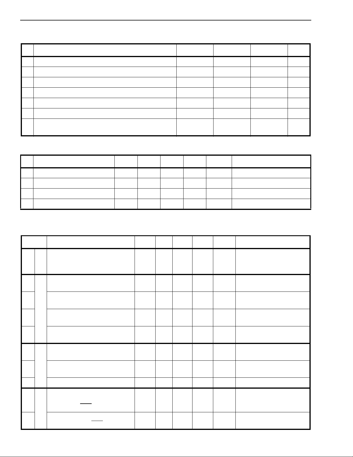
Absolute Maximum Rating s*- Voltages are with respect to ground (V
) unless otherwise stated.
SS
Parameter Symbol Min Max Units
1 Supply Voltage V
2 Voltage on any pin V
3 Input/Outp ut Diode Current I
4 Outpu t Source or Sink Current I
5 DC Supply or Ground Current I
6 Storage Temperature T
7 Package Power Dissipati on Ceramic DIP
LCC
* Exceeding these values ma y cause perm anen t dama ge. Functi onal operati on und er these cond ition s is not implied.
DD
I
IK/OK
O
DD/ISS
ST
P
D
P
D
Recommended Operating Conditions - Voltages are with respect to ground (V
Characteristics Sym Min Typ
1 Suppl y Voltage V
2 Input HIGH Voltage V
3 Input LOW Voltage V
4 Op erati ng Temperature T
‡ Typical figures are at 25°C and are for design aid only: not guarantee d and not subje ct to producti on testing.
DD
IH
IL
A
4.75 5.0 5.25 V
2.4 V
V
SS
-40 25 85
‡
Max Units Test Con di tio ns
DD
0.4 V For 400 mV noise margin
-0.3 7.0 V
VSS-0.5 VDD+0.5 V
-65 150
) unless otherwise stated.
SS
V For 400 mV noise margin
o
C
±10 mA
±25 mA
±50 mA
o
1200
600
mW
mW
C
DC Electrical Characteristics - Voltages are with respect to ground (V
V
=5.0 V±5%; VSS=0V; TA=-40 to 85°C.
DD
Characteristics Sym Min Typ‡Max Units Test Conditions
S
U
1
Supply Current
P
2
Input HIGH vol tage (Fo r all the
inputs except pin 23)
3 Positive-going threshold
voltage (For pin 23)
I
N
4 Input LOW voltage (For all the
inputs except pin 23)
5 Negative-going threshold
voltage (For pin 23)
6
7 Output current LOW (For all the
Output current HIGH (For all
the outputs except pin 10)
O
U
T
outputs e xcept pin 10 )
8 Output current LOW (pin 1 0) I
9 Leakage current on bidirect-
ional pins and all inputs except
C12i, C16 i, RST
I
DD
I
DDS
V
V
V
V
I
OH
I
OL
OL
I
IZ/OZ
2.0 V
IH
2.8 V
+
IL
-
-9.5 mA VOH=2.4 V
4.5 mA VOL=0.4 V
2.0 mA
815
) unless otherwise stated .
SS
mA
100
Under clocked condition, with the
inputs tied to the same supply rail
as the corresponding pull-up /
down resistors.
0.8 V
1.5 V
VOL
±150 µAV
I/O
=
=0.4 V
V
SS
or V
DD
10 L eakage current on all output s
and C12i, C16i, RST
‡ Typical figures are at 25°C and are for design aid only: not guarantee d and not subje ct to producti on testing.
3-36
inputs
I
IZ/OZ
±1 ±10 µAV
I/O=VSS
or V
DD
Page 11
ISO-CMOS MT8940
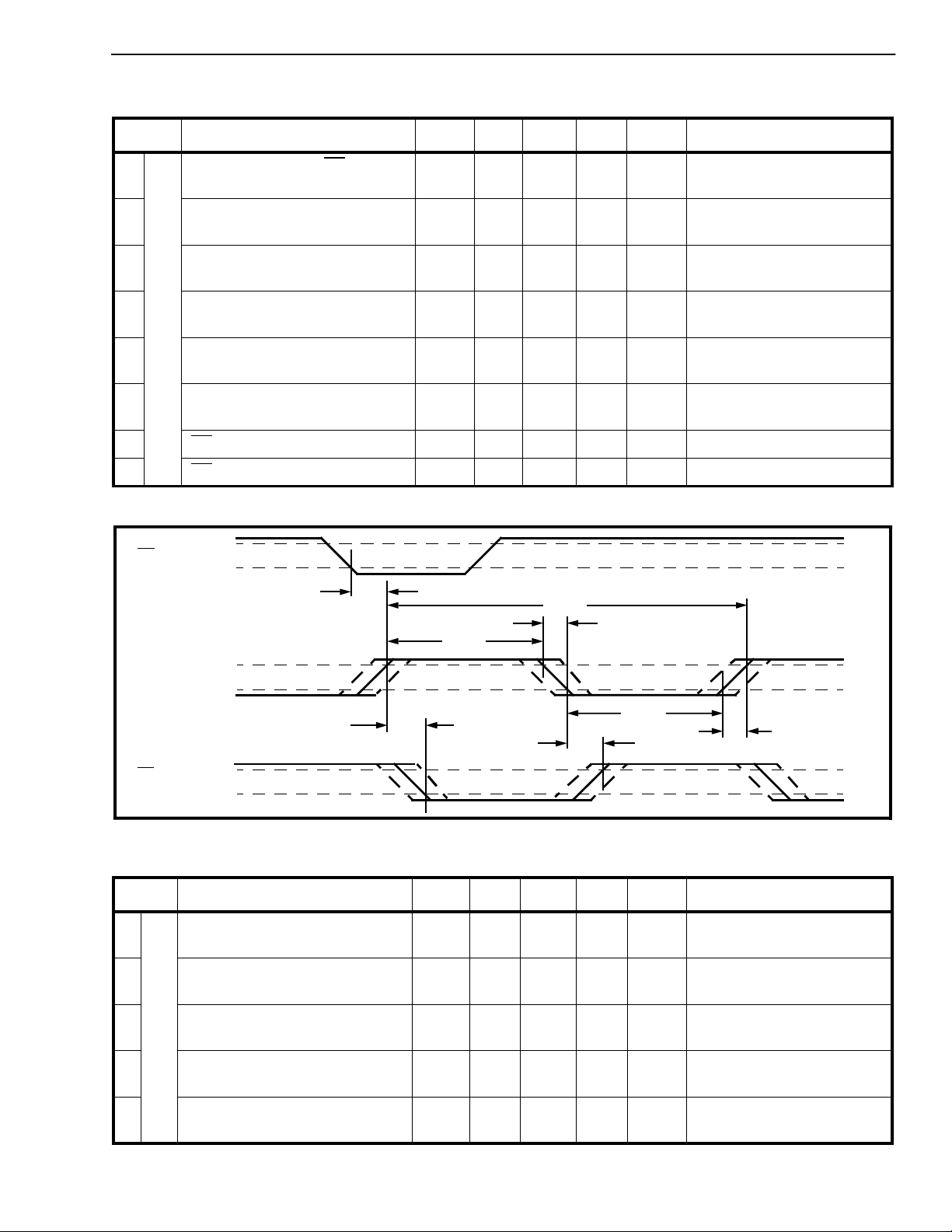
AC Electrical Characteristics† - V oltages are with respect to ground (V
Characteristics Sym Min Typ
1
Frame pulse input (F0i
) to CVb
output (1.544 MHz) delay
2 CVb output (1.544 MHz) rise
time
3 CVb output (1.544 MHz) fal l
D
time
t
F15H
t
r1.5
t
f1.5
-40 75 ns
‡
10 15 ns Test load circuit 1 (Fig. 17).
12 15 ns Test load circuit 1 (Fig. 17).
) unless otherwise stated. (Ref. Figure 9)
SS
Max Units Test Conditions
P
4 CVb output (1.544 MHz) clock
L
period
L
5 CVb output (1.544 MHz) clock
#1
width (HIGH)
6 CVb output (1.544 MHz) clock
width (LOW)
7CV
8CV
† Timing is over recommended temperature & power supply voltages.
‡ Typical figures are at 25°C and are for design aid only: not guarantee d and not subje ct to producti on testing.
F0i
CVb
CV
delay (HIGH to LOW) t
delay (LOW to HIGH) t
V
IH
V
IL
t
F15H
V
OH
V
OL
t
15HL
V
OH
V
OL
t
P15
t
W15H
t
W15L
15HL
15LH
648 690 ns
320 386 ns
314 327 ns
530ns
-12 10 ns
t
P15
t
W15H
t
15LH
t
f1.5
t
W15L
t
r1.5
Figure 9 - Timing Information for DPLL #1 in NORMAL Mode
AC Electrical Characteristics† - Voltages are with respect to ground (V
Characteristics Sym Min Typ
1
2 C8Kb output (8 kHz) delay
3 C8Kb output duty c ycle 66
C8Kb output (8kHz) delay
(HIGH to HIGH)
D
(LOW to LOW)
P
L
t
C8HH
t
C8LL
L
4 Inverted clock output delay
#1
(HIGH to LOW)
5 Inverted clock output delay
(LOW to HIGH)
† Timing is over recommended temperature & power supply voltages.
‡ Typical figures are at 25°C and are for design aid only: not guarantee d and not subje ct to producti on testing.
t
ICHL
t
ICLH
‡
50 1 30 ns Test load circuit 2 (Fig. 17).
50
40 75 ns
35 60 ns
) unless otherwise stated. (Ref. Figure 10)
SS
Max Uni ts Test Conditions
130 ns Test load circuit 2 (Fig. 17).
%
In Divide -1 Mode
%
In Divide - 2 Mode
3-37
Page 12
MT8940 ISO-CMOS
V
CVb
IH
V
IL
CV
C8Kb
F0b
t
ICHL
V
OH
V
OL
t
C8HH
V
OH
V
OL
t
ICLH
t
C8LL
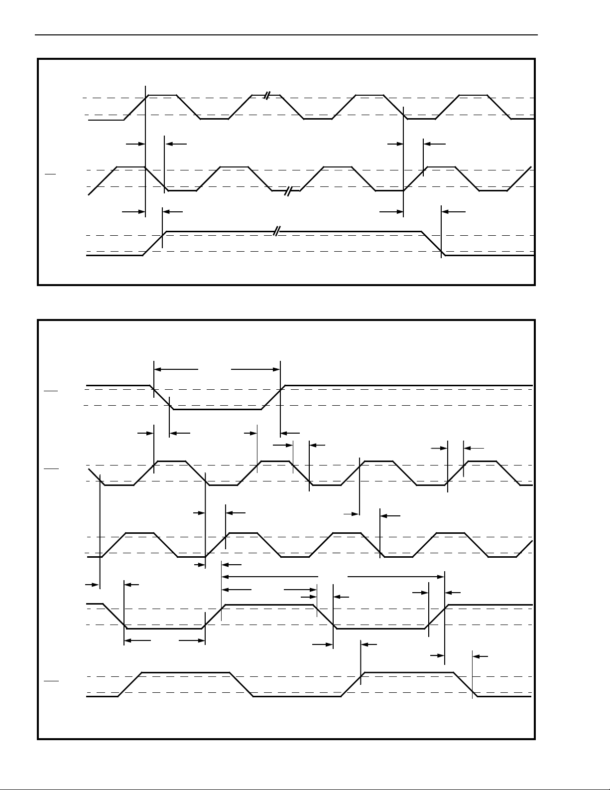
Figure 10 - DPLL #1 in DIVIDE Mode
t
WFP
V
OH
V
OL
C4b
C4o
C2o
C2o
t
FPL
V
OH
V
OL
V
OH
V
OL
t
V
OH
V
OL
V
OH
V
OL
42HL
t
W2oL
t
42LH
t
FPH
t
4oLH
t
W2oH
t
2oLH
t
4oHL
t
P2o
t
fC4
t
fC2
t
rC4
t
rC2
t
2oHL
3-38
Figure 11 - Timing Information on DPLL #2 Outputs
Page 13
ISO-CMOS MT8940
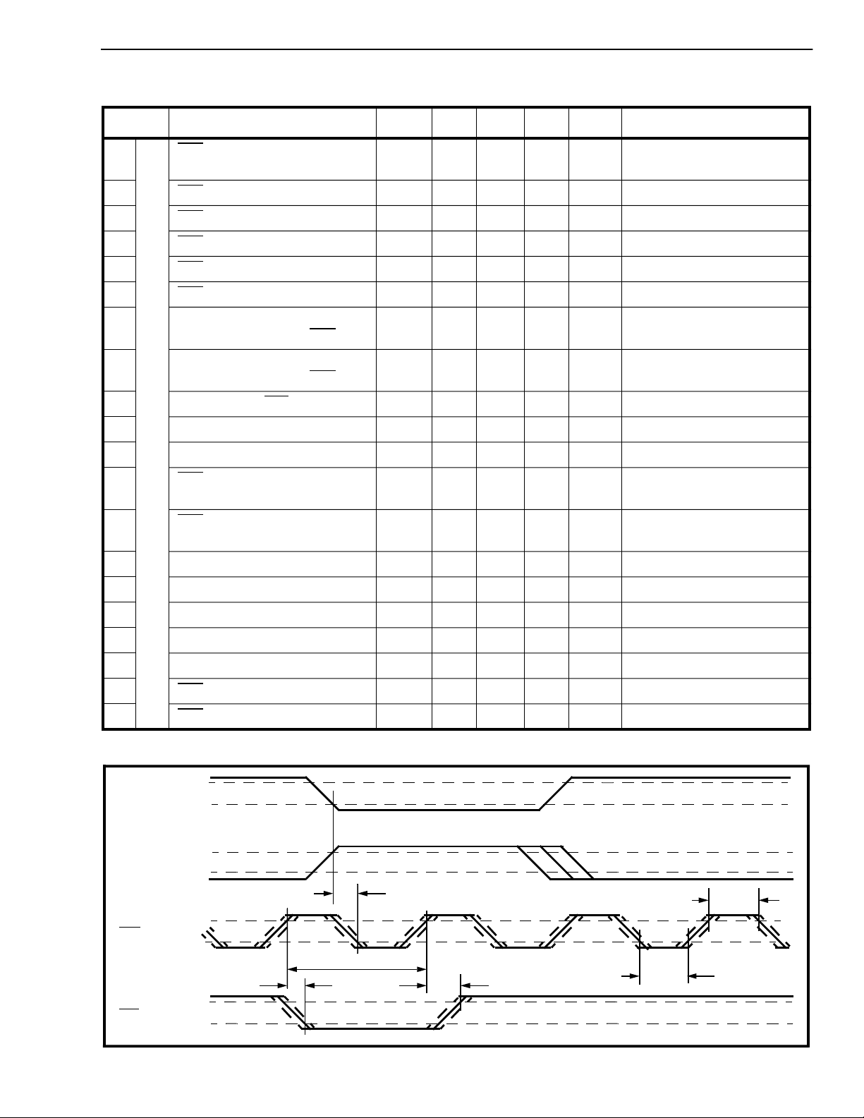
AC Electrical Characteristics
†
-Voltages are with respect to ground (V
Characteristics S ym Min Typ
1
output delay (HIGH to
C4b
LOW) from C8Kb input/output
2C4b
3C4b
4C4b
5C4b
6C4b
output clock period t
output clock width (HI G H) t
output clock width (LOW) t
output clock rise tim e t
clock output fall time t
7 Frame pulse output delay
(HIGH to LOW) from C4b
8 Frame pulse output delay
(LOW to HIGH) from C4b
D
9 Frame pulse (F0b
P
L
10 C4o delay - LOW to HIGH t
) width t
L
11 C4o delay - HIGH to LOW t
#2
12 C4b
to C2o del ay (LOW to
HIGH)
t
84H
P4o
W4oH
W4oL
rC4
fC4
t
FPL
t
FPH
WFP
4oLH
4oHL
t
42LH
) unless otherwise stated.(Ref. Figures 11&12)
SS
‡
Max Units Test Conditions
-25 75 ns
Test load circuit 2 (Fig. 17)
on C8Kb.
240 282 ns Test load circuit 1 (Fig. 17).
123 165 ns
110 123 ns
10 ns Test loa d circuit 1 (Fig. 17).
10 ns Test loa d circuit 1 (Fig. 17).
50 ns
40 ns
Test load circuit 1 (Fig. 17).
Test load circuit 1 (Fig. 17).
200 245 ns
45 ns
45 ns
-10 +10 ns
13 C4b
14 C2o clock period t
15 C2o clock width (HIGH) t
16 C2o clock width (LOW) t
17 C2o clock rise time t
18 C2o clock fall time t
19 C2o
20 C2o
† Timing is over recommended temperature & power supply voltages.
‡ Typical figures are at 25°C and are for design aid only: not guarantee d and not subje ct to producti on testing.
C8Kb
as
Output
C8Kb
as
Input
C4b
F0b
to C2o delay (HIGH to
LOW)
delay - LOW to HIGH t
delay - HIGH to LOW t
V
OH
V
OL
V
IH
V
IL
V
OH
V
OL
t
V
OH
V
OL
FPL
t
P4o
t
42HL
P2o
W2oH
W2oL
rC2
fC2
2oLH
2oHL
t
84H
20 ns
486 523 ns Test load circuit 1 (Fig. 10).
244 291 ns
233 244 ns
10 ns Test loa d circuit 1 (Fig. 10).
10 ns Test loa d circuit 1 (Fig. 10).
20 ns
-5 30 ns
t
t
FPH
W4oL
t
W4oH
Figure 12 - ST-BUS Timings from DPLL #2 a nd C8Kb Input/Output
3-39
Page 14
MT8940 ISO-CMOS
AC Electrical Characteristics
Characteristics Sym Min Typ
1CV
2CV
† Timing is over recommended temperature & power supply voltages.
‡ Typical figures are at 25°C and are for design aid only: not guarantee d and not subje ct to producti on testing.
F0b
C2o
CV
CVb
/CVb (1.544 MHz) Setup time t
/CVb (1.544 MHz) Hold time t
V
OH
V
OL
V
OH
V
OL
V
OH
V
OL
V
OH
V
OL
†
Voltages are with respect to ground (V
-
S15
H15
20 CYCLES
25 ns
110 ns
t
S15
t
S15
) unless otherwise stated. (Ref. Figure 13)
SS
‡
Max Units Test Conditions
Boundary between ST-BUS channel 2 bit 4 and
channel 2 bi t 3
t
H15
t
H15
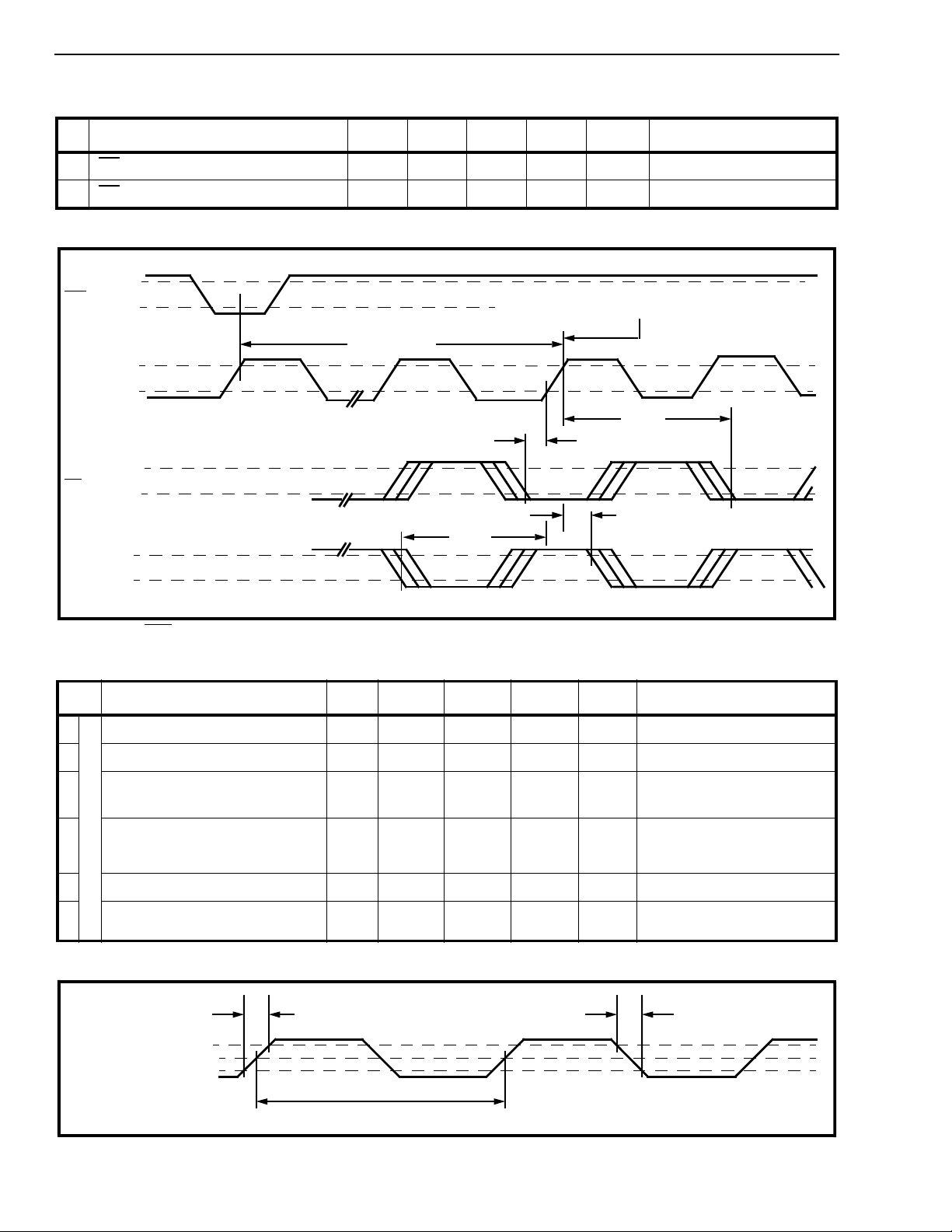
Figur e 13 - F0b from DPLL #2 is Looped Back as Input to DPLL #1 (T1 Line synchr onized to ST-BUS)
AC Electrical Characteristics† - Voltages are with respect to ground (V
Characteristi cs Sym Min Typ
1
Master clocks input rise time t
2 Master clocks input fall ti me t
C
3 Master clock period
L
(12.355MHz)
t
O
4
Master clock period
C
(16.388MHz)
K
t
r
f
80.930 80 .938 80.946 ns
P12
61.018 61 .020 61.022 ns
P16
‡
) unless otherwise stated. (Ref. Figu re 14)
SS
Max Units Test Con di tio ns
10 ns
10 ns
For DPLL #1, while oper ating to
provide the T1 clock signal.
For DPLL #2, while oper ating to
provide the CEPT and ST-BUS
timing signals.
S
5 Duty Cycle of m aster clocks 45 50 55 %
6 Lock-in Range (For each PLL)
† Timing is over recommended temperature & power supply voltages
‡ Typical figures are at 25°C and are for design aid only: not guarantee d and not subje ct to producti on testing.
t
r
Master clock
inputs
2.4 V
1.5 V
0.4 V
-1.5 +1.04 Hz
t
or t
P12
P16
With the Master clocks as shown
above.
t
f
3-40
Figure 14 - Master Clock Inputs
Page 15
ISO-CMOS MT8940
AC Electrical Characteristics† - Voltages are with respect to ground (V
t
‡
P4o
Characteristi cs Sym Min Typ
1F0b
2C4b
3 Frame pulse (F0b
4 Frame pulse (F0b
† Timing is over recommended temperature & power supply voltages
‡ Typical figures are at 25°C and are for design aid only: not guarantee d and not subje ct to producti on testing.
input pulse width (LOW) t
input clock period t
) setup time t
) hold time t
V
IH
F0b
V
IL
V
IH
C4b
V
IL
WFP
P4o
FS
FH
t
FS
40 ns
.080 50 µs
25 ns
5ns
t
WFP
t
FH
) unless otherwise stated. (Ref. Figure 15)
SS
Max Units Test Conditions
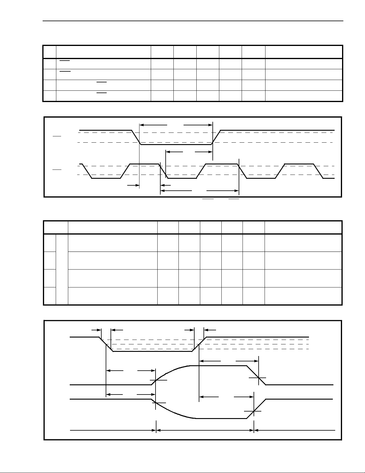
Figure 15 - Ex terna l Inputs on C4b and F0b fo r the DPL L #2
AC Electrical Characteristics† - Voltages are with respect to ground (V
Characteristics Sym Min Typ
1
Delay from Enable to Output
(HIGH to THREE STATE)
t
PHZ
‡
15 65 ns Test load circuit 3 (Fig.17)
) unless otherwise stated. (Ref. Figure 16)
SS
Max Units Tes t Co ndi tions
O
2 Delay from Enable to Outpu t
U
(LOW to THREE STATE)
T
P
3 Delay from Enable to Outpu t
U
(THREE STATE to HIGH)
t
PLZ
t
PZH
10 55 ns Test load circuit 3 (Fig.17)
40 ns Test load circuit 3 (Fig.17)
T
4 Delay from Enable to Outpu t
(THREE STATE to LOW)
† Timing is over recommended temperature & power supply voltages
‡ Typical figures are at 25°C and are for design aid only: not guarantee d and not subje ct to producti on testing.
6 ns t
t
PLZ
t
PHZ
Enable
Input
Output
LOW to
OFF
Output
HIGH
to OFF
t
f
Outputs
Enabled
t
PZL
10%
90%
r
Outputs
Disabled
50 ns Test load circuit 3 (Fig.17)
6 ns
t
PZL
1.3 V
t
PZH
1.3 V
Outputs
Enabled
3.0 V
2.7 V
1.3 V
0.3 V
Figure 16 - Three Sta te Outputs and Enable Tim ings
3-41
Page 16
MT8940 ISO-CMOS
AC Electrical Characteristics† - Uncommitted NAND Gate
Voltages are with respect to ground ( VSS) unless otherwise stated.
Characteristics Sym Min Typ
‡
Max Units Test Conditions
1 Propagation delay (LOW to
HIGH), input Ai or Bi to output
2 Propagation delay (HIGH to
LOW), input Ai or Bi to output
† Timing is over recommended temperature & power supply voltages.
‡ Typical figures are at 25°C and are for design aid only: not guarantee d and not subje ct to producti on testing.
From
output
under test
C
=50pF
L
Test load circuit- 1
Test
point
From
output
under test
C
t
PLH
t
PHL
V
DD
RL=1kΩ
Test
point
=50pF
L
Test load circuit- 2 Test load circuit- 3
25 40 ns Test load circuit 1 (Fig. 17)
20 40 ns Test load circuit 1 (Fig. 17)
Test
RL=1kΩ
From
output
under test
point
C
L
=50pF
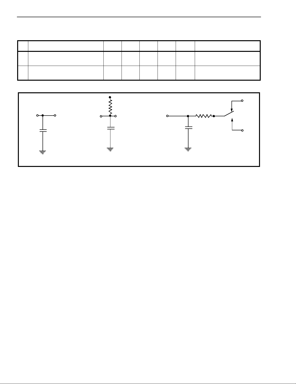
Figure 17 - Test Load Circuits
V
DD
A
B
S
1
V
SS
Note: S
when measuring t
and tPZ and in position B
when measuring t
t
PZH
is in position A
1
PLZ
PHZ
and
3-42
 Loading...