

Page 1

ISO-CMOS
MT8808
8 x 8 Analog Switch Array
Features
• Internal cont rol lat ches and add ress d eco der
• Short set-up and hold times
• Wide ope rating v oltag e: 4. 5V to 13.2V
• 12Vpp anal og s ignal capabi lity
•R
• ∆R
65Ω max. @ VDD=12V, 25°C
ON
≤ 10Ω @ VDD=12V, 25°C
ON
• Full CMOS switch for low distortion
• Minimum f eedthr oug h and c ros stal k
• Separate ana lo g and di gital re ferenc e supp lies
• Low power consumption ISO-CMOS technology
Applications
• Key systems
• PBX systems
• Mobile rad io
• Test equipment /instru men tatio n
• Analo g/ di gita l m ult ip le xers
• Audio/Video switching
ISSUE 2 November 1988
Ordering Information
MT8808AC 28 Pin Ce r am i c D IP
MT8808AE 28 Pin Pla stic D IP
MT8808AP 28 Pin PL C C
-40° to 85°C
Description
The Mitel MT8808 is fabricated in MITEL’s ISOCMOS technology providing low power dissipation
and high reliability. The device contains a 8 x 8 array
of crosspoint switches along with a 6 to 64 line
decoder and latch circuits. Any one of the 64
switches can be addressed by selecting the
appropriate six address bits. The selected switch can
be turned on or off by applying a logical one or zero
to the DATA input. V
the digital inputs. The range of the analog signal
is from V
to VEE.
DD
is the ground reference of
SS
AX0
AX1
AX2
AY0
AY1
AY2
STROBE DATA RESET VDD VEE VSS
11
8 x 8
6 to 64
Decoder
Latches
Switch
Array
6464
• • • • • • • • • • • • • • • • • • •
Yi I/O (i=0-7)
Figure 1 - Functional Block Diagram
• • • • • • • • • • • • • • • •
Xi I/O
(i=0-7)
3-15
Page 2

MT8808 ISO-CMOS
X0
X2
X4
X6
Y7
Y6
Y5
Y4
1
2
3
4
5
6
7
8
9
10
11
12
13
14
AY2
STROBE
VEE
DATA
VSS
RESET
28
27
26
25
24
23
22
21
20
19
18
17
16
15
AY1
AY0
AX2
AX1
AX0
X1
X3
X5
X7
VDD
Y0
Y1
Y2
Y3
VSS
X0
X2
X4
X6
RESET
Y7
5
6
7
8
9
10
11
E
B
O
A
T
E
A
E
D
V
4
3
3
2
1
1
6
5
Y
Y
0
1
2
R
T
S
2
•
4
1
4
Y
2
Y
Y
X
Y
A
A
A
A
8
1
6
7
2
2
2
AX1
25
AX0
24
X1
23
22
X3
21
X5
20
X7
19
6
5
7
1
1
1
2
3
1
Y
Y
Y
VDD
8
1
0
Y
28 PIN CERDIP/PLASTIC DIP
28 PIN PLCC
Figure 2 - Pin Connections
Pin Description
Pin # Name Description
1AY2AY2 Address Line (Input).
2STROBESTROBE (Input): enables function selected by address and data. Address must be stable
before STROBE goes high and DATA must be stable on the falling edge of the STROBE .
Active High.
3V
4DATADATA (Input): a logic high input will turn on the selected switch and a logic low will turn off
5V
6-9 X0, X2,
X4, X6
Negative Power Supply.
EE
the selected switch. Active High.
Digital Ground Reference .
SS
X0, X2, X4 and X6 Analog (Inputs/Outputs): these are connected to the X0, X2, X4 and
X6 rows of the switch array.
10 RESET Master RESET (Input): this is used to turn off all swit ches. Active High.
11-18 Y7 - Y0 Y7 - Y0 Analog (Inputs/Outputs): these are connected to the Y0 - Y7 columns of the
switch array.
19 V
20-23 X7, X5,
X3, X1
24-26 AX0-
Positive Power Sup pl y.
DD
X7, X5, X3 and X1 Analog (Inputs/Outputs): these are connected to the X7, X5, X3 and
X1 rows of the switch array.
AX0 - AX2 Address Lines (Inputs).
AX2
27,28 A Y0, AY1 AY0 and AY1 Address Lines (Inputs).
3-16
Page 3

ISO-CMOS MT8808
Functional Description
The MT8808 is an analog switch matrix with an array
size of 8 x 8. The switch array is arranged such that
there are 8 columns by 8 rows. The columns are
referred to as the Y inputs/outputs and the rows are
the X inputs/outputs. The crosspoint analog switch
array will i n te r co n ne c t a n y X I/O with a n y Y I/O whe n
turned on and provide a high degree of isolation
when turned off. The control memory consists of a 64
bit write only RAM in which the bits are selected by
the address inputs (AY0-AY2, AX0-AX2). Data is
presente d to th e me m o ry o n th e DATA input. Da ta is
asynchro-nously written into memory whenever the
STROBE input is high and is latched on the falling
edge of STROBE. A logical “1” written into a memory
cell turns the corresponding crosspoint switch on
and a logical “0” turns the crosspoint off. Only the
crosspoint switches corresponding to the addressed
memory location are altered when data is written into
memory. The remaining switches retain their
previous states. Any combination of X and Y inputs/
outputs can be interconnected by establishing
appropriate patterns in the control memory. A
logical “1” on the RESET input will asynchronously
return all mem ory locations to logical “0” turnin g off
all crosspoint switches. Two voltage reference pins
(V
and VEE) are provided for the MT8808 to
SS
enable switching of negative analog signals. The
range for digital signals is from V
range for analog signals is from V
and V
pins can be tied together if a single voltage
EE
reference is needed.
DD
to V
DD
while th e
SS
to VEE. V
SS
Address Decode
The six address inputs along with the STROBE are
logically ANDed to form an enable signal for the
resettable transparent latches. The DATA input is
buffered and is used as the input to all latches. To
write to a location, RESET must be low while the
address and data are set up. Then the STROBE
input is set high and then low causing the data to be
latched. The data can be changed while STROBE is
high, however, the corresponding switch will turn on
and off in accordance with the DATA input. DATA
must be stable on the falling edge of STROBE in
order for corr e ct da ta to be written to th e latc h .
3-17
Page 4
MT8808 ISO-CMOS
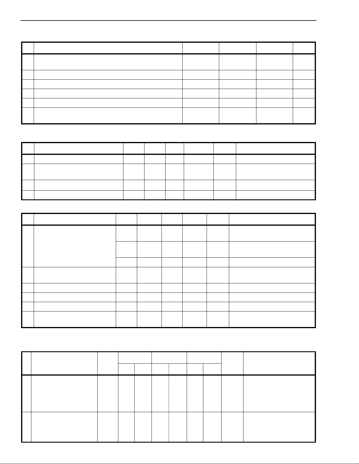
Absolute Maximum Ratings*- Voltages are with respect to V
unless otherwise stated.
EE
Parameter Symbol Min Max Units
1 Supply Voltage V
2 Analog Input Voltage V
3 Digital Input Voltage V
DD
V
SS
INA
IN
-0.3
-0.3
V
15.0
DD
+0.3
-0.3 VDD+0.3 V
VSS-0.3 VDD+0.3 V
4 Current on any I/O Pin I ±15 mA
5 Storage Tem perature T
6 Package Power Dissipation PLASTIC DIP
CERDIP
* Exceeding these values may cause permanent damage. Functional operation under these conditions is not implied.
Recommended Operating Conditions - Voltages are with respect to V
S
P
D
P
D
EE
-65 +150 °C
0.6
1.0
unless otherwise stated.
Characteris tics Sym Min Typ Max Units Test Conditio ns
1 Operating Temperature T
2 Supply Voltage V
3 Analog In put Voltage V
4 Digital In put Voltage V
DC Electrical Characteristics
†
Characteristics Sym Min Typ
DD
V
SS
INA
- Voltages are with resp e ct to V
-40 25 85 °C
O
4.5
V
EE
V
EE
V
IN
SS
V
EE=VSS
‡
Max Units Test Conditio ns
13.2
DD
V
DD
V
DD
-4.5
=0V, V
V
V
V
V
=12V unless otherwise stated.
DD
V
V
W
W
1 Quiescent Supply Current I
DD
1100µA All digital inputs at VIN=VSS or
V
DD
0.4 1.5 mA All digi tal i np uts at VIN=2.4 +
V
; VSS =7.0V
SS
5 15 mA All digi tal inp uts at V
2 Off-state Leakage Current
I
OFF
(See G.9 in Appendix)
3 Input Logic “0” level V
4 Input Logic “1” level V
5 Input Logic “1” level V
6 Input Leakage (digital pins) I
† DC Electrical Characteristics are over recommended temperature range.
‡ Typical figures are at 25°C and are for design aid only; not guaran tee d and not subject to producti on testing .
IL
IH
IH
LEAK
2.0+V
3.3 V
DC Electrical Characteristics- Switch Resistance - V
±1 ± 500 nA IVXi - VYjI = VDD - V
See Appendix, Fig. A.1
SS
0.8+V
SS
VVSS =7.5V; VEE=0V
VVSS =6.5V; VEE=0V
0.1 10 µA All digital inp uts at VIN = VSS
or V
DD
is the external DC offset applied at the analog I/O pins.
DC
Characteristics Sym 25°C 7 0°C 85°C Units Test Conditions
Typ Max Typ Max Typ Max
1 On-state V
Resistance V
=12V
DD
=10V
DD
V
= 5V
DD
R
ON
45
55
120
65
75
185
75
85
215
80
90
225
Ω
VSS=VEE=0V , VDC=VDD/2,
Ω
IV
See Appendix, Fig. A.2
Ω
(See G.1, G.2, G.3 in
Appendix)
2 Difference in on-state
resistance between two
switches
(See G.4 in Appendix)
∆R
510 10 10 ΩVDD=12V, VSS=VEE=0,
ON
V
IV
See Appendix, Fig. A.2
I = 0.4V
Xi-VYj
DC=VDD
I = 0.4V
Xi-VYj
/2,
IN
EE
=3.4V
3-18
Page 5
ISO-CMOS MT8808
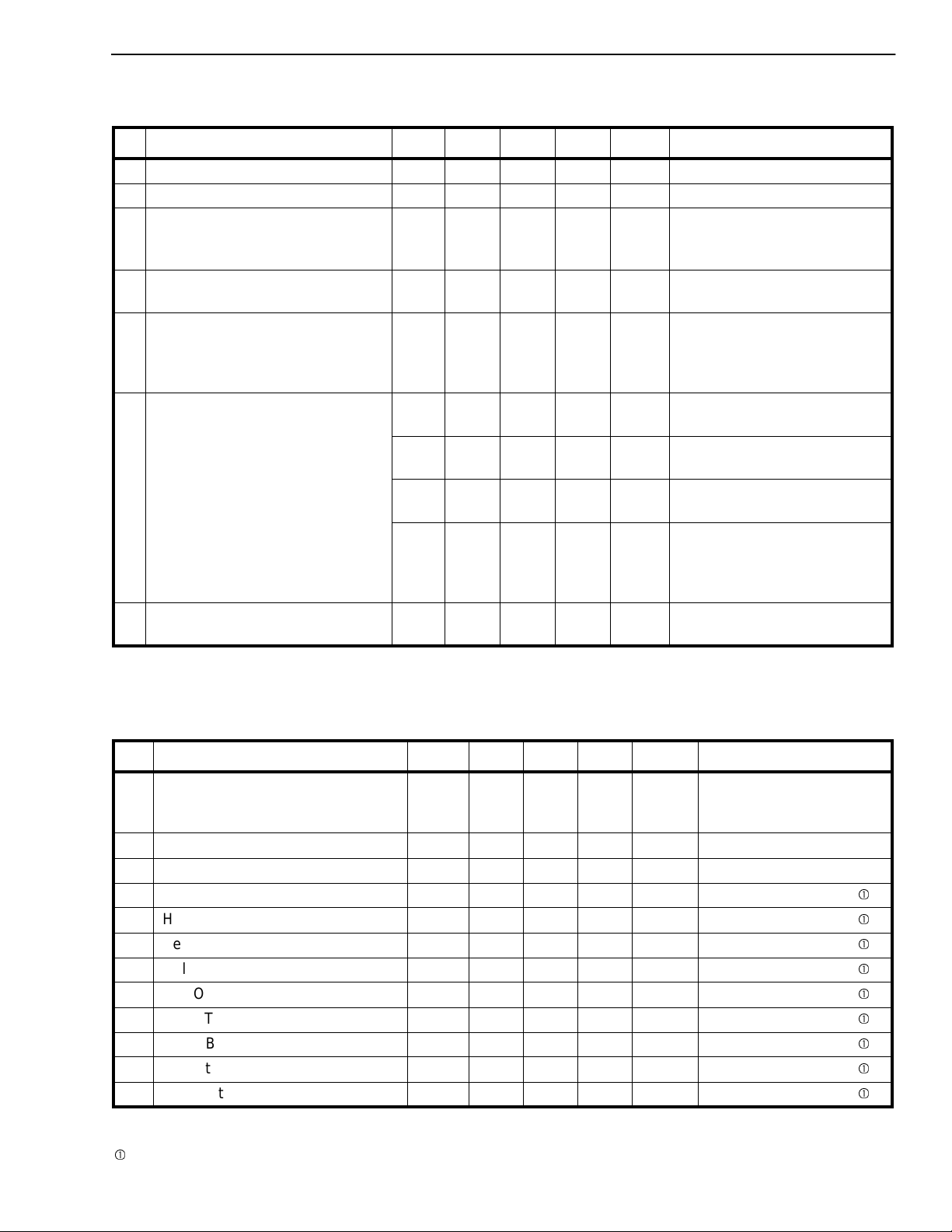
AC Electrical Characteristics† - Crosspoint Performance-Voltages are with respect to V
=-7V , unless otherwise stated.
V
EE
DD
Characteristics Sym Min Typ‡Max Units Test Co nditions
1 Switch I/O Capacitance C
2 Feedthrough Capacitance C
3 Frequency Response
F
Channel “ON”
20LOG(V
OUT/VXi
4 Total Harmonic Distortion
)=-3dB
THD 0.01 % Switch is “ON”; V
(See G.5, G.6 in Appendix)
5 Feedthrough
FDT -95 dB All Switches “OFF”; V
Channel “OFF”
Feed.=20LOG (V
OUT/VXi
)
(See G.8 in Appendix)
6 Crosstalk between any two
X
channels for switches Xi-Yi and
Xj-Yj .
Xtalk=20LOG (V
Yj/VXi
).
(See G.7 in Appendix).
S
F
3dB
talk
20 pF f=1 MHz
0.2 pF f=1 MHz
45 MHz Switch is “ON”; V
sinewave; R
= 1kΩ
L
See Appendix, Fig. A.3
sinewave f= 1k Hz; R
2Vpp sinewave f= 1kHz;
= 1kΩ.
R
L
See Appendix, Fig. A.4
-45 dB V
-90 dB V
-85 dB V
-80 dB V
=2Vpp sinewave
INA
f= 10MHz; R
=2Vpp sinewave
INA
f= 10kHz; R
=2Vpp sinewave
INA
f= 10kHz; R
=2Vpp sinewave
INA
f= 1kHz; R
L
= 75Ω.
L
= 600Ω.
L
= 1kΩ.
L
= 10kΩ.
Refer to Appendix, Fig. A.5
for test circuit.
7 Propagation delay thro ugh
t
PS
30 ns RL=1kΩ; CL=50pF
switc h
† Timing is over recommende d tempera tu re range . See Fig. 3 for control and I/O timing details.
‡ Typical figures are at 25°C and are for design aid only; not guaranteed and not subject to production testing.
Crosstal k m ea su r em e nts a re fo r Pl as tic D I PS o nl y, cross tal k va lu es f or PLCC pa ckag es are ap proximat ely 5dB b etter.
AC Electrical Charact eristics† - Control and I/O T i mings - Voltages are with respect to V
V
=-7V , unless otherwise stated.
EE
=5V, VSS=0V,
DD
Characteristics Sym Min Typ‡Max Units Test Conditions
=5V, VSS=0V,
= 2Vpp
INA
= 2Vpp
INA
=1kΩ
L
=
INA
1 Control Input crosstalk to switch
CX
talk
30 mVpp VIN=3V squarewave;
(for CS, DATA, STROBE,
Address)
2 Digital Input Capacitance C
3 Switching Frequency F
4 Setup Time DATA to STROBE t
5 Hold Time DATA to STROBE t
6 Setup Time Address to STROBE t
7 Hold Time Address to STROBE t
8 S TROBE Pulse Width t
9 RESET Pulse Width t
10 S TRO BE to Swit ch Status Dela y t
11 DATA to Switch Status Delay t
12 RE S ET to Switch S tatus Delay t
† Timing is over recommended temperature range. See Fig. 3 for control and I/O timing details.
Digital Inp ut ris e tim e (t r) an d fall tim e (tf) = 5 ns .
‡ Typical figures are at 25°C and are for design aid only; not guaran teed an d not subject to producti on testing .
Refer t o Appendix, Fi g. A.7 for te s t c irc ui t.
DI
O
DS
DH
AS
AH
SPW
RPW
S
D
R
10 ns RL= 1kΩ, CL=50pF
10 ns RL= 1kΩ, CL=50pF
10 ns RL= 1kΩ, CL=50pF
10 ns RL= 1kΩ, CL=50pF
20 ns RL= 1kΩ, CL=50pF
40 ns RL= 1kΩ, CL=50pF
10 pF f=1MHz
20 MHz
40 100 ns RL= 1kΩ, CL=50pF
50 100 ns RL= 1kΩ, CL=50pF
35 100 ns RL= 1kΩ, CL=50pF
R
=1kΩ, RL=10kΩ.
IN
See Appendix, Fig . A.6
3-19
Page 6
MT8808 ISO-CMOS
t
RPW
RESET
STROBE
ADDRESS
DATA
SWITCH*
ON
t
SPW
t
AS
50% 50%
50% 50%
t
DS
t
DH
t
AH
50% 50%
50%50%50%
OFF
t
D
t
S
t
R
t
R
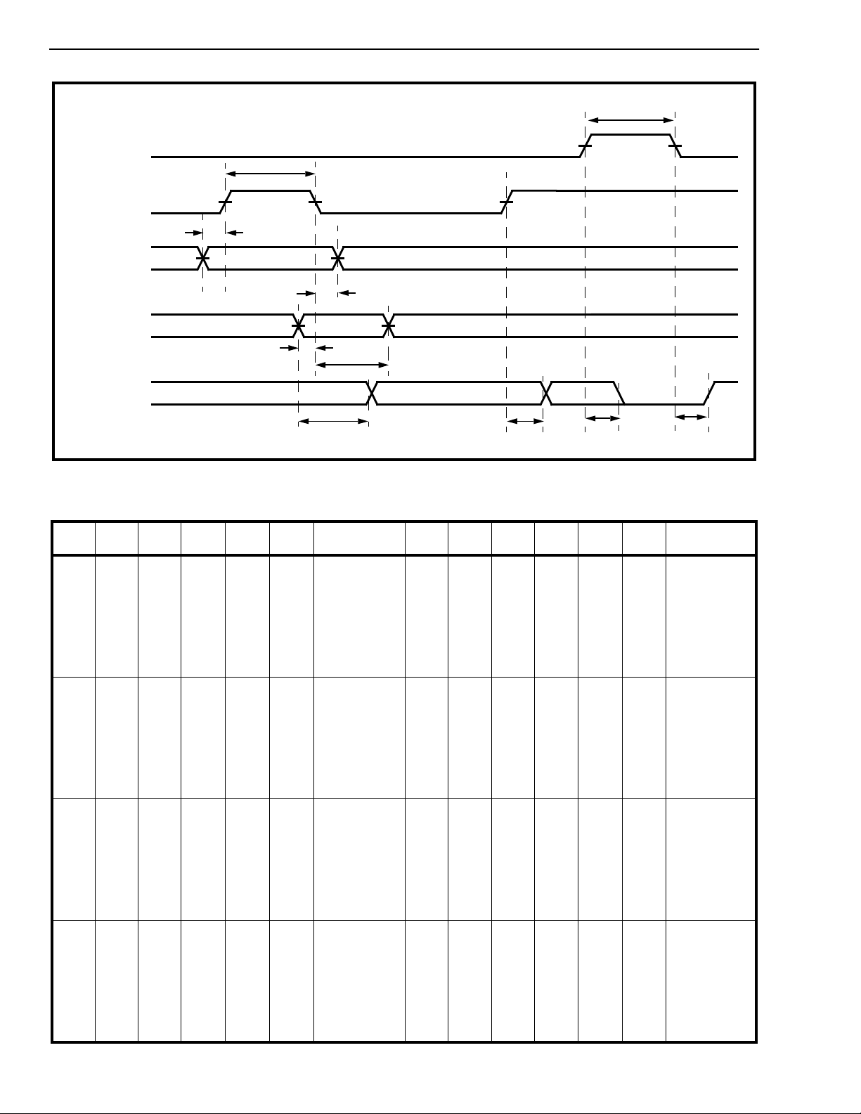
Figure 3 - Control Memory Timing Diagram
* See Appendix, Fig. A.7 for switching waveform
AY2 AY1 AY0 AX2 AX1 AX0 Connection AY2 AY1 AY0 AX2 AX1 AX0 Connection
0
0
0
0
0
0
0
0
0
0
0
0
0
0
0
0
0
0
0
0
0
0
0
0
0
0
0
0
0
0
0
0
0
0
0
0
0
0
0
0
0
0
0
0
0
0
0
0
1
1
1
1
1
1
1
1
1
1
1
1
1
1
1
1
0
0
0
0
0
0
0
0
1
1
1
1
1
1
1
1
0
0
0
0
0
0
0
0
1
1
1
1
1
1
1
1
0
0
0
0
1
1
1
1
0
0
0
0
1
1
1
1
0
0
0
0
1
1
1
1
0
0
0
0
1
1
1
1
0
0
1
1
0
0
1
1
0
0
1
1
0
0
1
1
0
0
1
1
0
0
1
1
0
0
1
1
0
0
1
1
0
1
0
1
0
1
0
1
0
1
0
1
0
1
0
1
0
1
0
1
0
1
0
1
0
1
0
1
0
1
0
1
X0 Y0
X1 Y0
X2 Y0
X3 Y0
X4 Y0
X5 Y0
X6 Y0
X7 Y0
X0 Y1
X1 Y1
X2 Y1
X3 Y1
X4 Y1
X5 Y1
X6 Y1
X7 Y1
X0 Y2
X1 Y2
X2 Y2
X3 Y2
X4 Y2
X5 Y2
X6 Y2
X7 Y2
X0 Y3
X1 Y3
X2 Y3
X3 Y3
X4 Y3
X5 Y3
X6 Y3
X7 Y3
1
1
1
1
1
1
1
1
1
1
1
1
1
1
1
1
1
1
1
1
1
1
1
1
1
1
1
1
1
1
1
1
0
0
0
0
0
0
0
0
0
0
0
0
0
0
0
0
1
1
1
1
1
1
1
1
1
1
1
1
1
1
1
1
0
0
0
0
0
0
0
0
1
1
1
1
1
1
1
1
0
0
0
0
0
0
0
0
1
1
1
1
1
1
1
1
0
0
0
0
1
1
1
1
0
0
0
0
1
1
1
1
0
0
0
0
1
1
1
1
0
0
0
0
1
1
1
1
0
0
1
1
0
0
1
1
0
0
1
1
0
0
1
1
0
0
1
1
0
0
1
1
0
0
1
1
0
0
1
1
0
1
0
1
0
1
0
1
0
1
0
1
0
1
0
1
0
1
0
1
0
1
0
1
0
1
0
1
0
1
0
1
X0 Y4
X1 Y4
X2 Y4
X3 Y4
X4 Y4
X5 Y4
X6 Y4
X7 Y4
X0 Y5
X1 Y5
X2 Y5
X3 Y5
X4 Y5
X5 Y5
X6 Y5
X7 Y5
X0 Y6
X1 Y6
X2 Y6
X3 Y6
X4 Y6
X5 Y6
X6 Y6
X7 Y6
X0 Y7
X1 Y7
X2 Y7
X3 Y7
X4 Y7
X5 Y7
X6 Y7
X7 Y7
3-20
Table 1. Address Decode Truth Table
 Loading...