

Datasheet MT28F160A3FD-11T, MT28F160A3FD-11TET, MT28F160A3FD-9T, MT28F160A3FD-9TET Datasheet (MICRON)
Page 1
1
1 Meg x 16 Enhanced Boot Block Flash Memory ©2001, Micron Technology, Inc.
MT28F160A3_3.p65 – Rev. 3, Pub. 8/01
1 MEG x 16
ENHANCED BOOT BLOCK FLASH MEMORY
ADVANCE
‡
‡
PRODUCTS AND SPECIFICATIONS DISCUSSED HEREIN ARE FOR EVALUATION AND REFERENCE PURPOSES ONLY AND
ARE SUBJECT TO CHANGE BY MICRON WITHOUT NOTICE. PRODUCTS ARE ONLY WARRANTED BY MICRON TO MEET
MICRON’S PRODUCTION DATA SHEET SPECIFICATIONS.
FLASH MEMORY MT28F160A3
Low Voltage, Extended Temperature
GENERAL DESCRIPTION
The MT28F160A3 is a nonvolatile, electrically blockerasable (flash), programmable, read-only memory containing 16,777,216 bits organized as 1,048,576 words
(16 bits).
The MT28F160A3 is manufactured on 0.22µm process
technology in a 48-ball FBGA package. The device has an
I/O supply of 2.7V (MIN). Programming in production is
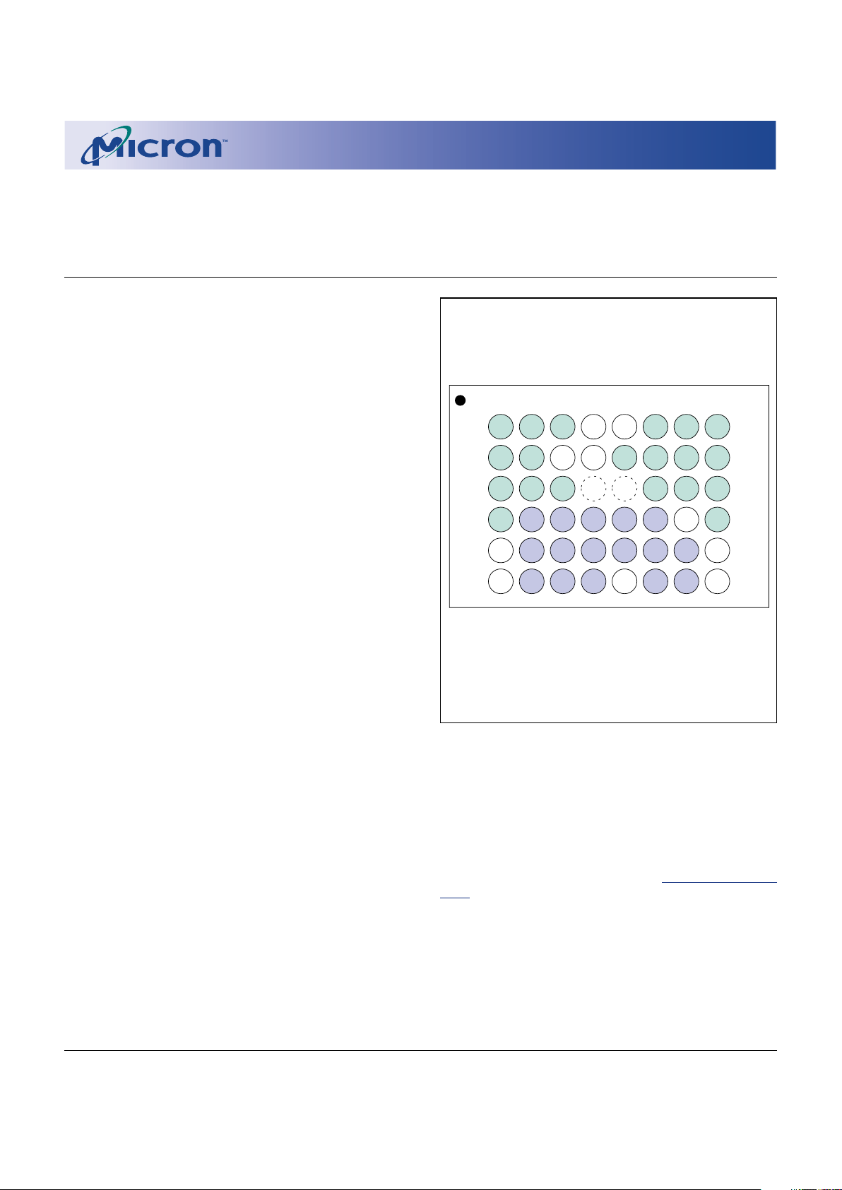
BALL ASSIGNMENT (Top View)
46-Ball FBGA
FEATURES
• Thirty-nine erase blocks:
Two 4K-word boot blocks (protected)
Six 4K-word parameter blocks
Thirty-one 32K-word main memory blocks
•VCC, VCCQ and VPP voltages:
2.7V–3.3V VCC and VPP
2.7V–3.3V VCCQ*
5V VPP fast programming voltage
• Address access times:
90ns, 110ns at 2.7V–3.3V
• Low power consumption:
Standby and deep power-down mode < 1µA
(typical ICC)
Automatic power saving feature (APS mode)
• Enhanced WRITE/ERASE SUSPEND (1µs typical)
• Industry-standard command set compatibility
• Hardware block protection
OPTIONS NUMBER
• Timing
90ns access -9
110ns access -11
• Boot Block Starting Address
Top (FFFFFH) T
Bottom (00000H) B
• Package
46-ball FBGA (6 x 8 ball grid) FD
• Temperature Range
Commercial (0°C to +70°C) None
Extended (-40°C to +85°C) ET
*Lower VCCQ ranges are available upon request.
Part Number Example:
MT28F160A3FD-11 TET
A
B
C
D
E
F
A13
A14
A15
A16
V
CC
Q
V
SS
A19
A17
A6
DQ8
DQ9
DQ10
WP#
A18
DQ2
DQ3
V
CC
V
PP
RP#
DQ11
DQ12
DQ4
A8
WE#
A9
DQ5
DQ6
DQ13
A4
A2
A1
A0
V
SS
OE#
A7
A5
A3
CE#
DQ0
DQ1
A11
A10
A12
DQ14
DQ15
DQ7
1 2 3 4 5 6 7 8
(Ball Down)
NOTE: See page 3 for Ball Description Table.
See last page for mechanical drawing.
accomplished by using high voltage which can be supplied on a separate line.
The embedded WORD WRITE and BLOCK ERASE
functions are fully automated by an on-chip write state
machine (WSM), which simplifies these operations and
relieves the system processor of secondary tasks. The
WSM status can be monitored by an on-chip status
register to determine the progress of program/erase tasks.
Please refer to Micron’s Web site (www.micron.com/
flash) for the latest data sheet.
DEVICE MARKING
Due to the size of the package, Micron’s standard part
number is not printed on the top of each device. Instead,
an abbreviated device mark comprised of a five-digit
alphanumeric code is used. The abbreviated device marks
are cross referenced to Micron part numbers in
Table 1.
Page 2
2
1 Meg x 16 Enhanced Boot Block Flash Memory Micron Technology, Inc., reserves the right to change products or specifications without notice.
MT28F160A3_3.p65 – Rev. 3, Pub. 8/01 ©2001, Micron Technology, Inc.
1 MEG x 16
ENHANCED BOOT BLOCK FLASH MEMORY
ADVANCE
Table 1
Cross Reference for Abbreviated
Device Marks
1
PRODUCT SAMPLE
PART NUMBER MARKING MARKING
MT28F160A3FD-9 BET FW310 FX310
MT28F160A3FD-9 TET FW311 FX311
MT28F160A3FD-11 BET FW312 FX312
MT28F160A3FD-11 TET FW313 FX313
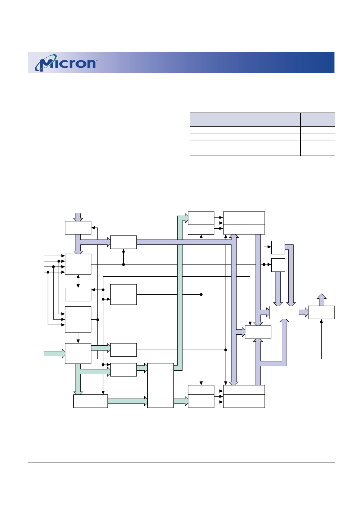
FUNCTIONAL BLOCK DIAGRAM
Address
Input
Buffer
X DEC
Y/Z DEC
Data Input
Buffer
APS
Control
Data
Comparator
Output
Multiplexer
Address
CNT WSM
Output
Buffer
Status
Reg.
ID
Reg.
WSM
Program/
Erase Change
Pump Voltage
Switch
Address Latch
DQ0–DQ15
DQ0–DQ15
CSM
RP#
CE#
X DEC
Y/Z DEC
WE#
OE#
I/O Logic
A0–A19
Address
Multiplexer
Bank b Blocks
Y/Z Gating/Sensing
Data
Register
Bank a Blocks
Y/Z Gating/Sensing
ARCHITECTURE
The MT28F160A3 flash contains eight 4K-word parameter blocks and thirty-one 32K-word blocks. The first
two 4K-word blocks are called boot blocks and are locked
with WP# control. Memory is organized by using a blocked
architecture to allow independent erasure of selected
memory blocks. Any address within a block address range
selects that block for the required READ, WRITE, or ERASE
operation (see Figures 1 and 2).
NOTE: 1. The mechanical sample marking is FY310.
Page 3
3
1 Meg x 16 Enhanced Boot Block Flash Memory Micron Technology, Inc., reserves the right to change products or specifications without notice.
MT28F160A3_3.p65 – Rev. 3, Pub. 8/01 ©2001, Micron Technology, Inc.
1 MEG x 16
ENHANCED BOOT BLOCK FLASH MEMORY
ADVANCE
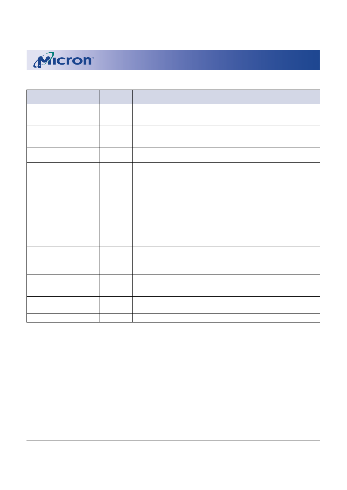
BALL DESCRIPTIONS
46-BALL FBGA
NUMBERS SYMBOL TYPE DESCRIPTION
3B WE# Input Write Enable: Determines if a given cycle is a WRITE cycle. If WE# is
LOW, the cycle is either a WRITE to the command state machine (CSM)
or to the memory array.
5A WP# Input Write Protect: Unlocks the boot blocks when HIGH if VPP = 2.7V–3.3V
or 5V (WRITE only) and RP# = VIH for WRITE or ERASE. Does not affect
WRITE or ERASE operation on other blocks.
7D CE# Input Chip Enable: Activates the device when LOW. When CE# is HIGH, the
device is disabled and goes into standby power mode.
4B RP# Input Reset/Power-Down: When LOW, RP# clears the status register, sets the
write state machine (WSM) to the array read mode and places the
device in deep power-down mode. All inputs, including CE#, are
“Don’t Care,” and all outputs are High-Z. RP# must be held at VIH
during all other modes of operation.
8F OE# Input Output Enable: Enables data output buffers when LOW. When OE# is
HIGH, the output buffers are disabled.
1A, 1B, 1C, 1D, A0-A19 Input Address Inputs: These address inputs select a unique, 16-bit word out
2A, 2B, 2C, 3A, of the 1,048,576 available.
3C, 5B, 6A, 6B,
6C, 7A, 7B, 7C,
8A, 8B, 8C, 8D
2D, 2E, 2F, 3D, DQ0-DQ15 Input/ Data I/O: These data I/O are data output lines during any READ
3E, 3F, 4D, 4E, Output operation or data input lines during a WRITE. Data I/O are used to
4F, 5D, 5E, 6D, input commands to the CSM.
6E, 6F, 7E, 7F
4A VPP Supply Write/Erase Supply Voltage: From a WRITE or ERASE CONFIRM until
completion of the operation, VPP must be 2.7V–3.3V or 5V (WRITE
only). VPP = “Don’t Care” during all other operations.
5F VCC Supply Power Supply: 2.7V–3.3V.
1E VCCQ Supply I/O Supply Voltage: 2.7V–3.3V.
1F, 8E VSS Supply Ground.
Page 4
4
1 Meg x 16 Enhanced Boot Block Flash Memory Micron Technology, Inc., reserves the right to change products or specifications without notice.
MT28F160A3_3.p65 – Rev. 3, Pub. 8/01 ©2001, Micron Technology, Inc.
1 MEG x 16
ENHANCED BOOT BLOCK FLASH MEMORY
ADVANCE
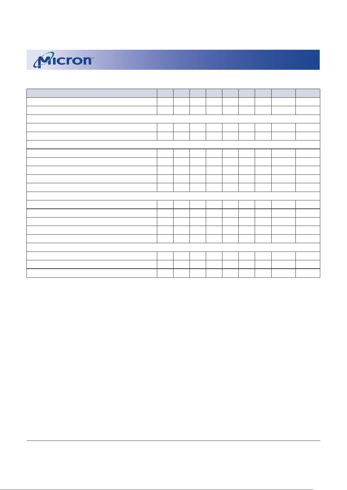
NOTE: 1. L = VIL (LOW), H = VIH (HIGH), X = VIL or VIH (“Don’t Care”).
2. VPPH = 2.7V–3.3V for ERASE, and VPPH = 2.7V–3.3V or 5V for WRITE.
3. Operation must be preceded by ERASE SETUP command.
4. Operation must be preceded by WRITE SETUP command.
5. The READ ARRAY command must be issued before reading the array after writing or erasing.
6. See Table 3 for the IDENTIFY DEVICE command.
TRUTH TABLE
1
FUNCTION RP# CE# OE# WE# WP# V
PP
A0 DQ0-DQ7 DQ8-DQ15
Standby H H XXXXXHigh-Z High-Z
RESET L XXXXXXHigh-Z High-Z
READING
READ H L L H X X X Data-Out Data-Out
Output Disable H L H H X X X High-Z High-Z
WRITE/ERASE (EXCEPT BOOT BLOCKS)
2
ERASE SETUP H L H L X X X 20H X
ERASE CONFIRM
3
HLHLXVPPH X D0H X
WRITE SETUP H L H L X X X 10H/40H X
WRITE
4
HLHLXVPPH X Data-In Data-In
READ ARRAY
5
HLHLXXX FFH X
WRITE/ERASE (BOOT BLOCKS)
2
ERASE SETUP H L H L X X X 20H X
ERASE CONFIRM
3
HLHLHVPPH X D0H X
WRITE SETUP H L H L X X X 10H/40H X
WRITE
4
HLHLHVPPH X Data-In Data-In
READ ARRAY
5
HLHLXXX FFH X
DEVICE IDENTIFICATION
6
Manufacturer H L L H X X L 2CH 00H
Device (top boot) H L L H X X H 90H 44H
Device (bottom boot) H L L H X X H 91H 44H
Page 5
5
1 Meg x 16 Enhanced Boot Block Flash Memory Micron Technology, Inc., reserves the right to change products or specifications without notice.
MT28F160A3_3.p65 – Rev. 3, Pub. 8/01 ©2001, Micron Technology, Inc.
1 MEG x 16
ENHANCED BOOT BLOCK FLASH MEMORY
ADVANCE
8 x 4K-Word Blocks
32K-Word Block
32K-Word Block
32K-Word Block
32K-Word Block
32K-Word Block
32K-Word Block
32K-Word Block
32K-Word Block
32K-Word Block
32K-Word Block
32K-Word Block
32K-Word Block
32K-Word Block
32K-Word Block
32K-Word Block
32K-Word Block
32K-Word Block
32K-Word Block
32K-Word Block
32K-Word Block
32K-Word Block
32K-Word Block
32K-Word Block
32K-Word Block
32K-Word Block
32K-Word Block
32K-Word Block
32K-Word Block
32K-Word Block
32K-Word Block
32K-Word Block
Boot Blocks
4K-Word Block
4K-Word Block
4K-Word Block
4K-Word Block
4K-Word Block
4K-Word Block
4K-Word Block
4K-Word Block
Parameter
Blocks
0
1
2
3
4
5
6
7
8
9
10
11
12
13
14
15
16
17
18
19
20
21
22
23
24
25
26
27
28
29
30
31
FFFFFh
F8000h
F7FFFh
F0000h
EFFFFh
E8000h
E7FFFh
E0000h
DFFFFh
D8000h
D7FFFh
D0000h
CFFFFh
C8000h
C7FFFh
C0000h
BFFFFh
B8000h
B7FFFh
B0000h
AFFFFh
A8000h
A7FFFh
A0000h
9FFFFh
98000h
97FFFh
90000h
8FFFFh
88000h
87FFFh
80000h
7FFFFh
78000h
77FFFh
70000h
6FFFFh
68000h
67FFFh
60000h
5FFFFh
58000h
57FFFh
50000h
4FFFFh
48000h
47FFFh
40000h
3FFFFh
38000h
37FFFh
30000h
2FFFFh
28000h
27FFFh
20000h
1FFFFh
18000h
17FFFh
10000h
0FFFFh
08000h
07FFFh
00000h
FFFFFh
FF000h
FEFFFh
FE000h
FDFFFh
FD000h
FCFFFh
FC000h
FBFFFh
FB000h
FAFFFh
FA000h
F9FFFh
F9000h
F8FFFh
F8000h
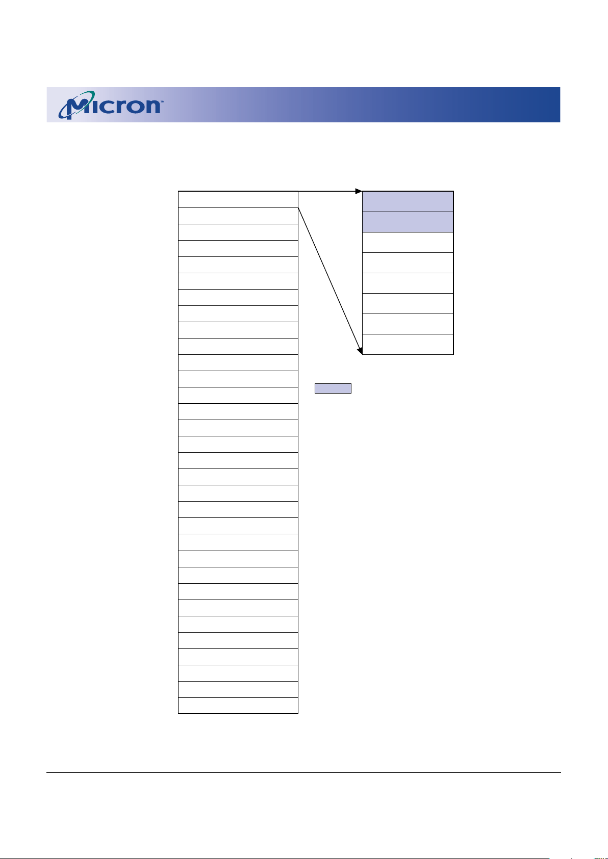
ADDRESS RANGE
Figure 1
Top Boot Block Memory Address Map
NOTE: 1. The two 4K-word blocks (boot blocks) can only be locked/unlocked by WP#.
Page 6
6
1 Meg x 16 Enhanced Boot Block Flash Memory Micron Technology, Inc., reserves the right to change products or specifications without notice.
MT28F160A3_3.p65 – Rev. 3, Pub. 8/01 ©2001, Micron Technology, Inc.
1 MEG x 16
ENHANCED BOOT BLOCK FLASH MEMORY
ADVANCE
32K-Word Block
32K-Word Block
32K-Word Block
32K-Word Block
32K-Word Block
32K-Word Block
32K-Word Block
32K-Word Block
32K-Word Block
32K-Word Block
32K-Word Block
32K-Word Block
32K-Word Block
32K-Word Block
32K-Word Block
32K-Word Block
32K-Word Block
32K-Word Block
32K-Word Block
32K-Word Block
32K-Word Block
32K-Word Block
32K-Word Block
32K-Word Block
32K-Word Block
32K-Word Block
32K-Word Block
32K-Word Block
32K-Word Block
32K-Word Block
32K-Word Block
8 x 4K-Word Blocks
Boot Blocks
4K-Word Block
4K-Word Block
4K-Word Block
4K-Word Block
4K-Word Block
4K-Word Block
4K-Word Block
4K-Word Block
Parameter
Blocks
31
30
29
28
27
26
25
24
23
22
21
20
19
18
17
16
15
14
13
12
11
10
9
8
7
6
5
4
3
2
1
0
FFFFFh
F8000h
F7FFFh
F0000h
EFFFFh
E8000h
E7FFFh
E0000h
DFFFFh
D8000h
D7FFFh
D0000h
CFFFFh
C8000h
C7FFFh
C0000h
BFFFFh
B8000h
B7FFFh
B0000h
AFFFFh
A8000h
A7FFFh
A0000h
9FFFFh
98000h
97FFFh
90000h
8FFFFh
88000h
87FFFh
80000h
7FFFFh
78000h
77FFFh
70000h
6FFFFh
68000h
67FFFh
60000h
5FFFFh
58000h
57FFFh
50000h
4FFFFh
48000h
47FFFh
40000h
3FFFFh
38000h
37FFFh
30000h
2FFFFh
28000h
27FFFh
20000h
1FFFFh
18000h
17FFFh
10000h
0FFFFh
08000h
07FFFh
00000h
07FFFh
07000h
06FFFh
06000h
05FFFh
05000h
04FFFh
04000h
03FFFh
03000h
02FFFh
02000h
01FFFh
01000h
00FFFh
00000h
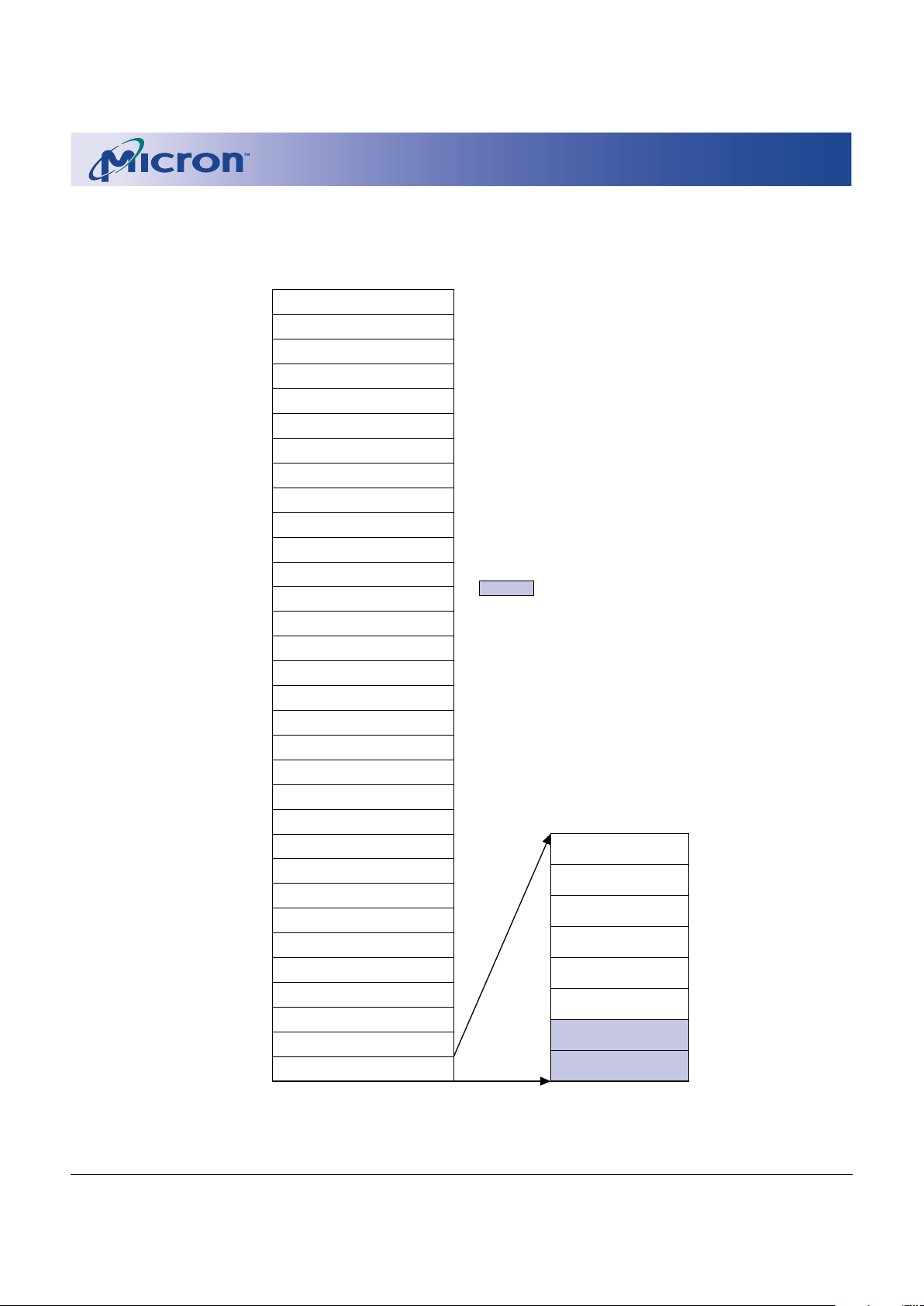
ADDRESS RANGE
Figure 2
Bottom Boot Block Memory Address Map
NOTE: 1. The two 4K-word blocks (boot blocks) can only be locked/unlocked by WP#.
Page 7
7
1 Meg x 16 Enhanced Boot Block Flash Memory Micron Technology, Inc., reserves the right to change products or specifications without notice.
MT28F160A3_3.p65 – Rev. 3, Pub. 8/01 ©2001, Micron Technology, Inc.
1 MEG x 16
ENHANCED BOOT BLOCK FLASH MEMORY
ADVANCE
MEMORY ORGANIZATION
The MT28F160A3 memory array is segmented into 31
blocks of 32K words, along with eight 4K-word parameter
blocks. The device is available with block architecture
mapped in either of the two configurations: the boot
blocks located at the top or at the bottom of the memory
array, as required by different microprocessors. The
MT28F160A3 top boot configuration with the blocks and
address ranges is shown in Figure 1 and the bottom boot
configuration in Figure 2.
The boot blocks are used to store key system data and
are seldom changed during normal operation. When the
WP# is at VIL , the contents of the boot block cannot be
erased or reprogrammed. The boot block contents can be
changed only through proper command sequences when
WP# is HIGH (see Table 5).
COMMAND STATE MACHINE
Commands are issued to the command state machine (CSM) using standard microprocessor write timings. The CSM acts as an interface between the external
microprocessor and the internal write state machine
(WSM). The available commands are listed in Table 2,
and the descriptions of these commands are shown in
Table 3. Program and erase algorithms are automated by
an on-chip WSM. Once a valid program/erase command
sequence is entered, the WSM executes the appropriate
algorithm, which generates the necessary timing signals
to control the device internally to accomplish the requested operation. A command is valid only if the exact
sequence of WRITEs is completed. After the WSM completes its task, the WSM status bit (SR7) is set to a logic
HIGH level (1), allowing the CSM to respond to the full
command set again.
OPERATION
Device operations are selected by entering standard
JEDEC 8-bit command codes with conventional microprocessor timings into an on-chip CSM through I/Os
DQ0-DQ7. When the device is powered up, internal reset
circuitry initializes the chip to a read array mode of operation. Changing the mode of operation requires that a
command code be entered into the CSM. The on-chip
status register allows the progress of various operations
to be monitored. The status register is interrogated by
entering a READ STATUS REGISTER command onto the
CSM (cycle 1) and reading the register data on I/Os DQ0DQ7 (cycle 2). Status register bits SR0-SR7 correspond to
DQ0-DQ7 (see Table 3).
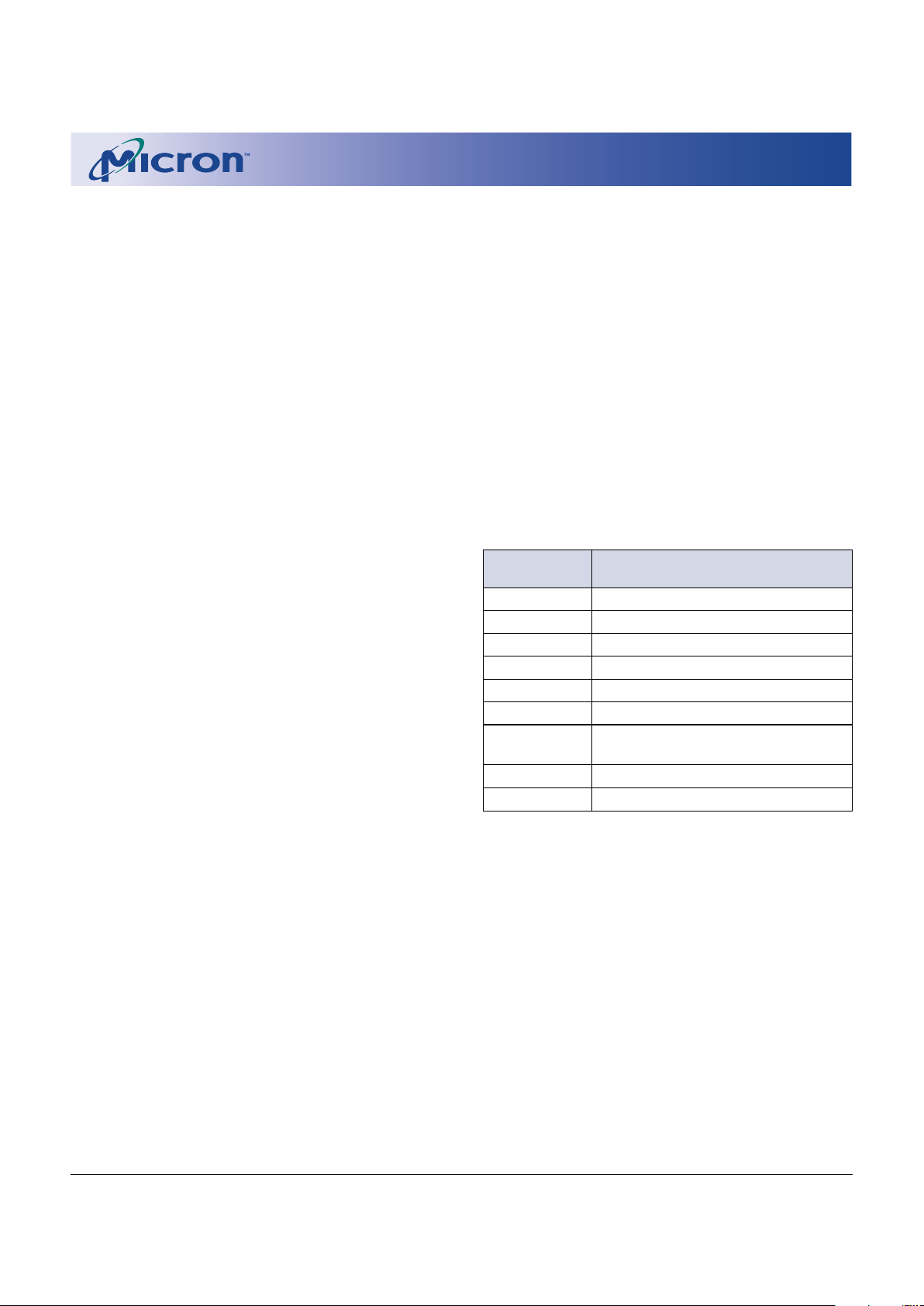
Table 2
Command State Machine Codes for
Device Mode Selection
COMMAND CODE ON
DQ0-DQ7 DEVICE MODE
10h/40h Write setup/alternate write setup
20h Block erase setup
50h Clear status register
70h Read status register
90h Identify device
B0h Program/erase suspend
D0h Program/erase resume
Erase confirm
FFh Read array
60h, 0Fh, AFh Reserved
Page 8
8
1 Meg x 16 Enhanced Boot Block Flash Memory Micron Technology, Inc., reserves the right to change products or specifications without notice.
MT28F160A3_3.p65 – Rev. 3, Pub. 8/01 ©2001, Micron Technology, Inc.
1 MEG x 16
ENHANCED BOOT BLOCK FLASH MEMORY
ADVANCE
Table 3
Command Definitions
FIRST CYCLE SECOND CYCLE
COMMAND OPERATION ADDRESS CSM/INPUT OPERATION ADDRESS DATA
READ ARRAY WRITE X FFh READ WA AD
IDENTIFY DEVICE WRITE X 90h READ IA ID
READ STATUS REGISTER WRITE X 70h READ BA SRD
WORD PROGRAM WRITE X 10h/40h WRITE WA PD
BLOCK ERASE WRITE X 20h WRITE BA D0h
PROGRAM/ERASE SUSPEND WRITE X B0h
PROGRAM/ERASE RESUME WRITE X D0h
CLEAR STATUS REGISTER WRITE X 50h
COMMAND DEFINITIONS
Once a specific command code has been entered, the
WSM executes an internal algorithm generating the necessary timing signals to program, erase, and verify data.
See Table 3 for the CSM command definitions and data
for each of the bus cycles.
NOTE: 1. The command data is written through DQ0-DQ7
2. ID = Manufacturer ID: 002Ch; Device ID (Top Boot): 4490h; Device ID (Bottom Boot): 4491h
3. IA = Identify address: 00000h for manufacturer code and 00001h for device code
4. BA = Any address within the block to be selected
5. WA = Word address
6. AD = Array data
7. SRD = Data read from status register
8. PD = Data to be written at location WA
9. X = Don’t Care
Page 9

9
1 Meg x 16 Enhanced Boot Block Flash Memory Micron Technology, Inc., reserves the right to change products or specifications without notice.
MT28F160A3_3.p65 – Rev. 3, Pub. 8/01 ©2001, Micron Technology, Inc.
1 MEG x 16
ENHANCED BOOT BLOCK FLASH MEMORY
ADVANCE
STATUS REGISTER
The status register allows the user to determine
whether the state of a PROGRAM/ERASE operation is
pending or complete. The status register is monitored by
toggling OE# and CE# and by reading the resulting status
code on I/Os DQ0-DQ7. The high-order I/Os (DQ8-DQ15)
are set to 00h internally, so only the low-order I/Os (DQ0DQ7) need interpreting.
Register data is updated on the falling edge of OE# or
CE#. The latest falling edge of either of these two signals
updates the latch within a given READ cycle. Latching the
data prevents errors from occurring if the register input
changes during a status register monitoring. To ensure
that the status register output contains updated status
data, CE# or OE# must be toggled for each subsequent
STATUS READ.
The status register provides the internal state of the
WSM to the external microprocessor. During periods
when the WSM is active, the status register can be polled
to determine the WSM status. Table 4 defines the status
register bits.
After monitoring the status register during a PROGRAM/ERASE, the data appearing on DQ0-DQ7 remains
as status register data until a new command is issued to
the CSM. To return the device to other modes of operation, a new command must be issued to the CSM.
COMMAND STATE MACHINE
OPERATIONS
The CSM decodes instructions for read, read device
identification code, read status register, clear status register, program, erase, erase suspend, erase resume, program suspend, and program resume. The 8-bit command code is input to the device on DQ0-DQ7 (see Table
2 for CSM codes). During a PROGRAM or ERASE cycle,
the CSM informs the WSM that a PROGRAM or ERASE
cycle has been requested.
During a PROGRAM cycle, the WSM controls the program sequences and the CSM responds to a PROGRAM
SUSPEND command only. During an ERASE cycle, the
CSM responds to an ERASE SUSPEND command only.
When the WSM has completed its task, the WSM status
bit (SR7) is set to a logic HIGH level and the CSM responds
to the full command set. The CSM stays in the current
command state until the microprocessor issues another
command.
The WSM successfully initiates an ERASE or PROGRAM operation only when VPP is within its correct voltage range. For data protection, it is required that RP# be
held at a logic LOW level during a CPU reset.
CLEAR STATUS REGISTER
The WSM can set to “1” the block lock status bit (SR1),
the VPP status bit (SR3), the program status bit (SR4), and
the erase status bit (SR5) of the status register. The CLEAR
STATUS REGISTER command (50h) allows the external
microprocessor to clear these status bits and synchronize to internal operations. After issuing this command,
the status bits are cleared and the device returns to the
read array mode.
READ OPERATIONS
Three READ operations are available: read array, read
device identification code, and read status register.
READ ARRAY
The array is read by entering the command code FFh
on DQ0-DQ7. Control signals CE# and OE# must be at a
logic LOW level (VIL) and WE# and RP# must be at a logic
HIGH level (VIH) to read data from the array. Data is
available on DQ0-DQ15. Any valid address within any of
the blocks selects that address and allows data to be read
from that address. Upon initial power-up, the device
defaults to the read array mode.
READ DEVICE IDENTIFICATION CODE
Device identification codes are read by entering command code 90h on DQ0-DQ7. Two bus cycles are required for this operation, the first to enter the command
code and the second to read the selected code. Control
signals CE# and OE# must be at a logic LOW level (VIL)
and WE# and RP# must be at a logic HIGH level (VIH). The
manufacturer code is obtained on DQ0-DQ15 in the second cycle, after the identify address 00000h is latched.
The device code is obtained on DQ0-DQ15 in the second
cycle, after the identify address 00001h is latched (see
Table 3).
READ STATUS REGISTER
The status register is read by entering the command
code 70h on DQ0-DQ7. Control signals CE# and OE#
must be at a logic LOW level (VIL), and WE# and RP# must
be at a logic HIGH level (VIH). Two bus cycles are required
for this operation: one to enter the command code, and
one to read the status register. The status register contents are updated on the falling edge of CE# or OE#,
whichever occurs last within the cycle.
Page 10

10
1 Meg x 16 Enhanced Boot Block Flash Memory Micron Technology, Inc., reserves the right to change products or specifications without notice.
MT28F160A3_3.p65 – Rev. 3, Pub. 8/01 ©2001, Micron Technology, Inc.
1 MEG x 16
ENHANCED BOOT BLOCK FLASH MEMORY
ADVANCE
Table 4
Status Register
STATUS
BIT # STATUS REGISTER BIT DESCRIPTION
SR7
WRITE STATE MACHINE STATUS (WSM)
If SR7 = 0 (busy), the WSM has not completed an ERASE or
1 = Ready PROGRAM operation. If SR7 = 1 (ready), other operations can be
0 = Busy performed.
SR6 ERASE SUSPEND STATUS If SR6 = 1, WSM halts execution, indicating that the ERASE
1 = ERASE SUSPEND operation has been suspended. SR6 remains “1” until an ERASE
0 = ERASE in progress or RESUME command is issued.
ERASE complete
SR5 ERASE STATUS SR5 = 0 indicates that a BLOCK ERASE has been successful. SR5 = 1
1 = BLOCK ERASE error indicates that an erase has failed; therefore, the WSM has completed
0 = BLOCK ERASE successful the maximum allowable erase pulses determined by the internal
algorithm but which were insufficient to completely erase the device.
SR4 PROGRAM STATUS SR4 = 0 indicates successful programming has occurred at the
1 = PROGRAM error address location. SR4 = 1 indicates the WSM was unable to
0 = PROGRAM successful correctly program the addressed location.
SR3 VPP STATUS SR3 provides status of VPP during programming.
1 = Program abort VPP range error
0 = VPP good
SR2 PROGRAM SUSPEND STATUS If SR2 = 1, WSM halts execution, indicating the PROGRAM
1 = PROGRAM suspended operation has been suspended. SR2 stays “1” until a PROGRAM
0 = PROGRAM in progress or RESUME command is issued.
PROGRAM complete
SR1 BLOCK LOCK STATUS SR1 = 1 indicates that the address block is locked when WP# = VIL.
1 = Block locked Any attempt to program/erase this block will abort the operation
0 = Block not locked and the device will return to read status mode.
SR0 RESERVED
NOTE: 1. After a PROGRAM/ERASE command is issued and confirmed, status bit SR7 goes LOW to indicate that the operation is
in progress. If SR7 = 1 (ready), other polling operations can be performed. Until this occurs, the other status bits are
not valid. SR7 is not updated automatically at the completion of a WSM task; therefore, if the WSM status bit shows
busy (0), OE# and CE# must be toggled periodically to determine when the WSM has completed an operation (SR7 =
1).
2. When an ERASE SUSPEND command is issued, the WSM halts execution and sets SR6 = 1, indicating that the ERASE
operation has been suspended. The WSM status bit is also set to HIGH (SR7 = 1), indicating that the ERASE SUSPEND
operation has been completed successfully.
3. During an ERASE error, the SR5 bit is set (SR5 = 1), while SR5 = 0 indicates that a successful block erasure has occurred.
4. If the WSM is unable to program the addressed location correctly, the SR4 bit is set (SR4 = 1) and
SR4 = 0 indicates that a successful programming operation has occurred at the addressed block location. Information
concerning the status of VPP during programming/erasure is provided by SR3. If VPP is lower than VPPLK after a
PROGRAM/ERASE command has been issued, SR3 is set to a “1,” indicating that the PROGRAM/ERASE operation has
aborted due to a low VPP.
5. During a PROGRAM SUSPEND command, the WSM halts execution and the SR2 bit is set, indicating that the PROGRAM operation has been suspended. This bit remains ”1” until a PROGRAM RESUME command is issued. The WSM
status bit is also set to HIGH (SR7 = 1), indicating that the PROGRAM SUSPEND operation has been completed
successfully.
6. A proper block address must be provided in an ERASE operation. If that addressed block is protected, then the SR1 bit
is set (SR1 = 1) when WP# = VIL. If that block is not protected, then SR1 = 0.
Page 11

11
1 Meg x 16 Enhanced Boot Block Flash Memory Micron Technology, Inc., reserves the right to change products or specifications without notice.
MT28F160A3_3.p65 – Rev. 3, Pub. 8/01 ©2001, Micron Technology, Inc.
1 MEG x 16
ENHANCED BOOT BLOCK FLASH MEMORY
ADVANCE
PROGRAMMING OPERATIONS
There are two CSM commands for programming: program setup and alternate program setup (see Table 2).
After the desired command code is entered, the WSM
takes over and correctly sequences the device to complete the program operation. Monitoring of the WRITE
operation is possible through the status register (see the
Status Register section). During this time, the CSM responds only to a PROGRAM SUSPEND command until
the PROGRAM operation has been completed, after which
all commands to the CSM become valid again. (See Figure 3 for programming operation.)
During programming, VPP must remain in the
appropriate VPP voltage range as shown in the recommended operating conditions table. Different combinations of RP#, WP#, and VPP voltage levels ensure that data
in certain blocks are secure and therefore cannot be
programmed (see Table 5 for a list of combinations).
Only “0s” are written and compared during a PROGRAM
operation. If “1s” are programmed, the memory cell contents do not change and no error occurs.
PROGRAM SUSPENSION
The PROGRAM operation can be suspended by
issuing a PROGRAM SUSPEND command (B0h). The
PROGRAM SUSPEND command typically takes 1µs to
execute, and the device is then in program suspend mode.
Once the WSM has reached the suspend state, it allows
the CSM to respond only to READ ARRAY, READ STATUS
REGISTER, and PROGRAM RESUME commands. During
the PROGRAM SUSPEND operation, array data should
be read from an address other than the one being programmed. To resume the PROGRAM operation, a PROGRAM RESUME command (D0h) must be issued to cause
the CSM to clear the suspend state previously set. (See
Figure 6 for PROGRAM SUSPEND and PROGRAM
RESUME.)
ERASE OPERATIONS
An ERASE operation must be used to initialize all bits
in an array block to “1s.” After BLOCK ERASE CONFIRM
is issued, the CSM responds only to an ERASE SUSPEND
command until the WSM completes its task.
Block erasure inside the memory array sets all bits
within the addressed block to logic 1s. Erase is accomplished only by blocks; data at single address locations
within the array cannot be erased individually. The block
to be erased is selected by using any valid address within
that block. Note that different combinations of RP#, WP#
and VPP voltage levels ensure that data in certain blocks
are secure and therefore cannot be erased (see Table 5 for
a list of combinations). Block erasure is initiated by a
command sequence to the CSM: block erase setup (20h)
followed by block erase confirm (D0h) (see Figure 4). A
two-command erase sequence protects against accidental erasure of memory contents.
When the BLOCK ERASE CONFIRM command is complete, the WSM automatically executes a sequence of
events to complete the block erasure. During this sequence, the block is programmed with logic 0s, data is
verified, all bits in the block are erased, and finally verification is performed to ensure that all bits are correctly
erased. Monitoring of the ERASE operation is possible
through the status register (see the Status Register section).
ERASE SUSPENSION
During the execution of an ERASE operation, the
ERASE SUSPEND command (B0h) can be entered to direct the WSM to suspend the ERASE operation. The ERASE
SUSPEND command typically takes 1µs to execute, and
the device is then in erase suspend mode. Once the WSM
has reached the suspend state, it allows the CSM to
respond only to the READ ARRAY, READ STATUS REGISTER, ERASE RESUME and PROGRAM commands. Dur-
Table 5
Data Protection Combinations
DATA PROTECTION PROVIDED VPP RP# WP#
All blocks locked ≤ VPPLK XX
All blocks locked X VIL X
All blocks unlocked VPPLK VIH VIH
Boot blocks locked VPPLK VIH VIL
Page 12

12
1 Meg x 16 Enhanced Boot Block Flash Memory Micron Technology, Inc., reserves the right to change products or specifications without notice.
MT28F160A3_3.p65 – Rev. 3, Pub. 8/01 ©2001, Micron Technology, Inc.
1 MEG x 16
ENHANCED BOOT BLOCK FLASH MEMORY
ADVANCE
ing the ERASE SUSPEND operation, array data must be
read from a block other than the one being erased. To
resume the ERASE operation, an ERASE RESUME command (D0h) must be issued to cause the CSM to clear the
suspend state previously set. It is also possible that an
ERASE in any block can be suspended and a WRITE to
another block can be initiated. After the completion of
WRITE, the ERASE can be resumed by writing an ERASE
RESUME command (see Figure 5). It is also possible to
suspend the WRITE operation and read from another
block.
AUTOMATIC POWER-SAVING MODE
Substantial power savings are realized during periods
when the device is not accessed while in the active mode.
During this time, the device switches to the automatic
power saving (APS) mode. When the device switches to
this mode, ICC is reduced to 1µA typically. This mode is
entered automatically if no address or control lines toggle
within approximately a 300ns time-out period. At least
one transition on CE# must occur after power-up to activate this mode’s availability. The device remains in this
mode and the I/O lines retain the data from the last
access until a new read address is issued or another
operation is initiated.
RESET/ DEEP POWER-DOWN MODE
Very low levels of power consumption can be attained
by using a special ball, RP#, to disable internal device
circuitry. When RP# is at a logic LOW level of 0.0V ±0.2V,
a much lower ICC current consumption is achieved, typically 1µA. This is important in portable applications where
extended battery life is a major concern.
A recovery time is required when exiting from deep
power-down mode. A minimum of tRS is required before
a CSM command can be recognized. With RP# at ground,
the WSM is reset and the status register is cleared, effectively eliminating accidental programming to the array
during system reset. After restoration of power, the device will be disabled until RP# is returned to VIH .
If RP# goes LOW during a PROGRAM or ERASE operation, the device powers down and becomes nonfunctional. Data being written or erased at that time becomes
invalid or indeterminate, requiring that the operation be
performed again after power restoration. When RP# is set
at logic LOW, all internal circuits will be reset. Setting RP#
LOW during a PROGRAM or ERASE operation is not recommended.
STANDBY MODE
ICC supply current is reduced by applying a logic HIGH
level on CE# and RP# to enter the standby mode. In the
standby mode, the outputs are placed in the high-impedance state. Applying a logic HIGH level (VCCQ) on CE#
and RP# reduces the current to 1µA typically. If the device
is deselected during an ERASE operation or during programming, the device continues to draw active current
until the operation is complete.
BOOT BLOCK DATA PROTECTION
The WP# must be LOW for the locking mechanism to
work. The only way to unlock boot blocks is to force the
WP# signal HIGH. When WP# is LOW, the boot blocks are
locked once again (see Table 5).
POWER-UP
During a power-up, it is not necessary to sequence
VCCQ, VCC and VPP. However, it is recommended that RP#
be held LOW during power-up for additional protection
while VCC is ramping above VLKO to a stable operative
level. After a power-up or RESET, the status register is
reset, and the device will enter the array read mode.
POWER-UP PROTECTION
The likelihood of unwanted WRITE or ERASE operations is minimized since two consecutive cycles are required to execute either operation. When VCC < VLKO, the
device does not accept any WRITE cycles, and noise
pulses < 5ns on CE# or WE# do not initiate a WRITE cycle.
POWER SUPPLY DECOUPLING
For decoupling purposes, each device should have a
0.1µF ceramic capacitor connected between VCC and VSS,
VPP and VSS, and between VCCQ and VSS. The capacitor
should be as close as possible to the device balls.
Page 13

13
1 Meg x 16 Enhanced Boot Block Flash Memory Micron Technology, Inc., reserves the right to change products or specifications without notice.
MT28F160A3_3.p65 – Rev. 3, Pub. 8/01 ©2001, Micron Technology, Inc.
1 MEG x 16
ENHANCED BOOT BLOCK FLASH MEMORY
ADVANCE
YES
NO
Full Status Register
Check (optional)
NO
YES
PROGRAM
SUSPEND?
SR7 = 1?
Issue WRITE SETUP
Command
Start
Word Program Passed
VPP Range Error
Word Program Failed
FULL STATUS REGISTER CHECK FLOW
Read Status Register
Bits
Issue Word Address
and Word Data
PROGRAM
SUSPEND Loop
1
YES
NO
SR1 = 0?
YES
NO
SR3 = 0?
YES
NO
SR4 = 0?
Word Program
Completed
Read Status Register
Bits
PROGRAM Attempted
on a Locked Block
Figure 3
Automated Word Programming
Flowchart
NOTE: 1. Full status register check can be done after each word or after a sequence of words.
2. SR3 must be cleared before attempting additional PROGRAM/ERASE operations.
3. SR4 is cleared only by the CLEAR STATUS REGISTER command, but it does not prevent additional program operation
attempts.
BUS
OPERATION COMMAND COMMENTS
WRITE WRITE Data = 40h or 10h
SETUP Addr = Don’t Care
WRITE WRITE Data = Word to be
DATA programmed
Addr = Address of word to be
programmed
READ Status register data
Toggle OE# or CE# to
update status register.
Standby Check SR7
1 = Ready, 0 = Busy
Repeat for subsequent words.
Write FFh after the last word programming operation
to reset the device to read array mode.
BUS
OPERATION COMMAND COMMENTS
Standby Check SR1
1 = Detect locked block
Standby Check SR3
2
1 = Detect VPP low
Standby Check SR4
3
1 = Word program error
Page 14

14
1 Meg x 16 Enhanced Boot Block Flash Memory Micron Technology, Inc., reserves the right to change products or specifications without notice.
MT28F160A3_3.p65 – Rev. 3, Pub. 8/01 ©2001, Micron Technology, Inc.
1 MEG x 16
ENHANCED BOOT BLOCK FLASH MEMORY
ADVANCE
YES
NO
Full Status Register
Check (optional)
NO
YES
ERASE
SUSPEND?
SR7 = 1?
Start
BLOCK ERASE Passed
VPP Range Error
BLOCK ERASE Failed
FULL STATUS REGISTER CHECK FLOW
Read Status Register
Bits
ERASE
SUSPEND Loop
1
YES
NO
SR1 = 0?
YES
NO
NO
YES
YES
NO
SR4 = 1 and
SR5 = 1?
BLOCK ERASE
Completed
Read Status Register
Bits
ERASE Attempted
on a Locked Block
Command Sequence
Error
SR3 = 0?
SR5 = 0?
Issue ERASE SETUP
Command
Issue Block Address
and ERASE
CONFIRM Command
Figure 4
Automated BLOCK ERASE Flowchart
NOTE: 1. Full status register check can be done after each block or after a sequence of blocks.
2. SR3 must be cleared before attempting additional PROGRAM/ERASE operations.
3. SR5 is cleared only by the CLEAR STATUS REGISTER command in cases where multiple blocks are erased before full
status is checked.
BUS
OPERATION COMMAND COMMENTS
WRITE WRITE Data = 20h
ERASE Addr = Don’t Care
SETUP
WRITE ERASE Data = D0h
Block Addr = Address
within block to be erased
READ Status register data
Toggle OE# or CE# to
update status register.
Standby Check SR7
1 = Ready, 0 = Busy
Repeat for subsequent blocks.
Write FFh after the last BLOCK ERASE operation to reset the
device to read array mode.
BUS
OPERATION COMMAND COMMENTS
Standby Check SR1
1 = Detect locked block
Standby Check SR3
2
1 = Detect VPP low
Standby Check SR4 and SR5
1 = BLOCK ERASE command
error
Standby Check SR5
3
1 = BLOCK ERASE error
Page 15

15
1 Meg x 16 Enhanced Boot Block Flash Memory Micron Technology, Inc., reserves the right to change products or specifications without notice.
MT28F160A3_3.p65 – Rev. 3, Pub. 8/01 ©2001, Micron Technology, Inc.
1 MEG x 16
ENHANCED BOOT BLOCK FLASH MEMORY
ADVANCE
READ
PROGRAM
Issue READ MEMORY
Command
PROGRAM
Loop
ERASE
Complete
READ or
PROGRAM?
YES
NO
Issue ERASE
RESUME Command
READ or
PROGRAM
Complete?
YES
NO
SR6 = 1?
Start
ERASE Continued
Read Status Register
Bits
Issue ERASE
SUSPEND Command
1
(Note 2)
YES
NO
SR7 = 1?
Figure 5
ERASE SUSPEND/ERASE RESUME
Flowchart
NOTE: 1. See BLOCK ERASE Flowchart for complete erasure procedure.
2. See Word Programming Flowchart for complete programming procedure.
BUS
OPERATION COMMAND COMMENTS
WRITE ERASE Data = B0h
SUSPEND
READ Status register data
Toggle OE# or CE# to update
status register
Standby Check SR7
1 = Ready
Standby Check SR6
1 = Suspended
WRITE READ Data = FFh
MEMORY
or
WRITE WRITE Data = 40h or 10h
SETUP Addr = Don’t Care
READ Read data from block other
than that being erased
or
WRITE WRITE Data = Word to be
DATA programmed
Addr = Address of word to be
programmed
WRITE ERASE Data = D0h
RESUME Addr = Don’t Care
Page 16

16
1 Meg x 16 Enhanced Boot Block Flash Memory Micron Technology, Inc., reserves the right to change products or specifications without notice.
MT28F160A3_3.p65 – Rev. 3, Pub. 8/01 ©2001, Micron Technology, Inc.
1 MEG x 16
ENHANCED BOOT BLOCK FLASH MEMORY
ADVANCE
Issue READ MEMORY
Command
PROGRAM
Complete
YES
Issue PROGRAM
RESUME Command
Finished
Reading
?
YES
NO
NO
SR2 = 1?
Start
PROGRAM Resumed
Read Status Register
Bits
Issue PROGRAM
SUSPEND Command
YES
NO
SR7 = 1?
Figure 6
PROGRAM SUSPEND/
PROGRAM RESUME Flowchart
BUS
OPERATION COMMAND COMMENTS
WRITE PROGRAM Data = B0h
SUSPEND
READ Status register data
Toggle OE# or CE# to update
status register
Standby Check SR7
1 = Ready
Standby Check SR2
1 = Suspended
WRITE READ Data = FFh
MEMORY
READ Read data from block other
than that being programmed
WRITE PROGRAM Data = D0h
RESUME Addr = Don’t Care
Page 17

17
1 Meg x 16 Enhanced Boot Block Flash Memory Micron Technology, Inc., reserves the right to change products or specifications without notice.
MT28F160A3_3.p65 – Rev. 3, Pub. 8/01 ©2001, Micron Technology, Inc.
1 MEG x 16
ENHANCED BOOT BLOCK FLASH MEMORY
ADVANCE
ELECTRICAL CHARACTERISTICS AND RECOMMENDED DC OPERATING CONDITIONS
(-40°C £ TA £ +85°C)
PARAMETER/CONDITION SYMBOL MIN MAX UNITS NOTES
Supply Voltage (during program/read/erase/suspend) VCC 2.7 3.3 V 5
I/O Supply Voltage VCCQ 2.7 3.3 V 5, 6
Supply Voltage (during program/erase operations) VPP1 2.7 3.3 V 5
VPP2 5 5.5 V 5, 7
Input High (Logic 1) Voltage, all inputs VIH VCCQ - 0.2 VCCQ + 0.2 V 5
Input Low (Logic 0) Voltage, all inputs VIL -0.2 0.2 V 5
OUTPUT VOLTAGE LEVELS VOH VCCQ - 0.1 – V
VCC = VCC (MIN), VCCQ = VCCQ (MIN) 5
Output High Voltage (IOH = -0.1mA) VOL – 0.1 V
Output Low Voltage (IOL = 0.1mA)
INPUT LEAKAGE CURRENT
VCC = VCC (MAX), VCCQ = VCCQ (MAX) IL -1 1 µA
Any input (0V £ VIN £ VCCQ);
All other balls not under test = 0V
OUTPUT LEAKAGE CURRENT
VCC = VCC (MAX), VCCQ = VCCQ (MAX) IOZ -10 10 µA
(DOUT is disabled; 0V £ VOUT £ VCCQ)
BLOCK ERASE cycling – 100K – Cyc
ABSOLUTE MAXIMUM RATINGS
1, 2
Supply Voltage Range, VCC ....................... -0.6V to +4.0V
3
Supply Voltage Range, VPP ....................... -0.6V to +6.0V
3
Input Voltage Range ...................................-0.6V to +4.0V
Output Voltage Range .............................. -0.6V to +4.0V
4
Storage Temperature Range, T
STG
...........
-65°C to +150°C
1
Stresses greater than those listed under “Absolute Maximum Ratings” may cause permanent damage to the device. This is a stress rating only, and functional operation
of the device at these or any other conditions above those
indicated in the operational sections of this specification
is not implied. Exposure to absolute maximum rating
conditions for extended periods may affect reliability.
2
All voltage values are with respect to VSS.
3
The voltage can undershoot to -1V for periods < 20ns.
4
The voltage on any output can overshoot to 4.6V for
periods < 20ns.
NOTE: 5. All voltages referenced to VSS.
6. VCCQ must be less than or equal to VCC.
7. 5V VPP is allowable for production programming only, not erasing.
Page 18

18
1 Meg x 16 Enhanced Boot Block Flash Memory Micron Technology, Inc., reserves the right to change products or specifications without notice.
MT28F160A3_3.p65 – Rev. 3, Pub. 8/01 ©2001, Micron Technology, Inc.
1 MEG x 16
ENHANCED BOOT BLOCK FLASH MEMORY
ADVANCE
CAPACITANCE
(TA = +25°C; f = 1 MHz)
PARAMETER/CONDITION SYMBOL MAX UNITS NOTES
Input Capacitance CI 8pF
Output Capacitance CO 12 pF
READ, STANDBY AND DEEP POWER-DOWN CURRENT DRAIN
(-40°C £ TA £ +85°C; VCC = 2.7V–3.3V)
PARAMETER/CONDITION SYMBOL TYP MAX UNITS NOTES
READ CURRENT:
VCC = VCC (MAX), VCCQ = VCCQ (MAX) ICC1 – 20 mA 1, 2
(CE# = VIL; OE# = VIH; RP# = VIH; f = 5 MHz; Other inputs VIH or VIL)
STANDBY CURRENT: VCC SUPPLY ICC2 110µA
VCC = VCC (MAX); (CE# = RP# = VCCQ)
DEEP POWER-DOWN CURRENT: VCC SUPPLY
VCC = VCC (MAX); VCCQ = VCCQ (MAX) ICC3 110µA
(RP# = VIL; Other inputs VCCQ or VSS)
READ CURRENT: VPP SUPPLY VPP £ VCC IPP1 2 ±15 µA
VPP > VCC IPP2 50 200 µA
DEEP POWER-DOWN CURRENT: VPP SUPPLY IPP3 110µA
(RP# = VIL; VPP £ VCC)
NOTE: 1. ICC is dependent on cycle rates.
2. Automatic power savings (APS) mode reduces ICC1 to standby current level ICC2 for static operation.
Page 19

19
1 Meg x 16 Enhanced Boot Block Flash Memory Micron Technology, Inc., reserves the right to change products or specifications without notice.
MT28F160A3_3.p65 – Rev. 3, Pub. 8/01 ©2001, Micron Technology, Inc.
1 MEG x 16
ENHANCED BOOT BLOCK FLASH MEMORY
ADVANCE
0.1mA
I
OL
Output
under
test
C
L = 30pf
1
-0.1mA
V
CC
Q
2
I
OH
Figure 7
AC Test Output and Load Circuit
NOTE: 1. CL includes probe and fixture capacitance.
AC TEST CONDITIONS
Input pulse levels .................................................. 0V to VCCQ
Input rise and fall times ................................................ <10ns
Input timing reference level ....................................... V
CCQ/2
Output timing reference level .................................... V
CCQ/2
Output load ............................................................. C
L = 30pF
VCCQ
0.0V
Output
Input
Test Points Test Points
VCCQ
2
VCCQ
2
Figure 8
AC Input/Output Reference Waveform
Page 20

20
1 Meg x 16 Enhanced Boot Block Flash Memory Micron Technology, Inc., reserves the right to change products or specifications without notice.
MT28F160A3_3.p65 – Rev. 3, Pub. 8/01 ©2001, Micron Technology, Inc.
1 MEG x 16
ENHANCED BOOT BLOCK FLASH MEMORY
ADVANCE
READ AC TIMING CHARACTERISTICS AND RECOMMENDED
AC OPERATING CONDITIONS
(-40°C £ TA £ +85°C; VCC = 2.7V–3.3V; VCCQ = 2.7V–3.3V)
AC CHARACTERISTICS -9 -11
PARAMETER SYMBOL MIN MAX MIN MAX UNITS NOTES
READ cycle time
t
RC 90 110 ns
Access time from CE#
t
ACE 90 110 ns 1
Access time from OE#
t
AOE 30 30 ns 1
Access time from address
t
AA 90 110 ns
RP# HIGH to output valid delay
t
RWH 600 600 ns
RP# LOW pulse width
t
RP 100 100 ns
OE# or CE# HIGH to output in High-Z
t
OD 25 25 ns
Output hold time from OE#, CE# or address change
t
OH 0 0 ns
NOTE: 1. OE# may be delayed by tACE minus tAOE after CE# falls before tACE is affected.
Page 21

21
1 Meg x 16 Enhanced Boot Block Flash Memory Micron Technology, Inc., reserves the right to change products or specifications without notice.
MT28F160A3_3.p65 – Rev. 3, Pub. 8/01 ©2001, Micron Technology, Inc.
1 MEG x 16
ENHANCED BOOT BLOCK FLASH MEMORY
ADVANCE
READ CYCLE
VALID DATA
VALID ADDRESS
CE#
A0–A19
OE#
DQ0–DQ15
DON’T CARE
UNDEFINED
t
RC
t
ACE
t
AOE
t
OD
t
OH
t
AA
WE#
RP#
V
IH
V
IL
V
IH
V
IL
V
IH
V
IL
V
IH
V
IL
V
OH
V
OL
V
IH
V
IL
t
RWH
TIMING PARAMETERS
-9 -11
SYMBOL MIN MAX MIN MAX UNITS
t
RC 90 110 ns
t
ACE 90 110 ns
t
AOE 30 30 ns
t
AA 90 110 ns
-9 -11
SYMBOL MIN MAX MIN MAX UNITS
t
RWH 600 600 ns
t
OD 25 25 ns
t
OH 0 0 ns
Page 22

22
1 Meg x 16 Enhanced Boot Block Flash Memory Micron Technology, Inc., reserves the right to change products or specifications without notice.
MT28F160A3_3.p65 – Rev. 3, Pub. 8/01 ©2001, Micron Technology, Inc.
1 MEG x 16
ENHANCED BOOT BLOCK FLASH MEMORY
ADVANCE
RECOMMENDED DC WRITE/ERASE CONDITIONS
(-40°C £ TA £ +85°C; VCC = 2.7V–3.3V)
PARAMETER/CONDITION SYMBOL MIN TYP MAX UNITS NOTES
VPP WRITE/ERASE lockout voltage VPPLK – 2.0 – V 1
VPP voltage during WRITE/ERASE operation VPPH 2.7 – 3.3 V 2
VCC WRITE/ERASE lockout operation VLKO – 1.5 – V
WRITE/ERASE CURRENT DRAIN
(-40°C £ TA £ +85°C; VCC = 2.7V–3.3V; VPP = 2.7V–3.3V)
PARAMETER/CONDITION SYMBOL TYP MAX UNITS NOTES
WRITE CURRENT: VCC + VPP SUPPLY ICC4 + IPP4 –55mA2
ERASE CURRENT: VCC + VPP SUPPLY ICC5 + IPP5 –45mA
ERASE/PROGRAM SUSPEND CURRENT: VPP SUPPLY IPP6 50 200 µA 3
(ERASE/PROGRAM suspended)
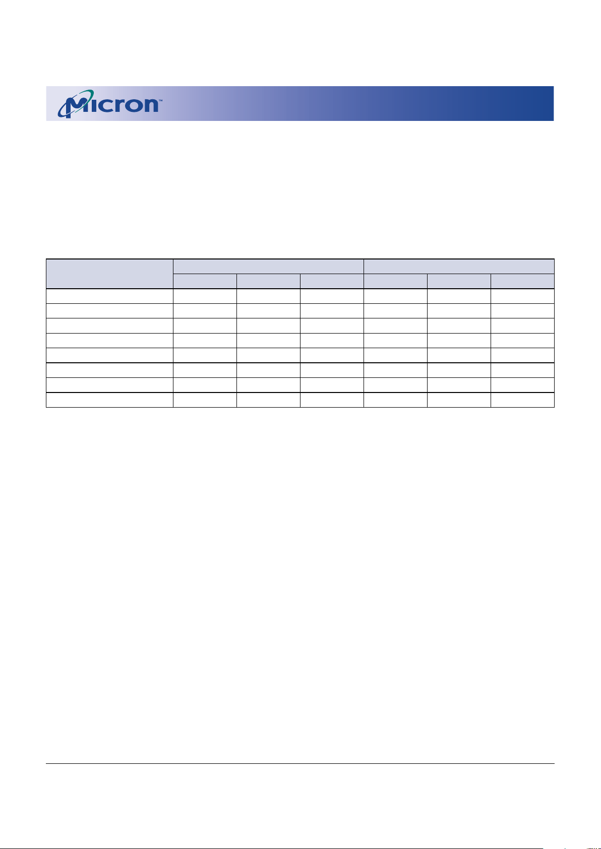
WORD WRITE AND ERASE DURATION CHARACTERISTICS
2.7V–3.3V Vcc
2.7V–3.3V VPP 5V VPP
PARAMETER TYP MAX TYP MAX UNITS NOTES
Boot/parameter BLOCK ERASE time 0.5 4 – – s 4, 5
Main BLOCK ERASE time 1.0 5 – – s 4, 5
Boot/parameter BLOCK WRITE time 0.1 – 0.1 – s 5, 6, 7
Main BLOCK WRITE time 0.3 – 0.3 – s 5, 6, 7
Program/erase suspend latency 1 3 1 3 µs
NOTE: 1. Absolute WRITE/ERASE protection when VPP £ VPPLK.
2. 5V VPP is allowable for production programming only, not erasing. Write timings are identical to 2.7V–3.3V VPP
operation, and 5V VPP programming current is not greater than IPP4.
3. Parameter is specified when device is not accessed. Actual current draw will be IPP6 plus current of operation being
executed while the device is in suspend mode.
4. The 5V VPP is for programming only, not erasing.
5. Typical values measured at TA = +25°C.
6. Assumes no system overhead.
7. Typical write times tested with checkerboard data pattern.
Page 23

23
1 Meg x 16 Enhanced Boot Block Flash Memory Micron Technology, Inc., reserves the right to change products or specifications without notice.
MT28F160A3_3.p65 – Rev. 3, Pub. 8/01 ©2001, Micron Technology, Inc.
1 MEG x 16
ENHANCED BOOT BLOCK FLASH MEMORY
ADVANCE
SPEED-DEPENDENT WRITE/ERASE AC TIMING CHARACTERISTICS AND
RECOMMENDED AC OPERATING CONDITIONS:
WE# (CE#)-CONTROLLED WRITES
(-40°C £ TA £ +85°C; VCC = 2.7V–3.3V)
AC CHARACTERISTICS -9 -11
PARAMETER SYMBOL MIN MIN UNITS NOTES
WE# (CE#) HIGH pulse width
t
WPH (tCPH) 30 30 ns
WE# (CE#) pulse width
t
WP (tCP) 70 70 ns
Address setup time to WE# (CE#) HIGH
t
AS 70 70 ns
Address hold time from WE# (CE#) HIGH
t
AH 0 0 ns
Data setup time to WE# (CE#) HIGH
t
DS 50 60 ns
Data hold time from WE# (CE#) HIGH
t
DH 0 0 ns
CE# (WE#) setup time to WE# (CE#) LOW
t
CS (tWS) 0 0 ns
CE# (WE#) hold time from WE# (CE#) HIGH
t
CH (tWH) 0 0 ns
VPP setup time to WE# (CE#) HIGH
t
VPS 200 200 ns
RP# HIGH to WE# (CE#) LOW delay
t
RS 600 600 ns
WRITE duration
t
WED1 6 6 µs
Boot BLOCK ERASE duration
t
WED2 0.5 0.5 s
Parameter BLOCK ERASE duration
t
WED3 0.5 0.5 s
Main BLOCK ERASE duration
t
WED4 1 1 s
VPP hold time from status data valid
t
VPH 0 0 ns
WE# (CE#) HIGH to busy status (SR7 = 0)
t
WB 200 200 ns 1, 2
NOTE: 1. Polling status register before tWB is met may falsely indicate WRITE or ERASE completion.
2.tWB = 800ns (MAX).
Page 24

24
1 Meg x 16 Enhanced Boot Block Flash Memory Micron Technology, Inc., reserves the right to change products or specifications without notice.
MT28F160A3_3.p65 – Rev. 3, Pub. 8/01 ©2001, Micron Technology, Inc.
1 MEG x 16
ENHANCED BOOT BLOCK FLASH MEMORY
ADVANCE
WRITE/ERASE CYCLE
WE#-CONTROLLED WRITE/ERASE
CE#
A0-A19
OE#
DQ0-DQ15
DON’T CARE
t
WED1, 2, 3, 4
WE#
RP#
V
IH
V
IL
t
RS
A
IN
V
PP
V
IH
V
IL
t
CH
t
CS
V
PPH
t
AS
t
AH
t
WP
t
WPH
t
DS
t
DH
CMD
in
CMD/
Data-in
CMD
in
WRITE SETUP or
ERASE SETUP
input
WRITE or ERASE
executed, status register
checked for completion
Command for next
operation issued
t
DH
t
WB
t
DS
WRITE or block
address asserted, and
WRITE data or ERASE
CONFIRM
V
IH
V
IL
V
IH
V
IL
V
IH
V
IL
V
IH
V
IL
Note 1
t
AS
t
AH
V
IL
Status
(SR7=1)
Status
(SR7=0)
t
VPS
t
VPH
[Unlock boot blocks]
WP#
V
IH
V
IL
t
VPS 200 200 ns
t
RS 600 600 ns
t
WED1 6 6 µs
t
WED2 0.5 0.5 s
t
WED3 0.5 0.5 s
t
WED4 1 1 s
t
VPH 0 0 ns
tWB2
200 200 ns
TIMING PARAMETERS
-9 -11
SYMBOL MIN MIN UNITS
t
WPH 30 30 ns
t
WP 70 70 ns
t
AS 70 70 ns
t
AH 0 0 ns
t
DS 50 60 ns
t
DH 0 0 ns
t
CS 0 0 ns
t
CH 0 0 ns
-9 -11
SYMBOL MIN MIN UNITS
NOTE: 1. Address inputs are “Don’t Care” but must be held stable.
2.tWB = 800ns (MAX).
Page 25

25
1 Meg x 16 Enhanced Boot Block Flash Memory Micron Technology, Inc., reserves the right to change products or specifications without notice.
MT28F160A3_3.p65 – Rev. 3, Pub. 8/01 ©2001, Micron Technology, Inc.
1 MEG x 16
ENHANCED BOOT BLOCK FLASH MEMORY
ADVANCE
WE#
A0-A19
OE#
DQ0-DQ15
DON’T CARE
t
WED1, 2, 3, 4
CE#
RP#
V
IH
V
IL
t
RS
A
IN
V
PP
V
IH
V
IL
t
WH
t
WS
V
PPH
t
AS
t
AH
t
CP
t
CPH
t
DS
t
DH
CMD
in
CMD/
Data-in
CMD
in
WRITE SETUP or
ERASE SETUP
input
WRITE or ERASE
executed, status register
checked for completion
Command for next
operation issued
t
DH
[Unlock boot blocks]
t
DS
WRITE or block
address asserted, and
WRITE data or ERASE
CONFIRM
V
IH
V
IL
V
IH
V
IL
V
IH
V
IL
Note 1
t
AS
t
AH
V
IL
Status
(SR7=1)
Status
(SR7=0)
t
VPS
t
VPH
WP#
V
IH
V
IL
V
IH
V
IL
t
WB
WRITE/ERASE CYCLE
CE#-CONTROLLED WRITE/ERASE
NOTE: 1. Address inputs are “Don’t Care” but must be held stable.
2.tWB = 800ns (MAX).
t
VPS 200 200 ns
t
RS 600 600 ns
t
WED1 6 6 µs
t
WED2 0.5 0.5 s
t
WED3 0.5 0.5 s
t
WED4 1 1 s
t
VPH 0 0 ns
tWB2
200 200 ns
TIMING PARAMETERS
-9 -11
SYMBOL MIN MIN UNITS
t
CPH 30 30 ns
t
CP 70 70 ns
t
AS 70 70 ns
t
AH 0 0 ns
t
DS 50 60 ns
t
DH 0 0 ns
t
WS 0 0 ns
t
WH 0 0 ns
-9 -11
SYMBOL MIN MIN UNITS
Page 26

26
1 Meg x 16 Enhanced Boot Block Flash Memory Micron Technology, Inc., reserves the right to change products or specifications without notice.
MT28F160A3_3.p65 – Rev. 3, Pub. 8/01 ©2001, Micron Technology, Inc.
1 MEG x 16
ENHANCED BOOT BLOCK FLASH MEMORY
ADVANCE
Table 6
Command State Machine Current/Next States
COMMAND INPUTS (and next state)
Current SR7 Data Read Write Block Erase Prog./ Prog./ Read Clear Identify
State when Array setup erase confirm erase erase SR SR device
Read (FFh) (10h/ setup (D0h) susp. resume (70h) (50h) (90h)
40h) (20h) (B0h) (D0h)
Read Array 1 Array Read Write Erase Read array Read Read Identify
array setup setup status array device
Read 1 Status Read Write Erase Read array Read Read Identify
Status array setup setup status array device
Identify 1 ID Read Write Erase Read array Read Read Identify
Device array setup setup status array device
Write 1 Status Program
Setup
Program Not 0 Status Program Prog. Program
Complete (not complete) susp. (not complete)
status
Program 1 Status Program Program suspend Program Program Program Program Program
Suspend susp. read array susp. susp. suspend
Status read read status read array
array array
Program 1 Array Program Program suspend Program Program Program Program Program
Suspend susp. read array susp. susp. suspend
Read Array read read status read array
array array
Program 1 Status Read Write Erase Read array Read Read Identify
Complete Array setup setup status array device
Erase 1 Status Erase command error Erase Erase Erase Erase command error
Setup
Erase 1 Status Read Write Erase Read array Read Read Identify
Comd. Error array setup setup status array device
Erase Not 0 Status Erase (not complete) Erase Erase (not complete)
Complete susp. to
status
Erase 1 Status Erase Write Erase Erase Erase Erase Erase Erase suspend
Suspend susp. setup susp. susp. susp. read array
Status read read read status
array array array
Erase 1 Array Erase Write Erase Erase Erase Erase Erase Erase suspend
Suspend susp. setup susp. susp. susp. read array
Array read read read status
array array array
Erase 1 Status Read Write Erase
Read array
Read Read Identify
Complete array setup setup status array device
Page 27

27
1 Meg x 16 Enhanced Boot Block Flash Memory Micron Technology, Inc., reserves the right to change products or specifications without notice.
MT28F160A3_3.p65 – Rev. 3, Pub. 8/01 ©2001, Micron Technology, Inc.
1 MEG x 16
ENHANCED BOOT BLOCK FLASH MEMORY
ADVANCE
NOTE: 1. All dimensions in millimeters
MAX
or typical where noted.
MIN
2. Package width and length do not include mold protrusion; allowable mold protrusion is 0.25mm per side.
46-BALL FBGA
3.50 ±.05
3.75
.75 (TYP)
.75
(TYP)
PIN #1 ID
SOLDER BALL MATERIAL: EUTECTIC 63% Sn, 37% Pb
SOLDER BALL PAD: Ø .27mm
MOLD COMPOUND: EPOXY NOVOLAC
SUBSTRATE: PLASTIC LAMINATE
PIN #1 ID
8.00 ±.10
1.20 MAX
4.00 ±.05
2.625 ±.05
5.25
.80 ±.075
.10
A
A
.35
+.05
-.10
(TYP)
Ø
1.875 ±.05
7.00 ±.10
8000 S. Federal Way, P.O. Box 6, Boise, ID 83707-0006, Tel: 208-368-3900
E-mail: prodmktg@micron.com, Internet: http://www.micron.com, Customer Comment Line: 800-932-4992
Micron is a registered trademark and the Micron logo and M logo are trademarks of Micron Technology, Inc.
DATA SHEET DESIGNATION
Advance: This data sheet contains initial descriptions of products still under development.
Page 28

28
1 Meg x 16 Enhanced Boot Block Flash Memory Micron Technology, Inc., reserves the right to change products or specifications without notice.
MT28F160A3_3.p65 – Rev. 3, Pub. 8/01 ©2001, Micron Technology, Inc.
1 MEG x 16
ENHANCED BOOT BLOCK FLASH MEMORY
ADVANCE
REVISION HISTORY
Rev. 3 .................................................................................................................................................................................... 8/01
• Added tWB maximum specification
• Corrected WRITE/ERASE Cycle timing diagram (CE-controlled)
Rev. B ................................................................................................................................................................................... 5/01
• Changed ICC1 MAX from 30 mA to 20 mA
Original document ............................................................................................................................................................. 6/00
 Loading...