

Datasheet MSQC6910C, MSQC6940C, MSQC6140C, MSQC6440C, MSQC6110C Datasheet (Fairchild Semiconductor)
Page 1
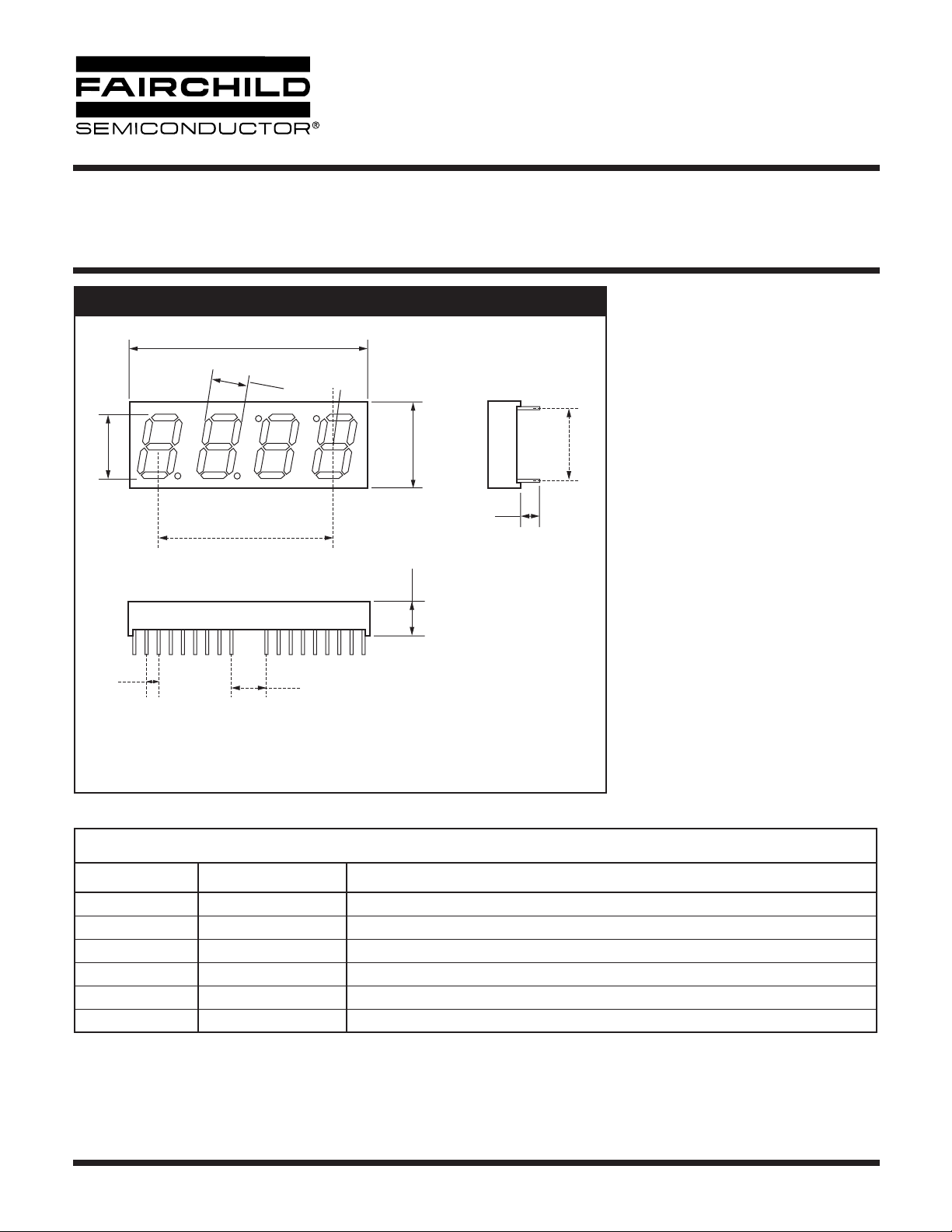
14mm (0.56 inch) Four Digit
CLOCK STICK DISPLAY
Bright Red MSQC6110C, MSQC6140C
High Efficiency Red MSQC6910C, MSQC6940C
Green MSQC6410C, MSQC6440C
PACKAGE DIMENSIONS
38.10 (1.500)
7.90
(0.311)
14.22
(0.560)
38.10
(1.500)
MSQCX6XX0W YWW LL H
2.54
(0.100)
Notes:
• Dimensions are in mm (inches)
• Tolerances are ±0.25mm (0.010") unless otherwise stated.
5.08
(0.200)
10°
17.10
(0.673)
80.00
(0.315)
NOTES:
5.00
(0.197)
15.24
(0.600)
Features
• Bright Bold Segments
• Common Anode/Cathode
• Low Power Consumption
• Low Current Capability
• Neutral Segments
• Grey Face
• Epoxy Encapsulated PCB
• High Performance
• High Reliability
Applications
• Appliances
• Automotive
• Instrumentation
• Process Control
MODELS AVAILABLE
Part Number Color Description
MSQC6110C Bright Red Four Digit, Clock Display, Common Anode
MSQC6140C Bright Red Four Digit, Clock Display, Common Cathode
MSQC6410C Green Four Digit, Clock Display, Common Anode
MSQC6440C Green Four Digit, Clock Display, Common Cathode
MSQC6910C High Efficiency Red Four Digit, Clock Display, Common Anode
MSQC6940C High Efficiency Red Four Digit, Clock Display, Common Cathode
© 2002 Fairchild Semiconductor Corporation
Page 1 of 7
7/3/02
Page 2
)
)
)
)
High Efficiency Red MSQC6910C, MSQC6940C
ABSOLUTE MAXIMUM RATINGS
14mm (0.56 inch) Four Digit
CLOCK STICK DISPLAY
Bright Red MSQC6110C, MSQC6140C
Green MSQC6410C, MSQC6440C
(1)
(T
= 25°C, unless otherwise specified)
A
Part Number
Parameter
Continuous Forward Current
(each segment)
Peak Forward Current
(F = 10KHz, D/F = 1/10)
Power Dissipation (P
*Derate Linearly from 25°C
Reverse Voltage per Die
Operating and Storage Temperature Range
Lead soldering time (1/16 inch from standoffs)
ELECTRO-OPTICAL CHARACTERISTICS
Part Number
Parameter
Luminous intensity
Minimum (Standard Current) 300 800 900 µcd
Typical (Standard Current) 700 2000 2200 µcd
Minimum (Low Current) Not Available
Typical (Low Current) Not Available
Forward Voltage (V
Typical (Standard Current) 2.10 2.10 2.00 V
Maximum (Standard Current) 2.60 2.80 2.80 V
Typical (Low Current) Not Available
Maximum (Low Current) Not Available
Peak Wavelength
Dominant Wavelength
Spectral Line 1/2 Width
Reverse B
(3)
. Voltage (V
D
(1)
MSQC6110C
MSQC6140C
(2)
(I
V
F
697 565 635 nm
700 569 627 nm
90 30 45 nm
R
5 5 5 V
MSQC6110C
MSQC6140C
15 25 25 mA
60 100 90 mA
40 75 70 mW
0.24 0.68 0.63 mW
(T
= 25°C, unless otherwise specified)
A
MSQC6410C
MSQC6440C
MSQC6410C
MSQC6440C
MSQC6910C
MSQC6910C
MSQC6910C
MSQC6940C
5 Volts
-25°C to +105°C
5 seconds @ 230°C
Units
Units
Test
Condition
I
= 20mA
F
I
= 20mA
F
I
= 20mA
F
I
= 20mA
F
I
= 20mA
F
I
= 20mA
F
I
= 10mA
F
I
= 100µA
R
NOTES:
(1) Data per individual LED element
(2) Luminous intensity (µcd) = average light output per segment
(3) B = breakdown
© 2002 Fairchild Semiconductor Corporation
Page 2 of 7
7/3/02
Page 3
14mm (0.56 inch) Four Digit
CLOCK STICK DISPLAY
Bright Red MSQC6110C, MSQC6140C
High Efficiency Red MSQC6910C, MSQC6940C
Green MSQC6410C, MSQC6440C
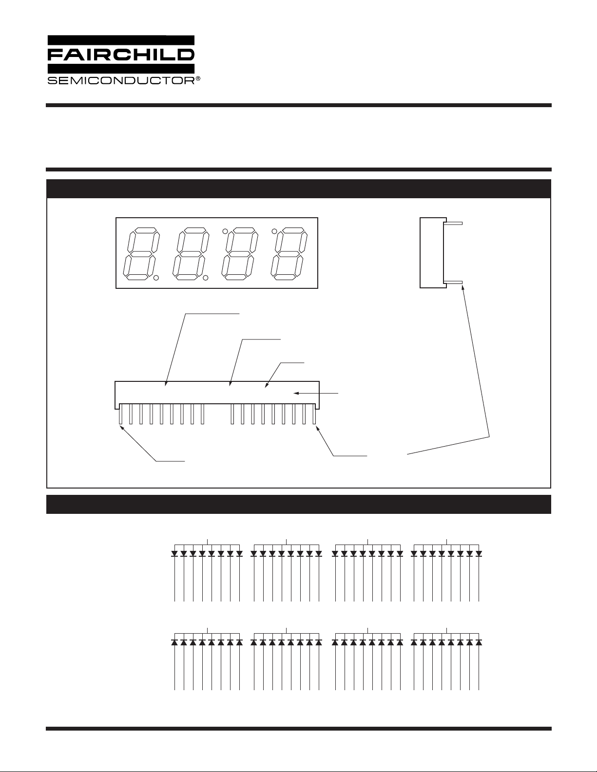
PIN ORIENTATION, SEGMENT IDENTIFICATION, AND PRODUCT MARKING
Dp3
E
F
Digit 1
A
B
G
C
D
Dp1 Dp2
Digit 2 Digit 3 Digit 4
MSQC6XX0C YWW LL H
Pin #1
Dp4
Part Number
Date Code
Light Category
Hue (Wavelength)
Yellow and Green Only
Pin #18
SCHEMATICS
MSQC6X10C
Common Anode
ABCDEFGDp
34 33 3 2 1 36 35
MSQC6X40C
Common Cathode
ABCDEFGDp
34 33 3 2 1 36 35
© 2002 Fairchild Semiconductor Corporation
32
ABCDEFGDp
4
29 28 8 6 5 30 7 9
32
ABCDEFGDp
4
29 28 8 6 5 30 7 9
31 13
ABCDEFGDp
11 10 28 24 23 12 25 27
31 13 14
ABCDEFGDp
24 23 12 11 10 26 25 27
ABCDEFGDp
16 15 21 20 19 18 17 22
ABCDEFGDp
20 19 18 16 15 21 17 22
Page 3 of 7
14
7/3/02
Page 4

14mm (0.56 inch) Four Digit
CLOCK STICK DISPLAY
Bright Red MSQC6110C, MSQC6140C
High Efficiency Red MSQC6910C, MSQC6940C
Green MSQC6410C, MSQC6440C
GRAPHICAL DATA Bright Red
50
40
=mA)IDCMAX-Maximum DC Current - mA
F
30
20
10
Forward Current (I
0
1.2 1.6 2.0 2.4 2.8
Forward Voltage (V
Fig. 1 Forward Current vs. Forward Voltage
2.50
2.25
2.00
1.50
1.25
1.00
0.50
To Value AT = 20mA
0.25
Luminous Intensity Relative
0
0 102030 4050
- Forward Current - mA
I
Fig. 3 Relative Luminous Intensity vs. Forward Current
35
F
F
(T
= 25°C, unless otherwise specified)
A
120
100
80
60
40
Relative Output-%
20
0
600 640 680 720 760 800
) - Volts
2
1.5
Relative Intensity
1
10 20 40 DC
1000
Wavelength (λ)-nm
Fig. 2 Spectral Response
Duty Cycle % Per Segment
(Average I
Fig. 5 Luminous Intensity vs. Duty Cycle
= 10mA)
F
30
25
20
15
10
5
0
-40 -20 0 20 40 60 80 100
T
AMBIENT TEMPERATURE °C
Fig. 4 Maximum Allowable DC Current per Segment vs.
© 2002 Fairchild Semiconductor Corporation
A
a Function of Ambient Temperature
Page 4 of 7
500
200
- mA
P
100
75
Peak I
50
25
10
1 3 5 10 20 50 100
Fig. 6 Max Peak Current vs. Duty Cycle %
Duty Cycle %
(Refresh Rate f=1 KHz)
7/3/02
Page 5

14mm (0.56 inch) Four Digit
CLOCK STICK DISPLAY
Bright Red MSQC6110C, MSQC6140C
High Efficiency Red MSQC6910C, MSQC6940C
Green MSQC6410C, MSQC6440C
GRAPHICAL DATA Green
50
40
=mA)IDCMAX-Maximum DC Current - mA
F
30
20
10
Forward Current (I
0
1.2 1.6 2.0 2.4 2.8
Forward Voltage (V
Fig. 1 Forward Current vs. Forward Voltage
2.50
2.25
2.00
1.50
1.25
1.00
0.50
To Value AT = 20mA
0.25
Luminous Intensity Relative
0
0 102030 4050
- Forward Current - mA
I
Fig. 3 Relative Luminous Intensity vs. Forward Current
35
F
(T
= 25°C, unless otherwise specified)
A
120
100
80
60
40
Relative Output-%
20
0
) - Volts
F
2
1.5
Relative Intensity
1
1000
520 560 600 640 680 720
Wavelength (λ)-nm
Fig. 2 Spectral Response
10 20 40 DC
Duty Cycle % Per Segment
Fig. 5 Luminous Intensity vs. Duty Cycle
(Average I
= 10mA)
F
30
25
20
15
10
5
0
-40 -20 0 20 40 60 80 100
AMBIENT TEMPERATURE °C
T
Fig. 4 Maximum Allowable DC Current per Segment vs.
© 2002 Fairchild Semiconductor Corporation
A
a Function of Ambient Temperature
Page 5 of 7
500
200
- mA
P
100
75
Peak I
50
25
10
1 3 5 10 20 50 100
Fig. 6 Max Peak Current vs. Duty Cycle %
Duty Cycle %
(Refresh Rate f=1 KHz)
7/3/02
Page 6

14mm (0.56 inch) Four Digit
CLOCK STICK DISPLAY
Bright Red MSQC6110C, MSQC6140C
High Efficiency Red MSQC6910C, MSQC6940C
Green MSQC6410C, MSQC6440C
GRAPHICAL DATA High Efficiency Red
50
40
=mA)IDCMAX-Maximum DC Current - mA
F
30
20
10
Forward Current (I
0
1.2 1.6 2.0 2.4 2.8
Forward Voltage (V
Fig. 1 Forward Current vs. Forward Voltage
2.50
2.25
2.00
1.50
1.25
1.00
0.50
To Value AT = 20mA
0.25
Luminous Intensity Relative
0
0 102030 4050
- Forward Current - mA
I
Fig. 3 Relative Luminous Intensity vs. Forward Current
F
) - Volts
F
(T
= 25°C, unless otherwise specified)
A
120
100
80
60
40
Relative Output-%
20
0
520 560 600 640 680 720
Wavelength (λ)-nm
Fig. 2 Spectral Response
2
1.5
Relative Intensity
1
10 20 40 DC
Duty Cycle % Per Segment
Fig. 5 Luminous Intensity vs. Duty Cycle
(Average I
= 10mA)
F
35
30
25
20
15
10
5
0
-40 -20 0 20 40 60 80 100
AMBIENT TEMPERATURE °C
T
Fig. 4 Maximum Allowable DC Current per Segment vs.
© 2002 Fairchild Semiconductor Corporation
A
a Function of Ambient Temperature
Page 6 of 7
1000
500
200
- mA
P
100
75
Peak I
50
25
10
1 3 5 10 20 50 100
Fig. 6 Max Peak Current vs. Duty Cycle %
Duty Cycle %
(Refresh Rate f=1 KHz)
7/3/02
Page 7

14mm (0.56 inch) Four Digit
CLOCK STICK DISPLAY
Bright Red MSQC6110C, MSQC6140C
High Efficiency Red MSQC6910C, MSQC6940C
Green MSQC6410C, MSQC6440C
DISCLAIMER
FAIRCHILD SEMICONDUCTOR RESERVES THE RIGHT TO MAKE CHANGES WITHOUT FURTHER NOTICE TO
ANY PRODUCTS HEREIN TO IMPROVE RELIABILITY, FUNCTION OR DESIGN. FAIRCHILD DOES NOT ASSUME
ANY LIABILITY ARISING OUT OF THE APPLICATION OR USE OF ANY PRODUCT OR CIRCUIT DESCRIBED HEREIN;
NEITHER DOES IT CONVEY ANY LICENSE UNDER ITS PATENT RIGHTS, NOR THE RIGHTS OF OTHERS.
LIFE SUPPORT POLICY
FAIRCHILD’S PRODUCTS ARE NOT AUTHORIZED FOR USE AS CRITICAL COMPONENTS IN LIFE SUPPORT DEVICES
OR SYSTEMS WITHOUT THE EXPRESS WRITTEN APPROVAL OF THE PRESIDENT OF FAIRCHILD SEMICONDUCTOR
CORPORATION. As used herein:
1. Life support devices or systems are devices or systems
which, (a) are intended for surgical implant into the body, or
(b) support or sustain life, and (c) whose failure to perform
when properly used in accordance with instructions for use
provided in the labeling, can be reasonably expected to
result in a significant injury of the user.
2. A critical component in any component of a life support
device or system whose failure to perform can be
reasonably expected to cause the failure of the life support
device or system, or to affect its safety or effectiveness.
© 2002 Fairchild Semiconductor Corporation
Page 7 of 7
7/3/02
 Loading...