

Page 1
ISO-9001 CERTIFIED BY DSCC
QUAD N-CHANNEL
MOSFET POWER MODULE
M.S.KENNEDY CORP.
4707 Dey Road Liverpool, N.Y. 13088
FEATURES:
• Pin Compatible with MPM3013
• QUAD Independent N - Channel MOSFETS
• Isolated Package for Direct Heat Sinking, Excellent Thermal Conductivity
• Avalanche Rated Devices
• 55 Volt, 25 Amp Rated
• Low RDS (ON) - 0.022Ω For Each Die
DESCRIPTION:
The MSK 3013 is a QUAD N-Channel power circuit packaged in a space efficient isolated ceramic tab power SIP
package. The MSK 3013 consists of four totally isolated N-Channel MOSFETs. The MSK 3013 uses M.S.Kennedy's
proven power hybrid technology to bring a cost effective high performance circuit for use in today's sophisticated
servo motor and disk drive systems. The MSK 3013 is a replacement for the MPM3013 with only minor differences
in specifications.
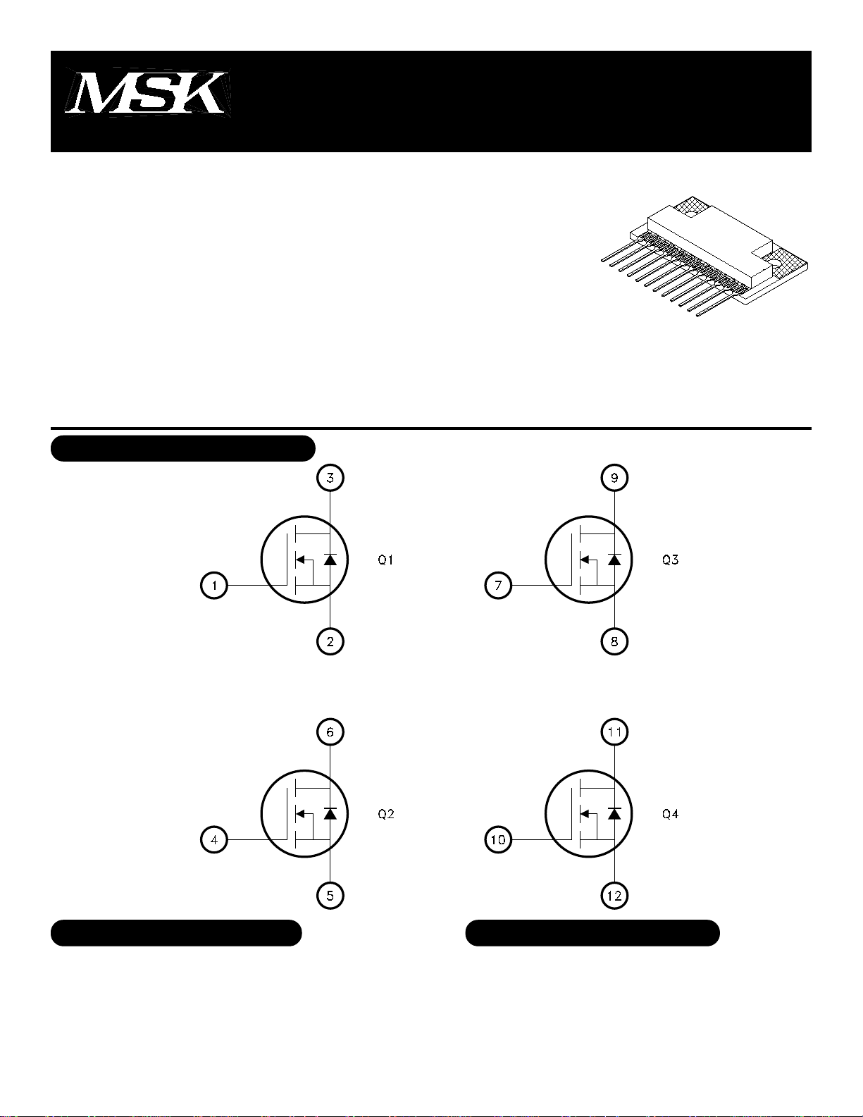
EQUIVALENT SCHEMATIC
3013
(315) 701-6751
TYPICAL APPLICATIONS
• Stepper Motor Servo Control
• Disk Drive Head Control
• X-Y Table Control
• Az-El Antenna Control
• Various Switching Applications
PIN-OUT INFORMATION
1 Q1 Gate 7 Q3 Gate
2 Q1 Source 8 Q3 Source
3 Q1 Drain 9 Q3 Drain
4 Q2 Gate 10 Q4 Gate
5 Q2 Source 11 Q4 Drain
6 Q2 Drain 12 Q4 Source
1
Rev. B 7/00
Page 2
ABSOLUTE MAXIMUM RATINGS
VDSS Drain to Source Voltage . . .55V MAX
VDGDR Drain to Gate Voltage
(RGS=1MΩ)......... 55V MAX
VGS Gate to Source Voltage
(Continuous)........ ±20V MAX
TJ Junction Temperature. . . ........+175°C MAX
TST Storage Temperature. . . ......-55°C TO +150°C
TC Case Operating Temperature Range . .-55°C TO 125°C
TLD Lead Temperature Range
(10 Seconds) . . . . . . ..........300°C MAX
ID Continuous Current ..... 25A MAX
IDM Pulsed Current ....... 49A MAX
RTH-JC Thermal Resistance
(Junction to Case)...... 0.3°C/W
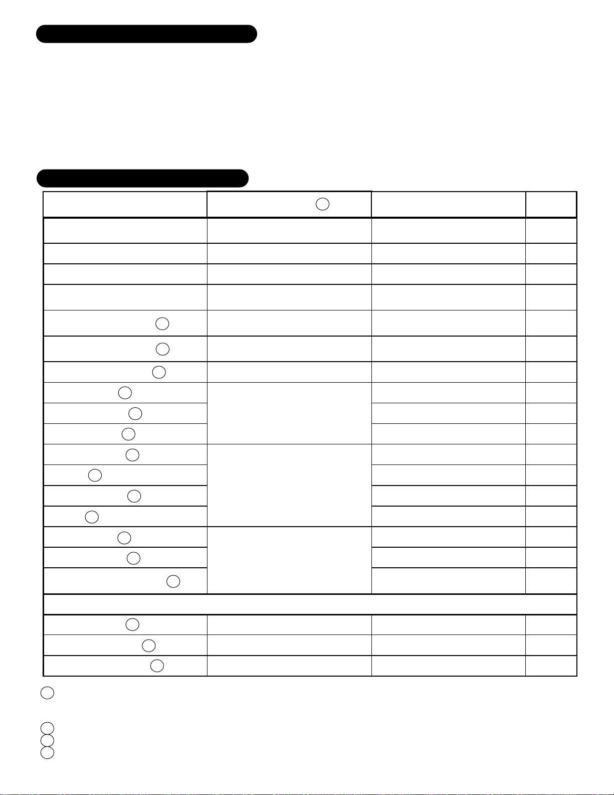
ELECTRICAL SPECIFICATIONS
Parameter
Drain-Source Breakdown Voltage VGS = 0 ID = 0.25 mA 55 - - V
Drain-Source Leakage Current VDS = 55V VGS = 0V - - 25 µA
Gate-Source Leakage Current VGS = ±20V VDS = 0 - - ±100 nA
Gate-Source Threshold Voltage VDS = VGS ID = 250 µA 2 - 4 V
Drain-Source on Resistance 2 VGS = 10V ID = 25A - 0.033 0.040
Drain-Source on Resistance 3 VGS = 10V ID = 25A - - 0.022
Test Conditions 4
Min. Typ. Max.
MSK 3013
Units
Ω
Ω
Forward Transconductance 1 VDS = 25V ID = 25A 17 - - S
Total Gate Charge 1 ID = 25A - - 65 nC
Gate-Source Charge 1 VDS = 28V - - 12 nC
Gate-Drain Charge 1 VGS = 10V - - 27 nC
Turn-On Delay Time 1 VDD = 28V - 7.3 - nS
Rise Time 1 ID = 25A - 69 - nS
Turn-Off Delay Time 1 RG = 12 - 47 - nS
Fall Time 1 RD = 1.1 - 60 - nS
Input Capacitance 1 VGS = 0V - 1300 - pF
Output Capacitance 1 VDS = 25V - 410 - pF
Reverse Transfer Capacitance 1 f = 1 MHz - 150 - pF
BODY DIODE
Forward on Voltage 1 IS = 25A VGS = 0V - 1.3 1.75 V
Reverse Recovery Time 1 IS = 25A di/dt = 100A/µS - 65 98 nS
Ω
Reverse Recovery Charge 1 IS = 25A di/dt = 100A/µS - 160 240 µC
NOTES:
1 This parameter is guaranteed by design but need not be tested. Typical parameters are representative of
actual
device performance but are for reference only.
2 Resistance as seen at package pins.
3 Resistance for die only; use for thermal calculations.
4TA=25°C unless otherwise specified. Parameters apply to each transistor in the module.
2
Rev. B 7/00
Page 3
APPLICATION NOTES
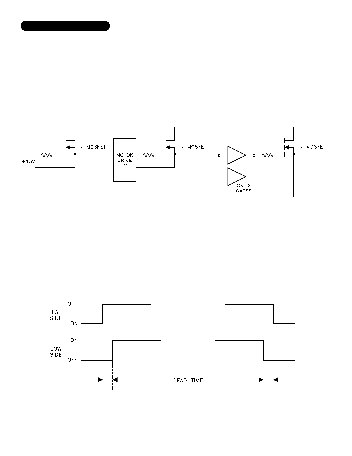
N-CHANNEL GATES
For driving the N-Channel gates, it is important to keep in mind that it is essentially like driving a capacitance to a sufficient
voltage to get the channel fully on. Driving the gates to +15 volts with respect to their sources assures that the transistors are on.
This will keep the dissipation down to a minimum level [RDS(ON) specified in the data sheet]. How quickly the gate gets turned ON
and OFF will determine the dissipation of the transistor while it is transitioning from OFF to ON, and vice-versa. Turning the gate
ON and OFF too slow will cause excessive dissipation, while turning it ON and OFF too fast will cause excessive switching noise
in the system. It is important to have as low a driving impedance as practical for the size of the transistor. Many motor drive IC's
have sufficient gate drive capability for the MSK 3013. If not, paralleled CMOS standard gates will usually be sufficient. A series
resistor in the gate circuit slows it down, but also suppresses any ringing caused by stray inductances in the MOSFET circuit. The
selection of the resistor is determined by how fast the MOSFET wants to be switched. See Figure 1 for circuit details.
Figure 1
BRIDGE DRIVE CONSIDERATIONS
It is important that the logic used to turn ON and OFF the various transistors allow sufficient "dead time" between a high side
transistor and its low side transistor to make sure that at no time are they both ON. When they are, this is called "shoot-through",
and it places a momentary short across the power supply. This overly stresses the transistors and causes excessive noise as well.
See Figure 3.
Figure 2
This deadtime should allow for the turn on and turn off time of the transistors, especially when slowing them down with gate
resistors. This situation will be present when switching motor direction, or when sophisticated timing schemes are used for servo
systems such as locked antiphase PWM'ing for high bandwidth operation.
3
Rev. B 7/00
Page 4
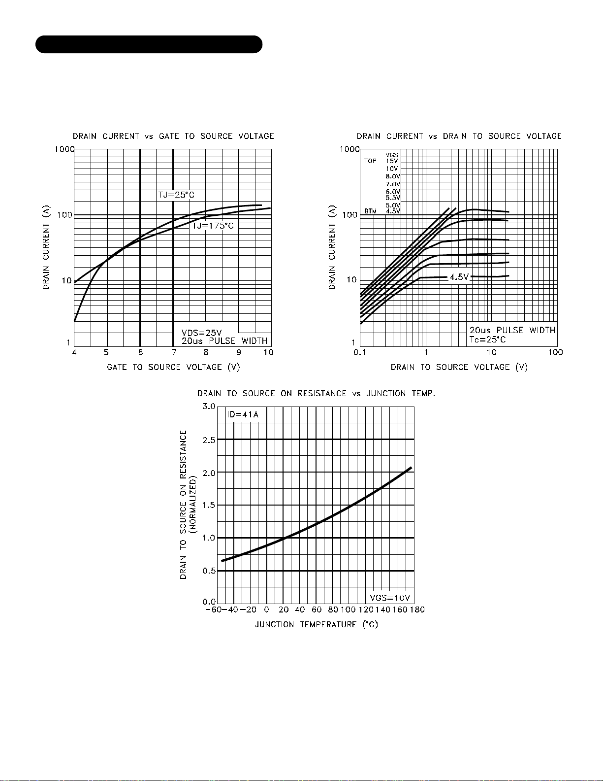
TYPICAL PERFORMANCE CURVES
4
Rev. B 7/00
Page 5
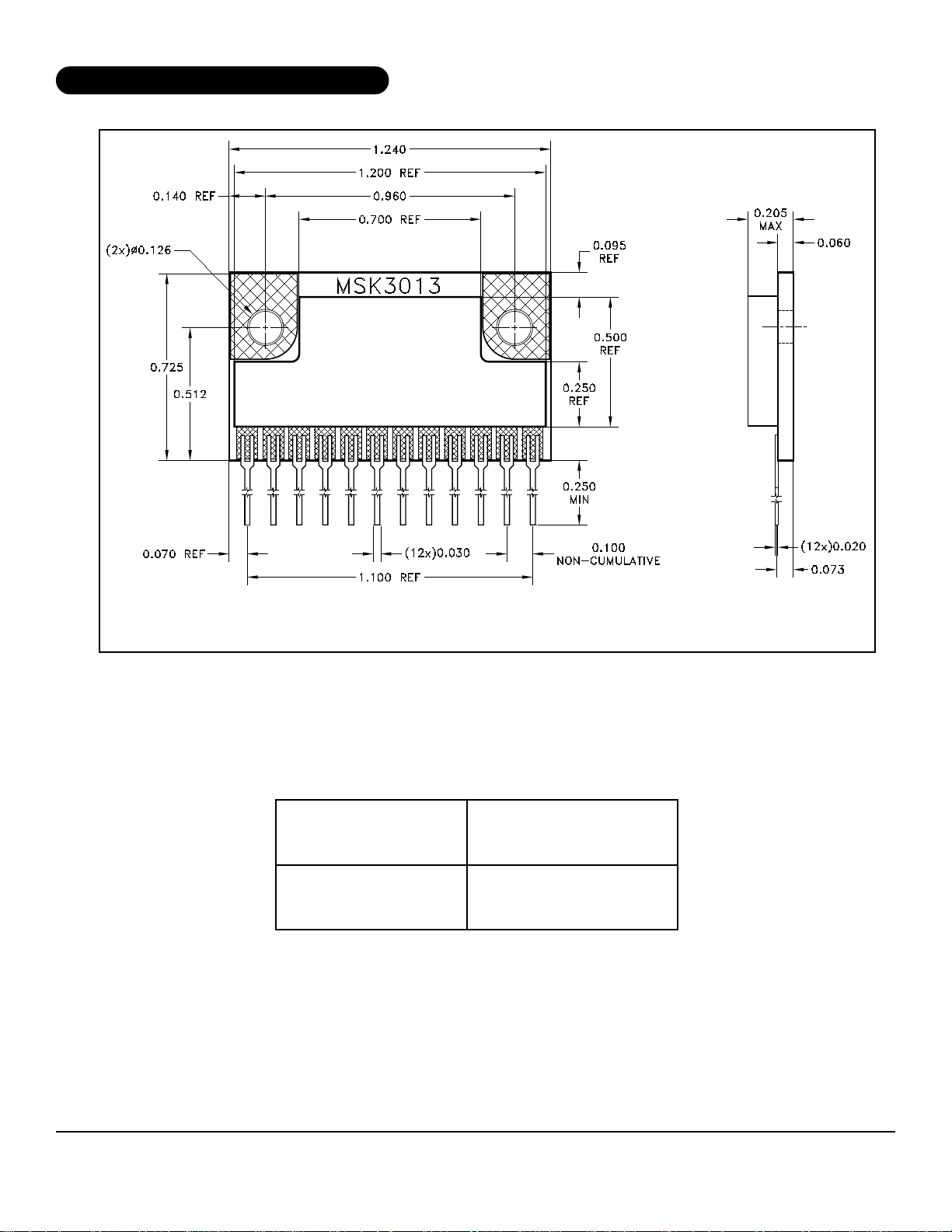
MECHANICAL SPECIFICATIONS
TORQUE SPECIFICATION 3 TO 5 IN/LBS. TEFLON SCREWS OR WASHERS ARE RECOMMENDED.
ALL DIMENSIONS ARE ±0.010 INCHES UNLESS OTHERWISE LABELED.
ORDERING INFORMATION
PART
NUMBER
MSK 3013
M.S. Kennedy Corp.
4707 Dey Road, Liverpool, New York 13088
Phone (315) 701-6751
FAX (315) 701-6752
www.mskenndy.com
SCREENING LEVEL
Industrial
The information contained herein is believed to be accurate at the time of printing. MSK reserves the right to make
changes to its products or specifications without notice, however, and assumes no liability for the use of its products.
5
Rev. B 7/00
 Loading...