

Page 1

E2B0018-27-Y2
¡ Semiconductor
This version: Nov. 1997
Previous version: Mar. 1996
MSC5301B-02¡ Semiconductor
MSC5301B-02
LCD COMMON/SEGMENT DRIVER WITH RAM
GENERAL DESCRIPTION
The MSC5301B-02 is an LCD driver LSI with a built-in RAM. The device's bit mapping method
offers greater flexibility in which each bit of the display RAM controls each section on the LCD
panel. It can form a graphic display system of 64 x 8 dots in one chip. In addition, the display can
be expanded by using the additional LSIs.
FEATURES
• LCD driving voltage range : 6 to 16V
• Operating power supply voltage range : 5V ±10%
• Display duty : 1/8 (1/4 bias)
• Common output : 8 outputs
• Segment output : 64 outputs
• RAM capacity : 8 x 64 = 512 bits
• Serial transfer clock frequency (f
• Multichip configuration available
• Blanking available
• Built-in RC oscillation circuit
• Package:
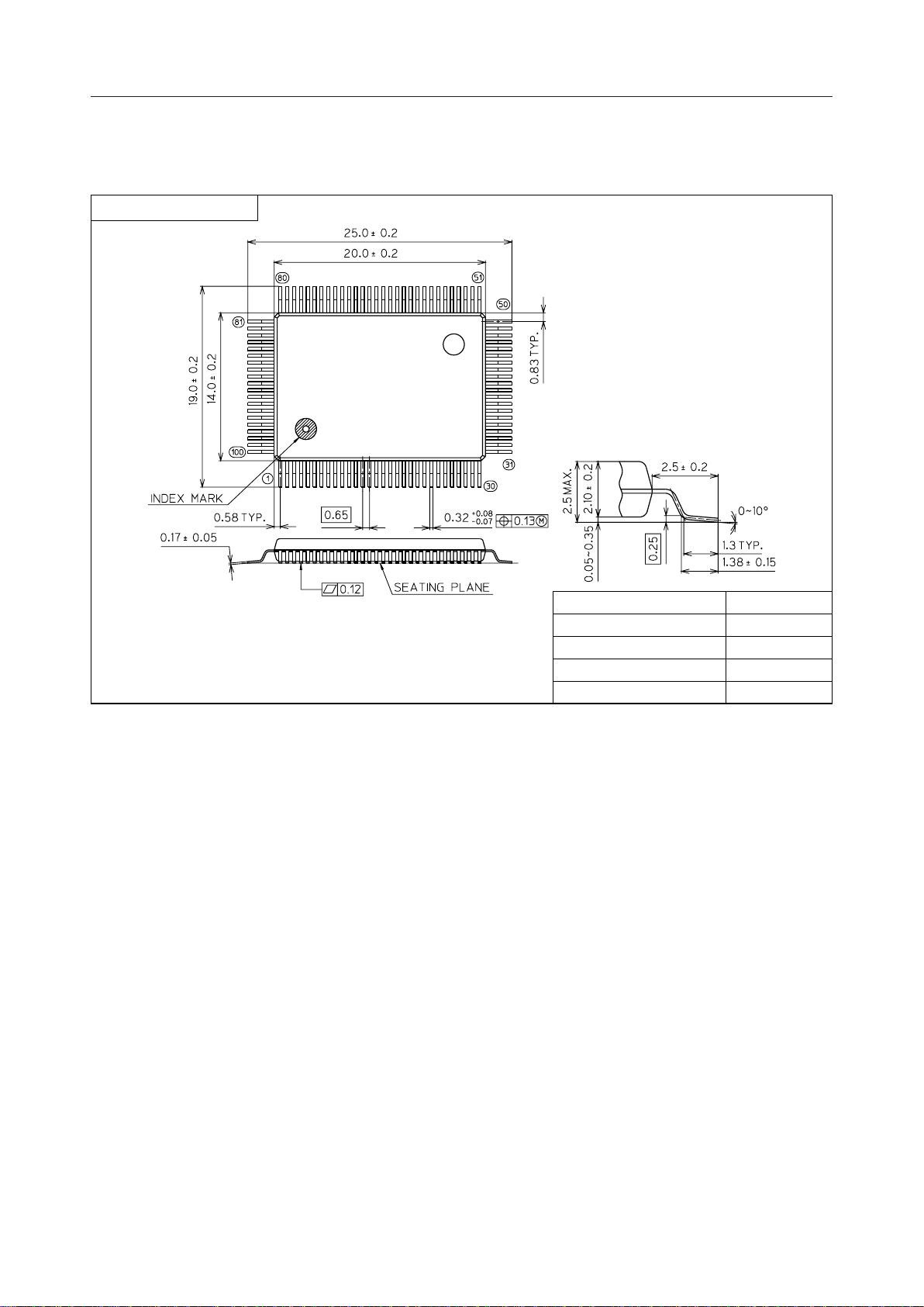
100-pin plastic QFP (QFP100-P-1420-0.65-BK) (Product name: MSC5310B-02GS-BK)
) : 500 kHz Max.
SCK
1/15
Page 2
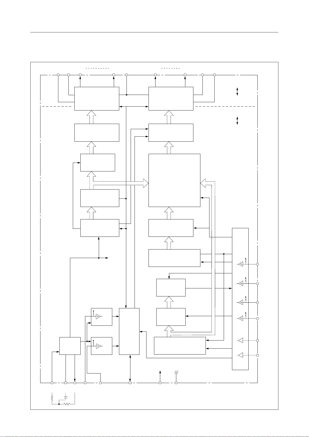
BLOCK DIAGRAM
MSC5301B-02¡ Semiconductor
V4V1C0 C7 V
8-DOT COM DRV
(4-LEVEL DRV)
3-8 DECODER 64-BIT LATCH
3-BIT LATCH
READ (3-BIT)
ADDRESS COUNTER
DSP
S63 S0 V2V
64-DOT SEG DRV
(4-LEVEL DRV)
RAM
RA
RA
RA
2
1
0
64 x 8 = 512 bits
WA
WA
WA
2
1
0
WE
3
V
DSP
GND
V
CC
GND
OSC
TIMING
GENERATOR
BLK
CTL
POR
CTL
64-BIT LATCH
INPUT
CTL
f
64-BIT SHIFT REGISTER
LATCH
CHIP CTL
A / D
SI
6-BIT LATCH
SCK
FRAM
IN/OUT
CS0
8-BIT SHIFT REGISTER
CS1
OS1 OS2 f BLK POR FRAM V
CC
GND
2/15
Page 3
MSC5301B-02¡ Semiconductor
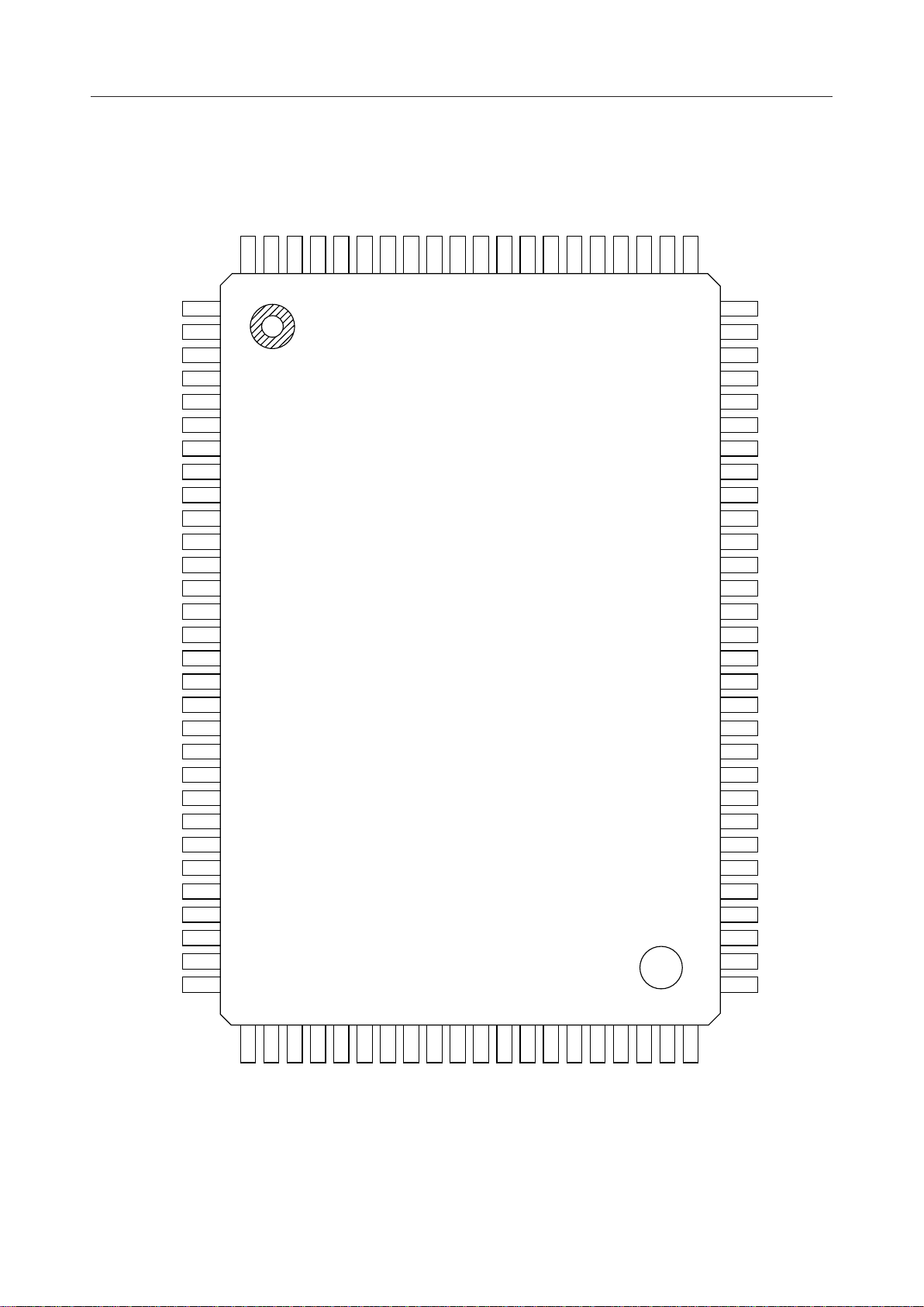
PIN CONFIGURATION
S52
S51
999897969594939291908988878685
100
S53
1
S54
2
S55
3
S56
4
S57
5
S58
6
S59
7
S60
8
S61
9
S62
10
S63
11
NC
12
C0
13
NC
14
C1
15
NC
16
C2
17
NC
18
C3
19
NC
20
C4
21
NC
22
C5
23
NC
24
C6
25
NC
26
C7
27
V
28
4
V
29
1
CS0
30
(TOP VIEW)
S50
S49
S48
S47
S46
S45NCS44
S43
S42
S41
S40
S39
S38
S37
84
S36
S35
S34
838281
80
79
78
77
76
75
74
73
72
71
70
69
68
67
66
65
64
63
62
61
60
59
58
57
56
55
54
53
52
51
S33
S32
S31
S30
S29
S28
S27
S26
S25
S24
S23
S22
S21
S20
S19
S18
S17
S16
S15
S14
S13
S12
S11
S10
S9
S8
S7
S6
S5
S4
3132333435363738394041
f
OS2
CS1
A/D
LATCH
SI
SCK
POR
BLK
FRM
OS1
NC: No connection
100-Pin Plastic QFP
4243444546
CC
V
GND
DSP
V
V2V
47
3
S0S1S2
48
49
50
S3
3/15
Page 4
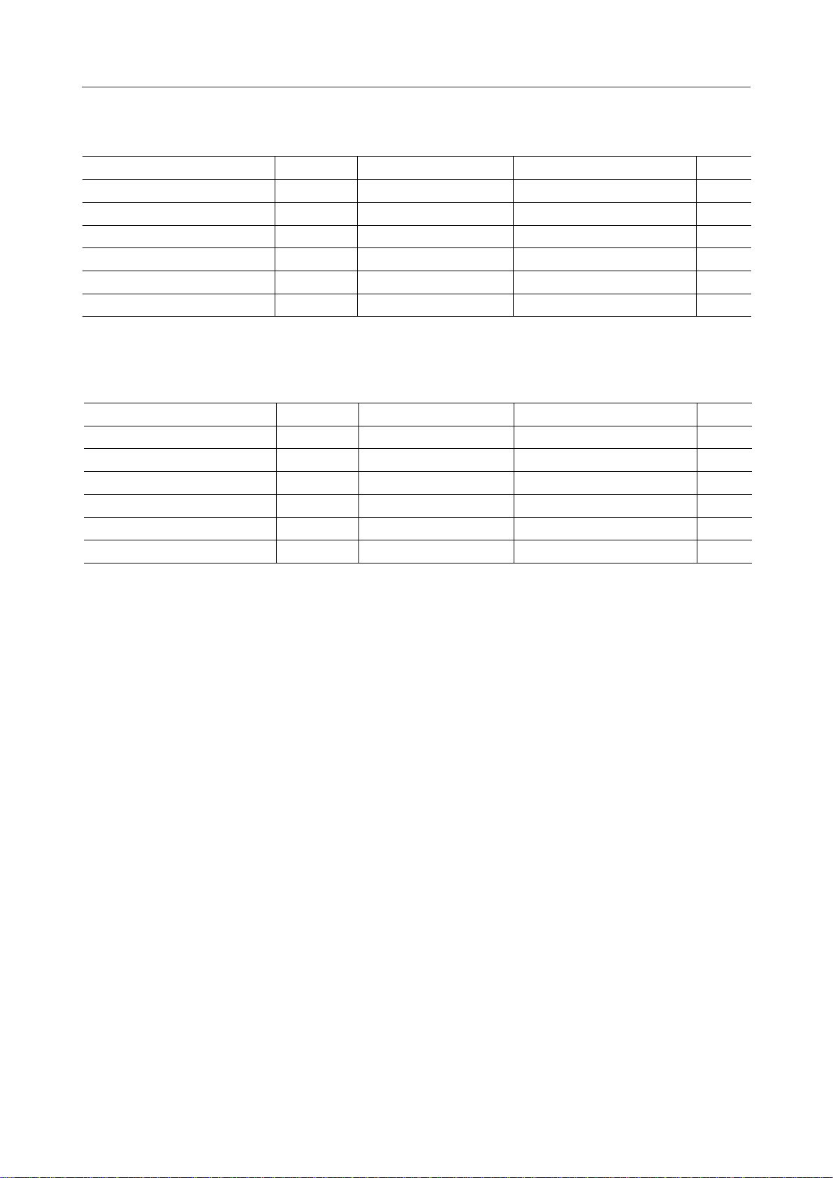
ABSOLUTE MAXIMUM RATINGS
MSC5301B-02¡ Semiconductor
Parameter Condition
Power Supply Voltage
Power Supply Voltage Ta = 25°CV
Input Voltage Ta = 25°CV
Input Voltage Ta = 25°CV
Power Dissipation Ta = 85°CP
Storage Temperature —T
*1 V
DSP>V1>V2≥V3>V4
Symbol Rating Unit
CC
DSP
IN
INDP
D
STG
Ta = 25°CV
>GND
RECOMMENDED OPERATING CONDITIONS
Parameter Condition
Power Supply Voltage
Power Supply Voltage GND = 0VV
Operating Temperature —T
Shift Frequency —f
Oscillation Frequency —f
Frame Frequency —f
Symbol Range Unit
CC
DSP
op
SCK
f
FR
GND = 0VV
–0.3 to +6.5 V
–0.3 to +18.0 V
–0.3V £ V
–0.3 £ V
£ VCC+0.3 V
IN
£ V
INDP
+0.3 V
DSP
275 mW
–55 to +125 °C
4.5 to 5.5 V
6.0 to 16.0 V
–40 to +85 °C
25 to 500 kHz
1.92 to 8.0 kHz
60 to 250 Hz
*1
*1
*1 V
DSP>V1>V2≥V3>V4
>GND
4/15
Page 5
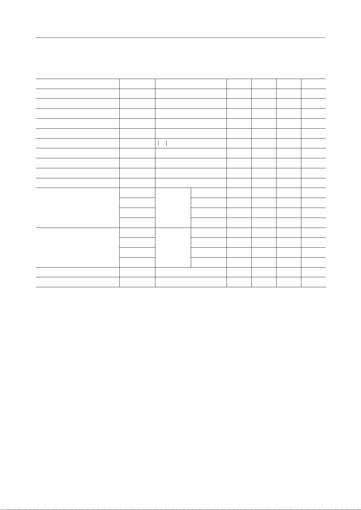
ELECTRICAL CHARACTERISTICS
DC Characteristics
Parameter Symbol Condition Min. Typ. Max. Unit
V
IH
V
IL
V
HS1
V
HS2
R
PU
V
PH
I
IH
I
IL
V
OH
V
OL
V
DP
Output Voltage
Output Voltage
V
V
V
V
V
V
V
I
I
DSP
1
4
SS
DP
2
3
SS
CC
= 0V
V
I
< 1mA
I
IN
= 5.5V, VIH = 5.5V
V
CC
= 5.5V, VIL = 0V
V
CC
= –0.4mA
I
O
= 1.6mA
I
O
= 10V
V
DSP
*5
= 10V
V
DSP
*6
= 5.0V
V
CC
= 5.0V
V
CC
I = –10mA
I = ±10mA
I = ±10mA
I = +10mA
I = –10mA
I = ±10mA
I = ±10mA
I = +10mA
MSC5301B-02¡ Semiconductor
(VCC = 5V, Ta = –40 to +85°C)
3.5 — V
*1
*1
*2
*9
*2
*2
*3
*3
*4
*4
*7
*8
0 — 1.5 V"L" Input Voltage
0.3 0.8 1.4 VHysteresis Voltage 1
0.2 0.4 0.8 VHysteresis Voltage 2
10 35 60 kWPull-up Resistance
4.9 — — VPull-up Voltage
— — ±10 mA"H" Input Current
— — ±10 mA"L" Input Current
4.6 — — V"H" Output Voltage
— — 0.4 V"L" Output Voltage
V
–0.4 — — VCommon Driver
DSP
V1–0.4 — V1+0.4 V
V4–0.4 — V4+0.4 V
— — 0.4 V
V
–0.4 — — VSegment Driver
DSP
V2–0.4 — V2+0.4 V
V3–0.4 — V3+0.4 V
— — 0.4 V
— — 6.0 mASupply Current 1
— — 0.5 mASupply Current 2
CC
V"H" Input Voltage
*1 Applicable to all input pins
*2 Applicable to LATCH, A/D, SI, SCK, BLK and POR pins
*3 Applicable to CS0, CS1, OS1 and FRAM pins
*4 Applicable to FRAM and φ pins
*5 Applicable to C0 - C7 pins
*6 Applicable to S0 - S63 pins
*7 ff = 3.2 kHz, f
V
= 16V, Current flows into VCC pin.
DSP
*8 ff = 3.2 kHz, f
V
= 16V, Current flows into V
DSP
= 200 kHz, no load, display pattern = checkers
SCK
= 200 kHz, no load, display pattern = checkers
SCK
pin.
DSP
*9 Applicable to OS1 pin
5/15
Page 6
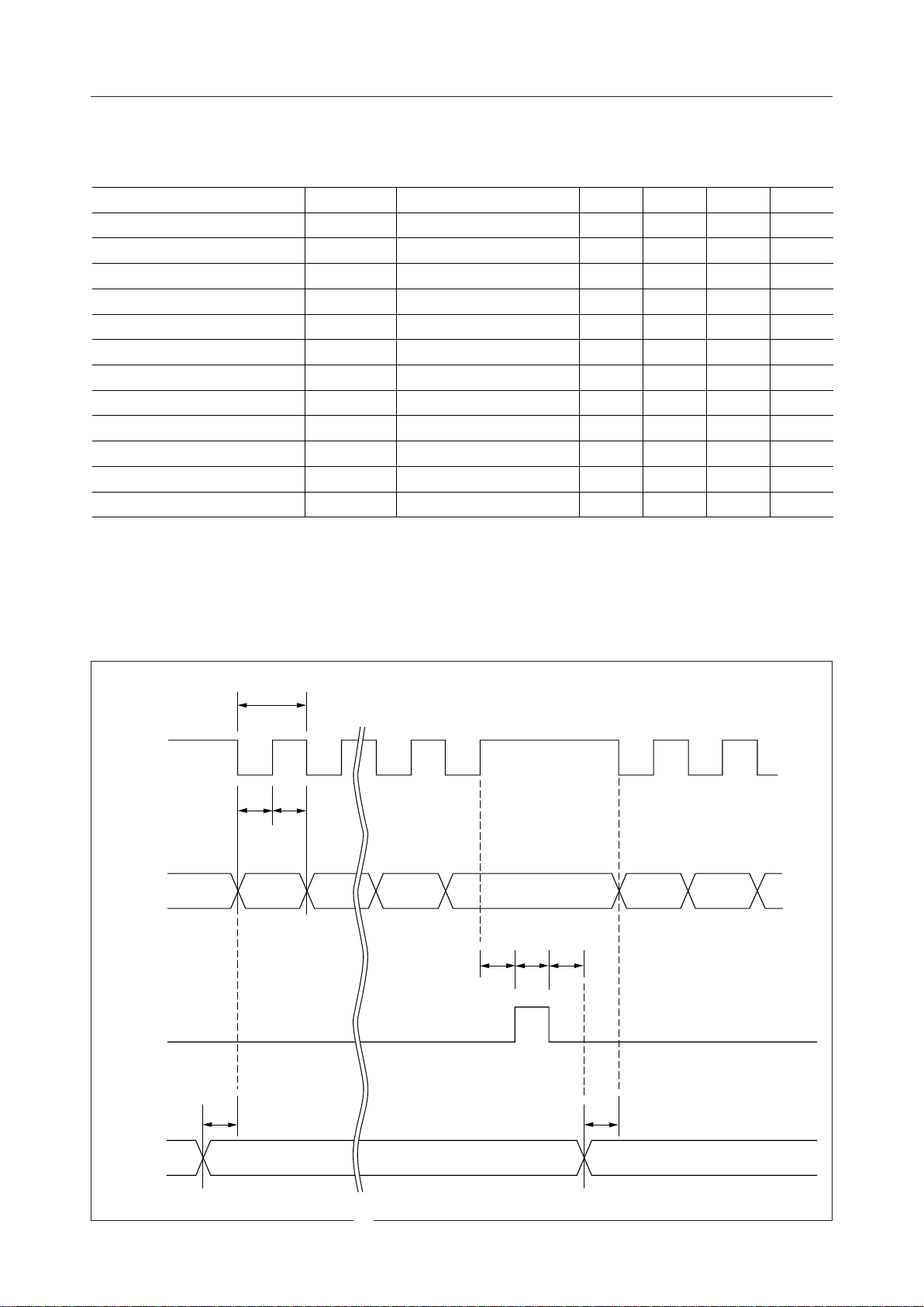
AC Characteristics
Parameter Condition
SCK Clock Period
SI Data Setup Time t
SI Data Hold Time t
SCK-LATCH Time t
LATCH Pulse Width t
A/D Setup Time t
A/D Hold Time t
A/D-SCK Time t
POR, BLK Fall Time t
f, FRAM Rise Time t
f, FRAM Fall Time t
Frame Frequency f
Symbol Min.
FR
10
11
MSC5301B-02¡ Semiconductor
(VCC = 5V, Ta = –40 to +85°C)
Typ.—Max.—Unit
1
2
3
4
5
6
7
8
9
—t
—1——ms
—1——ms
—1——ms
— 15——ms
—1——ms
—1——ms
—1——ms
— ——20ms
CL = 50 pF — — 0.3 ms
CL = 50 pF — — 0.3 ms
*1 85 100 115 Hz
2
ms
*1 The dispersion for external resistors and capacitors is not included.
RS = 1kW, RT = 15kW, CT = 0.01mF, VCC = 4.5V to 5.5V
t
1
SCK
t
t
2
3
SI
t
t5t
4
7
LATCH
A/D
t
6
t
8
6/15
Page 7
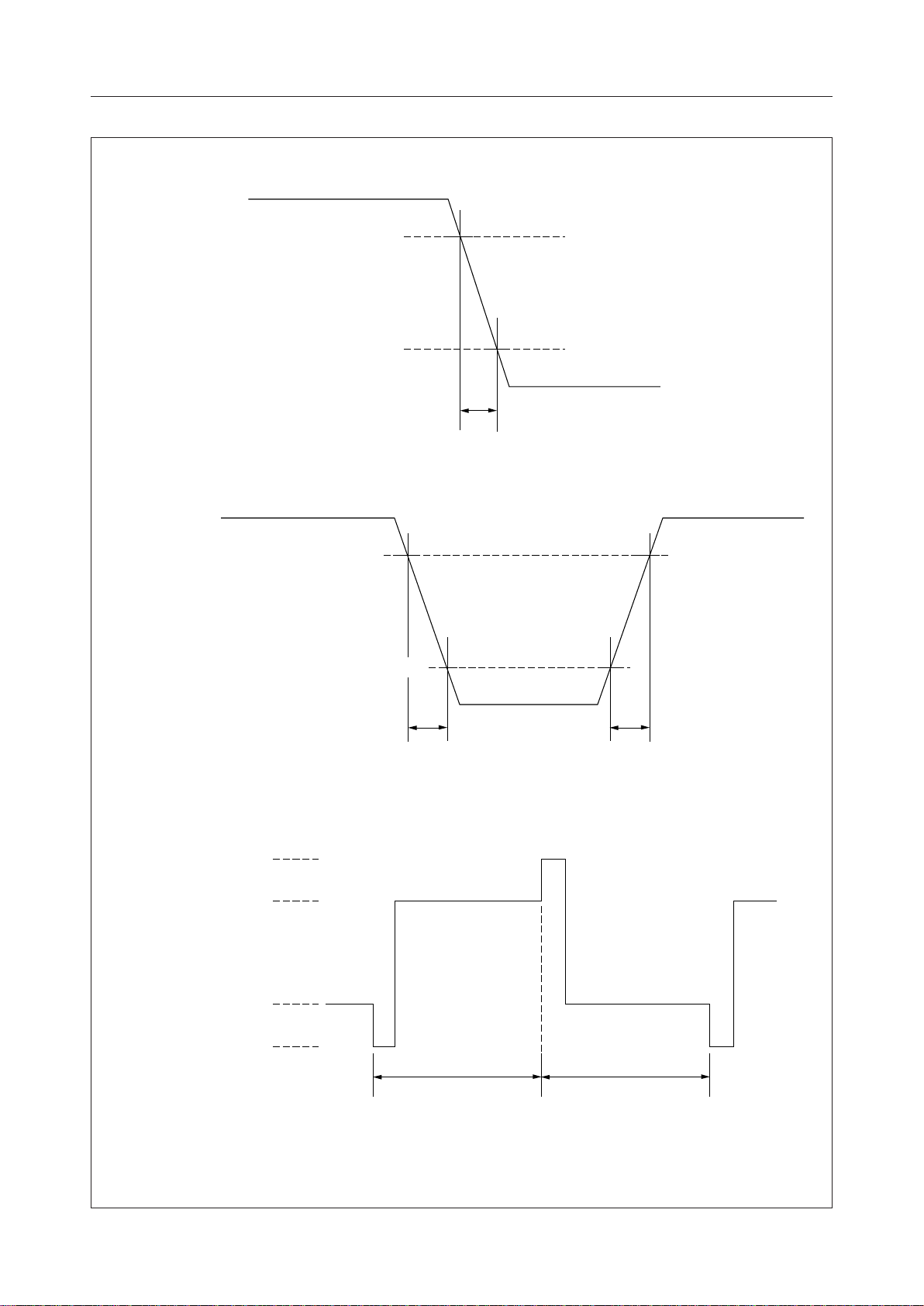
POR, BLK
MSC5301B-02¡ Semiconductor
V
CC
90%
10%
GND
t
9
V
CC
f, FRAM
C0
90%
10%
GND
t
11
V
DSP
V
1
t
10
V
GND
4
1/f
FR
1/f
FR
Frame A Frame B
7/15
Page 8
MSC5301B-02¡ Semiconductor
FUNCTIONAL DESCRIPTION
Pin Functional Description
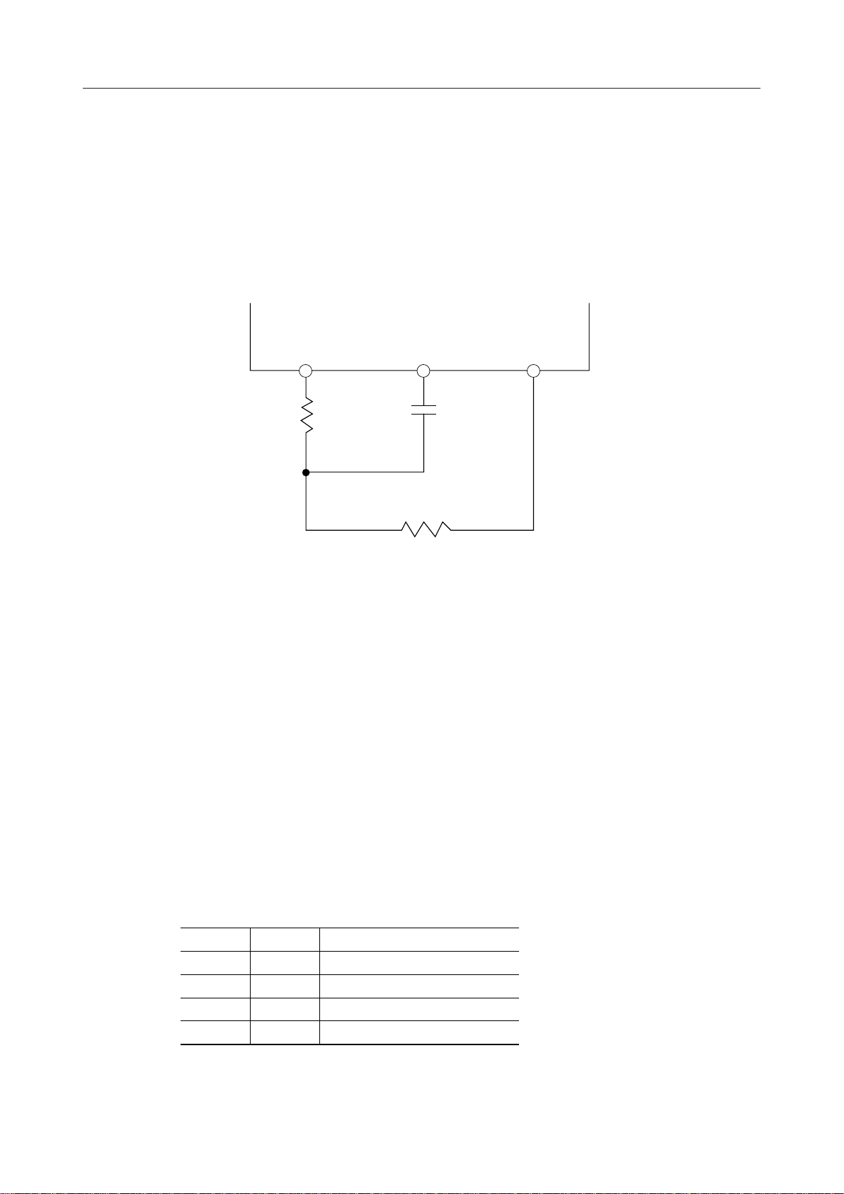
• OS1 (Pin 39), OS2 (Pin 40), f (Pin 41)
These are pins for the RC oscillation circuit. Connect external resistors and a capacitor as shown
below. When inputting the external clock pulse, input it to OS1 pin. OS2 and f pins should be
left open.
OS
1
R
S
OS
R
2
C
T
T
f
The relation of frame frequency fFR and internal clock frequency ff is shown by the following
equation.
(RC oscillation frequency = internal clock frequency)
ff = 4 x 8 x f
FR
In addition, the relation of frame frequency fFR and frame synchronizing signal frequency
f
is shown by the following equation.
FRAM
f
FRAM
= fFR/2
• CS0 (Pin 30), CS1 (Pin 31)
Chip select input pins. Master and slave modes are determined by CS0 and CS1 as shown in
the table below. A maximum of 4 devices can be connected in this manner. Use the master mode
when using a single chip.
CS0
L
H
L
H
CS1
L
L
H
H
Operation mode
Master mode
Slave mode
Slave mode
Slave mode
H : VCC level
L : GND level
8/15
Page 9

MSC5301B-02¡ Semiconductor
• FRAM (Pin 38)
This is an input and output pin for the frame synchronizing signal to be used for master/slave
configuration. It becomes an output pin in master mode and an input pin in slave mode.
• SI (Pin 34)
This is a serial data input pin of address data (8 bits) and segment data (64 bits). A pull-up
resistor (10 kW - 60 kW) and the Schmitt circuit are contained. The serial data is shifted at the
rising edge of SCK.
• SCK (Pin 35)
This is a shift clock input pin of address data (8 bits) and segment data (64 bits). The serial data
is shifted at the rising edge of SCK pulse. A pull-up resistor (10 kW - 60 kW) and the Schmitt
circuit are contained.
• LATCH (Pin 32)
This is a latch pulse input pin of address data (8 bits) and segment data (64 bits). The latch data
comes through at "H" level of LATCH and the data just before "H" level is latched at "L" level.
A pull-up resistor (10 kW - 60 kW) and the Schmitt circuit are contained.
•A/D (Pin 33)
This is a data select signal input pin of address data (8 bits) and segment data (64 bits). "H" level
is set in the case of address 8-bit input and "L" level is set in the case of segment data 64-bit input.
A pull-up resistor (10 kW - 60 kW) and the Schmitt circuit are contained.
•V
(Pin 44), V1 (Pin 29), V2 (Pin 45), V3 (Pin 46), V4 (Pin 28), VCC (Pin 42), GND (Pin 43)
DSP
These are power supply pins for this LSI and bias power supply pins for LCD driving.
VCC, which is a power supply pin, is from 4.5V to 5.5V; GND, which is a ground pin, is 0V; V
which is an LCD driving power supply pin, is usually used in the range between 6V and 16V.
V1, V2, V3 and V4 are bias power supply pins for LCD driving and are usually used by
supplying bias voltage from an external source.
DSP
,
9/15
Page 10

MSC5301B-02¡ Semiconductor
• BLK (Pin 37)
This is an input pin to control the LCD panel display.
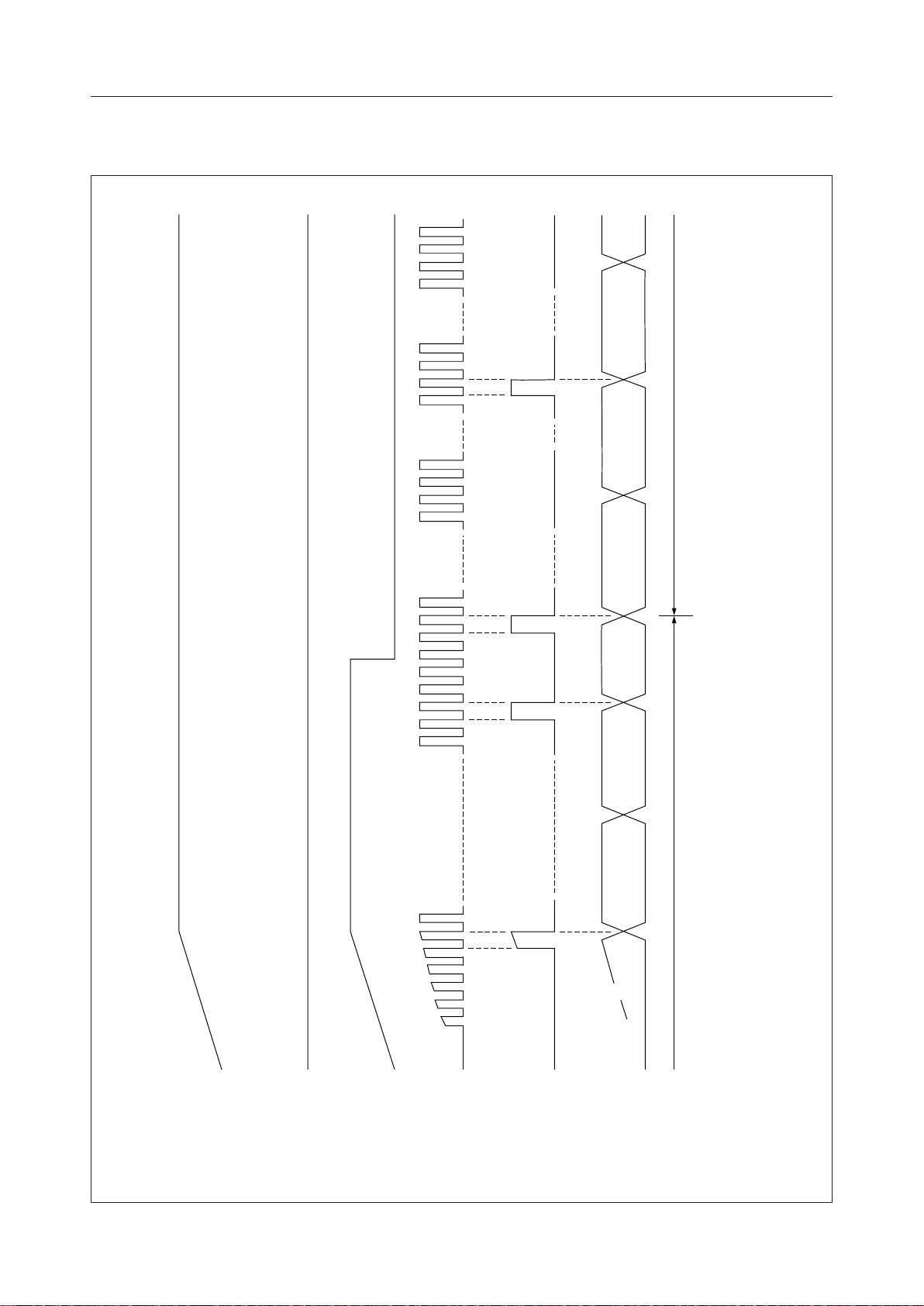
When a "H" level is input (or when this pin is open), the segment output pins S0 - S63 come to
the levels V2 - V3 and the LCD panel is turned off. In addition, during this period, the data read
from a display RAM is stopped but writing into the display RAM of address and segment data
inputted from the SI pin is available.
When this pin is changed from "H" level to "L", the frame synchronizing signal FRAM is output
within the 2 cycles of an internal clock ff, and it is synchronized at multi-chip. Then, the display
RAM address is set to "000". After 1/8 frame cycle from FRAM signal generation, the output
is applied from the "001" data of the display RAM address to the segment driver. Because the
display RAM contents are undefined at the time the power is turned on, keep this pin to "H"
level (or leave open) until writing data to the RAM is completed. A pull-up resistor (10kW 60kW) and the Schmitt circuit are contained.
• POR (Pin 36)
This is a power-on-reset input pin. When a "H" level is input (or when this pin is open), the
common and segment outputs come to the static light-out state in no relation to the BLK pin
and the segment output pins S0 - S63 become V3 level and the common output pins C0 - C8
become V4 level.
When this pin is changed from "H" level to "L", the frame synchronizing signal FRAM is output
within the 2 cycles of an interval clock ff, and it is synchronized when multiple devices are
connected and is moreover dynamic-operated from the frame B . Then, the display RAM
address is set to "000". After 1/8 frame cycle from FRAM signal generation, the "001" data of
the display RAM address is output to the segment driver. However, because the BLK pin is
usually at "H" level when the power-on-reset is released, reading data from the display RAM
is stopped and light-out segment data is forcibly transferred to the segment output. A pull-up
resistor (10kW - 60kW) and the Schmitt circuit are contained.
• C0 (Pin 13) - C7 (Pin 27)
These are 8-output pins of the common driver which are used for LCD panel driving. The
outputs of 4 levels are obtained (V
and GND are select levels, and V1 and V4 are nonselect
DSP
levels).
• S0 (Pin 47) - S63 (Pin 11)
These are 64-output pins of segment driver which are used for LCD panel driving. The outputs
of 4 levels are obtained (V
and GND are select levels, which correspond to "1" of the display
DSP
RAM data, and V2 and V3 are nonselect levels, which correspond to "0" of the display RAM
data).
NOTES ON USE
Note the following when turning power on and off:
The LCD drivers of this IC require a high voltage. For this reason, if a high voltage is applied to
the LCD drivers with the logic power supply floating, excess current flows. This may damage
the IC. Be sure to carry out the following power-on and power-off sequences:
When turning power on:
First VCC ON, next V
When turning power off:
First V
, V4, V3, V2, V1 OFF, next VCC OFF. Or both OFF at the same time.
DSP
, V4, V3, V2, V1 ON. Or both ON at the same time.
DSP
10/15
Page 11
MSC5301B-02¡ Semiconductor
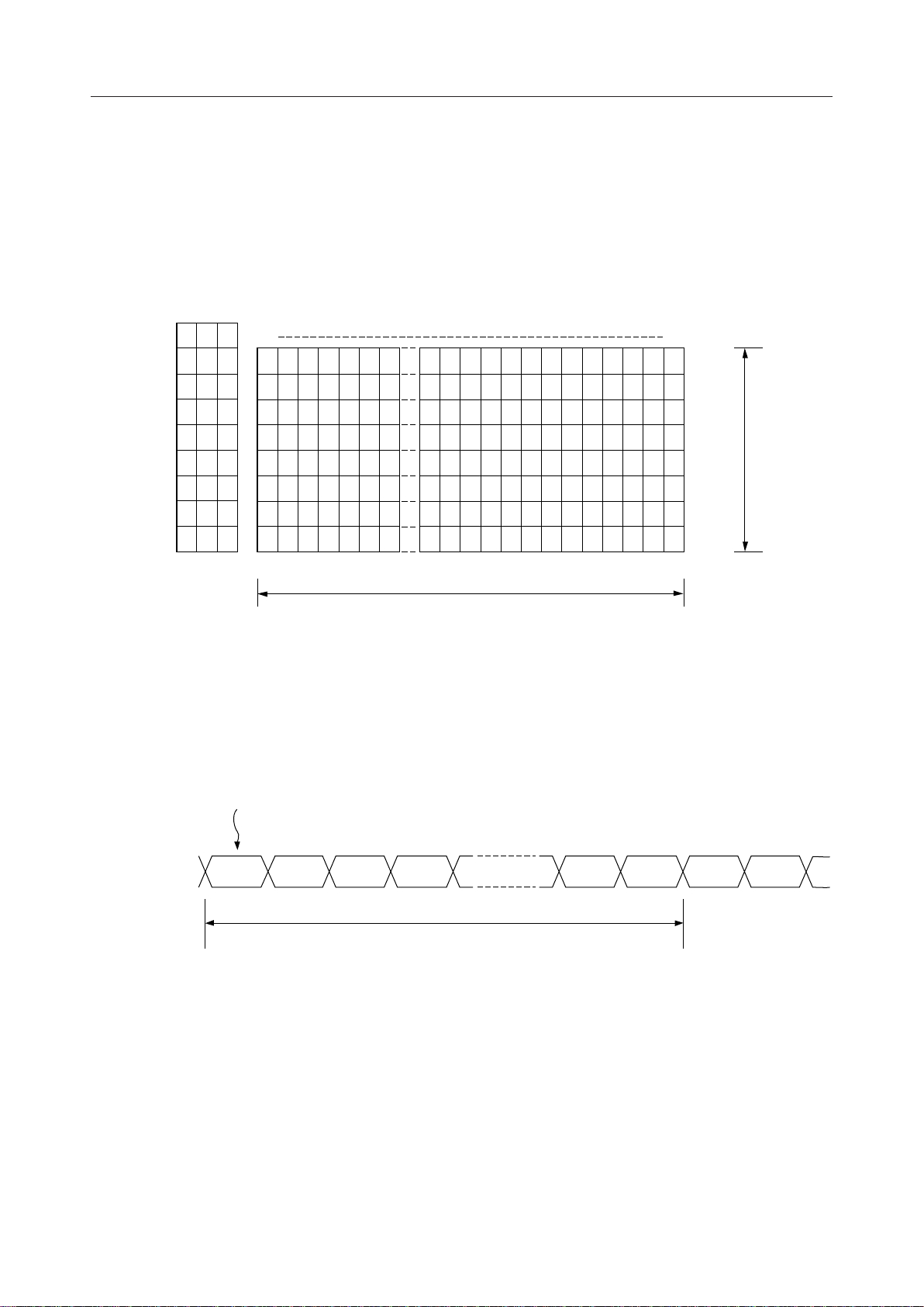
Relation Between LCD Screen Size and Display RAM
This LCD driver has a built-in RAM for the display of 8 ¥ 64 = 512 bits and the address
corresponds to the duty of the LCD.
The data corresponds to the number of dots in the X direction. The relation between the LCD
screen size and the display RAM is shown below.
Address Data
A2
A1
A0
S63 S0
0
0
0
0
0
1
0
1
0
0
1
1
1
0
0
1
0
1
1
1
0
1
1
1
C0
C1
C2
C3
C4
C5
C6
C7
1/8 duty
Number of dots in X direction (64)
Relation Between Frame Cycle and Display RAM Data
The output of the display RAM data corresponds to the segment output. The relation between
the frame cycle and the display RAM data is as follows:
First line address
Segment output
(Contents of RAM)
000 001 010 011 110 111 000 001
1 frame cycle
11/15
Page 12
MSC5301B-02¡ Semiconductor
Multiple Configuration
This LCD driver can form multiple configuration.
It is possible to form a maximum of 4 devices (a panel of up to 256 ¥ 8 dots in size can be formed)
by using chip select signals CS0 and CS1. The devices in multiple configuration must be
synchronized with one another. In this configuration, one device in the master mode, where the
original oscillation signal f and the synchronous signal FRAM are output, and the other devices
in the slave mode, where the original oscillation signal f and the synchronous signal FRAM are
input, are used in combination.
Refer to items CS0 and CS1 of the pin description on the mode setting method.
The original oscillation signal output pin f of the master mode devices is connected to the OS1
pin of the slave mode device and the synchronizing signal pin FRAM is also connected to the
FRAM pin of the slave mode device.
Connect SI, SCK, LATCH, A/D, POR and BLK of the master mode devices to SI, SCK, LATCH,
A/D, POR and BLK of each of the slave mode devices and connect them to CPU for control.
In addition, connect the devices so that V
, V1, V2, V3, V4 and GND are shared between the
DSP
devices, and connect them to each voltage level divided by resistors.
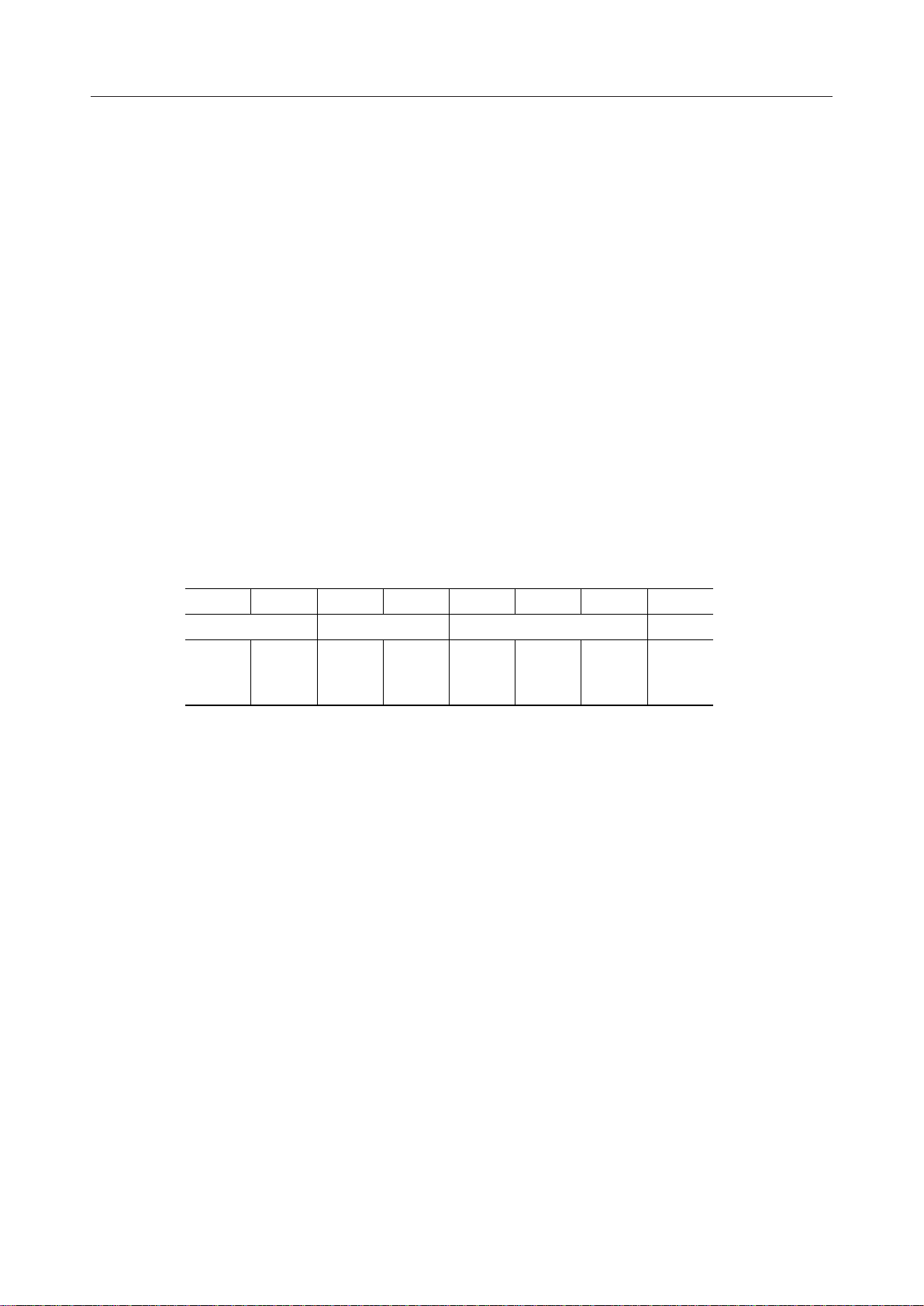
Address Data Configuration
(MSB) (LSB)
7654 3210
Dummy data 2 Upper address Lower address
DM2 DM1 CS1 CS0 A2 A1 A0 DM0
2 bits 2 bits
3 bits 1 bit
Dummy data 1
The lower address, which is the address of the display RAM, corresponds to the common sides
C0 - C7 of LCD panel. Dummy data 1 must be always set to "H".
The upper address corresponds to the logical state of chip select pins CS0 and CS1 and lower
address is set to the chip only with which corresponded.
For the chip to output the common signal (f, FRAM), set both of the upper address 2 bits to "L".
The 2 bits of dummy data can be set to either "L" or "H".
12/15
Page 13
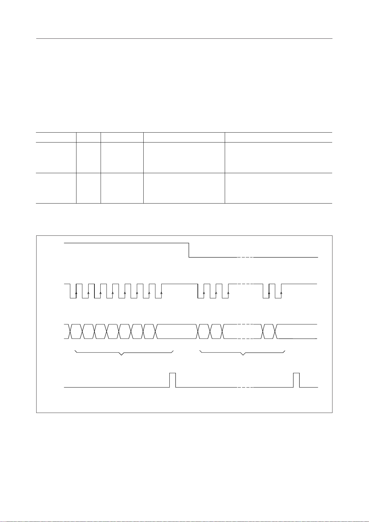
Serial Signal to be Input From CPU
g
The following signals are input from an external CPU to this LCD driver:
- Serial transfer clock Æ SCK
- Serial transfer data Æ SI
- Serial transfer latch Æ LATCH
- Serial data select Æ A/D
The operations are shown in the following table.
MSC5301B-02¡ Semiconductor
Mode LATCH SI
Address data
input mode
Segment data
input mode
H
L
SCKA/D
Shifts at the
rising edge
Shifts at the
rising edge
8-bit address data is latched
at falling edge (level type)
64-bit segment data is latched
at falling edge (level type)
8-bit address data
Serial input from LSB side
64-bit segment data
The first segment data shifted into the shift
register corresponds to S63.
"1" : Light-on data, "0" : Light-out data
Timing for Serial Signal Transferred From CPU
A/D
SCK
"H" at address data setting "L" at segment data setting
12345678 12 3 6364
SI
LATCH
Dummy
(Always "H")
A0 A1 A2 CS0 CS1 Dummy Dummy S63S62S
LSB
61
MSB
Address data (8 bits) Segment data (64 bits)
Address latch
si
nal
S1S
0
RAM write
signal
Notes:
1. Be sure to set the address before writing the segment data to RAM. Then, write the segment
data to RAM.
2. While the POR pin is "H" (upon power-on reset), neither address data nor segment data can
be entered.
13/15
Page 14
Operation upon Power ON (When Single Device Used)
MSC5301B-02¡ Semiconductor
Dynamic operation (normal operation)Dynamic light-out state
0 - 7 0 - 0 1 - 7 0 - 7 0 - 7 0 - 7
Frame B Frame B Frame A Frame AFrame BFrame BFrame A
Frame A
CC
V
POR
BLK
f
(External R
and C)
FRAM
Segment signal
output
Common signal output
RAM address 0 - 7
14/15
Page 15
PACKAGE DIMENSIONS
QFP100-P-1420-0.65-BK
Mirror finish
MSC5301B-02¡ Semiconductor
(Unit : mm)
Package material
Lead frame material
Pin treatment
Solder plate thickness
Package weight (g)
Epoxy resin
42 alloy
Solder plating
5 mm or more
1.29 TYP.
Notes for Mounting the Surface Mount Type Package
The SOP, QFP, TSOP, SOJ, QFJ (PLCC), SHP and BGA are surface mount type packages, which
are very susceptible to heat in reflow mounting and humidity absorbed in storage.
Therefore, before you perform reflow mounting, contact Oki’s responsible sales person for the
product name, package name, pin number, package code and desired mounting conditions
(reflow method, temperature and times).
15/15
 Loading...