

Page 1
S
SEMICONDUCTOR TECHNICAL DATA
The RF Line
Order this document
by MRFA2600/D
The MRFA2600 is a solid state class A amplifier and is specifically designed
for TV transposers and transmitters. This amplifier incorporates microstrip
technology and reliable Motorola push–pull transistors.
• Specified 26.5 Volts: 470–860 MHz Characteristics
Output Power: 25 Watts Min @ 1 dB Comp. (CW)
Gain: 10.5 dB Min (Small Signal)
• Suitable for 28 Volts Application
• 50 Ω Input and Output Impedance
MAXIMUM RATINGS
Rating Symbol Value Unit
Supply Voltage V
Current I
Storage Temperature Range T
Operating Temperature (1) T
NOMINAL OPERATION CONDITION
upply
Transposer Application VCC = 26.5 V I
Transmitter Application VCC = 28 V I
CC
max
stg
op
25 W, 470–860 MHz
CLASS A
RF POWER AMPLIFIER
CASE 429A–02
STYLE 1
29 Vdc
4 Adc
–40 to +100 °C
–20 to +70 °C
= 3.8 A
sup
= 3.6 A
sup
ELECTRICAL CHARACTERISTICS (T
Characteristic
Instantaneous Bandwidth BW 470 860 MHz
Power Gain (small signal) G
Gain Ripple (small signal) G
Output Power @ 1 dB Compression P
Mismatch Tolerance (P
Intermodulation (–8 dB/–16 dB/–10 dB, P
Intermodulation (–8 dB/–16 dB/–7 dB, P
Input Return Loss IRL 15 — dB
(1) Temperature is measured at temperature test point (on the flange of the transistor).
REV 3
= 25 W) VSWR
out
Motorola, Inc. 1997
= 25°C, VCC = 26.5 V, I
C
= 20 W) IMD — –52.5 dB
ref
= 20 W) IMD — –50 dB
ref
= 3.8 A, unless otherwise noted)
sup
Symbol Min Max Unit
p
rple
out
10.5 — dB
— ±1 dB
25 — W
1
:1
— —
ref
ref
MRFA2600MOTOROLA RF DEVICE DATA
1
Page 2
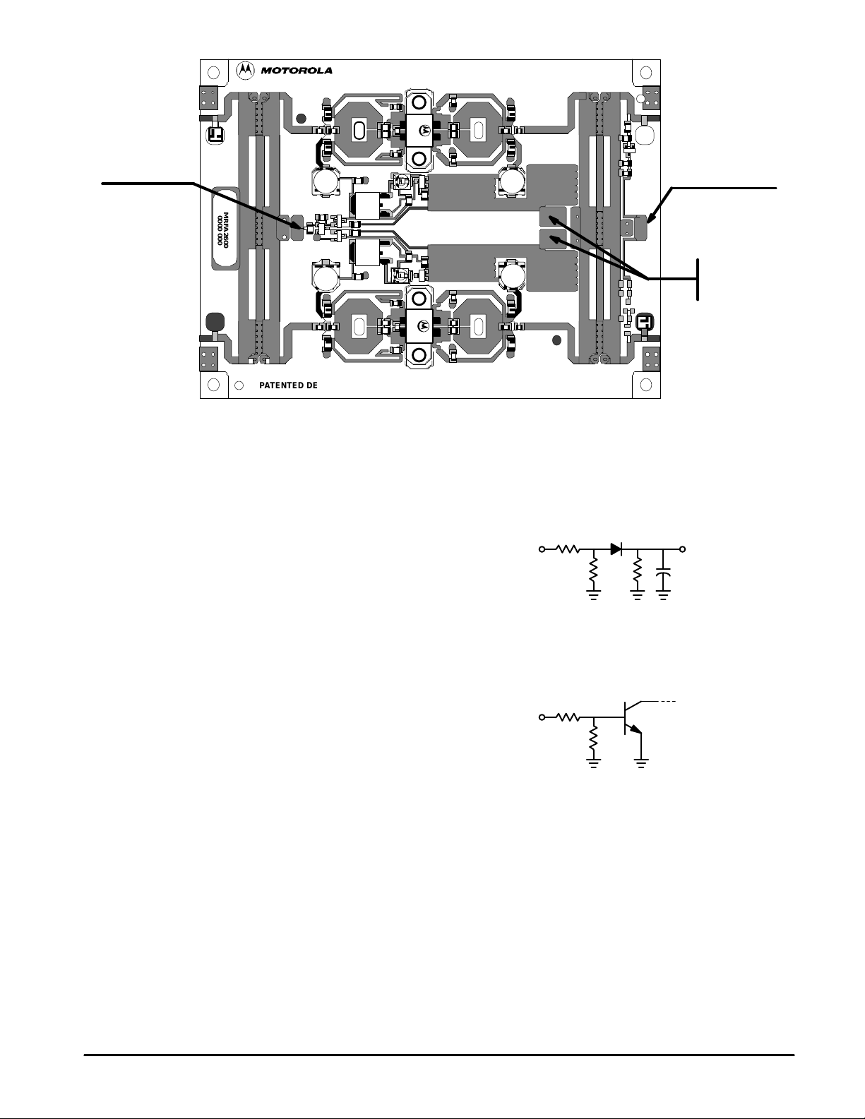
OUTPUT
ÀÀ
ÀÀ
BIAS REMOTE
INPUT
RF DETECTION
VD = 1 V @ 25 W
on infinite load
DATE/SERIAL
MRFA2600
0000 000
PATENTED DESIGN
Figure 1. MRFA2600 Connections
C1 22 pF
D1 MMBD701
R1 22 kΩ
R2 680 Ω
R3 2.2 kΩ
RF VIDEO
84ASTBB514C
ISSUE E
R1
D1
R2 R3 C1
RF DETECTION
V
CC1
V
CC2
BIAS REMOTE
MRFA2600
2
If B.R. = “1” (TTL signal)
bias circuit is off
R1 4.7 kΩ
R2 4.7 kΩ
T1 BCX20.
B.R.
R1
T1
R2
MOTOROLA RF DEVICE DATA
Page 3

MOUNTING RECOMMENDA TIONS
0.03
8 Fixing holes M3
Minimum useful depth: — Copper/Aluminum: 6 mm
HEATSINK TOOLING
Ra 0.8
• Flatness better than 0.03 mm.
• Roughness: Typical value 0.8.
THERMAL COMPOUND
• Paste with silicones: SICERONT KF Ref. 1201 Recommended.
• Thickness: Optimum between 0.06 mm and 0.15 mm, on the whole
back surface of the amplifier.
(Typical volume: 700 mm 3 for 0.1 mm thickness)
(Equivalent weight: 1.5g for 2.2 density paste).
SCREWS
• Socket head cap screws: — CHC M3 x 10 for Copper/Aluminum Heatsink.
• Material: Nickel plated steel.
WASHERS
• Split lock washers WZ ∅3 + Flat washers ZU ∅3.
CLEANING
• Some components of this amplifier are not qualified for every kind of cleaning solvent.
• Do not clean the amplifier in a solvent bath.
• Local cleaning is recommended.
MRFA2600MOTOROLA RF DEVICE DATA
3
Page 4

P ACKAGE DIMENSIONS
COMPONENT
AREA
NOTES:
1. DIMENSIONING AND TOLERANCING PER ANSI
F
W
M
A
E
D
L
G
2
P
K
B
C
5
6
1
Q
S 4 PL
3
8
4
H
I
T
N
U
7
X
J
R 4 PL
STYLE 1:
PIN 1. RF INPUT
2. RF OUTPUT
3. +VCC1 – (GROUND TO CASE)
4. +VCC2 – (GROUND TO CASE)
5. BIAS REMOTE
6. GROUND (BIAS REMOTE ONLY)
7. RF DETECTION
8. GROUND (RF DETECTION ONLY)
V
GROUND TO CASE
Y14.5M, 1982.
2. CONTROLLING DIMENSION: MILLIMETER.
MILLIMETERS
DIMAMIN MAX MIN MAX
B 3.342 3.35184.88 85.12
C 0.1423.60
D 2.154 2.16154.70 54.90
E 4.386 4.394111.40 111.60
F 0.134 0.1423.40 3.60
G 0.575 0.60614.60 15.40
H 3.492 3.52488.70 89.50
I 4.311 4.343109.50 110.30
J 2.913 2.92174.00 74.20
K 3.205 3.21381.40 81.60
L ––– 0.472––– 12.00
M 0.984 0.99225.00 25.20
N 1.669 1.67742.40 42.60
P 2.740 2.77269.60 70.40
Q 0.906 0.93723.00 23.80
R 0.134 0.1463.40 3.70
S 0.125 0.1353.18 3.42
T 1.539 1.57139.10 39.90
U 1.776 1.80745.10 45.90
V 0.177 0.1934.50 4.90
W 0.425 0.43310.80 11.00
X 2.354 2.36259.80 60.00
INCHES
4.523 4.532114.88 115.12
0.1343.40
CASE 429A–02
ISSUE A
Motorola reserves the right to make changes without further notice to any products herein. Motorola makes no warranty, representation or guarantee regarding
the suitability of its products for any particular purpose, nor does Motorola assume any liability arising out of the application or use of any product or circuit,
and specifically disclaims any and all liability, including without limitation consequential or incidental damages. “T ypical” parameters can and do vary in different
applications. All operating parameters, including “T ypicals” must be validated for each customer application by customer’s technical experts. Motorola does
not convey any license under its patent rights nor the rights of others. Motorola products are not designed, intended, or authorized for use as components in
systems intended for surgical implant into the body, or other applications intended to support or sustain life, or for any other application in which the failure of
the Motorola product could create a situation where personal injury or death may occur. Should Buyer purchase or use Motorola products for any such
unintended or unauthorized application, Buyer shall indemnify and hold Motorola and its officers, employees, subsidiaries, affiliates, and distributors harmless
against all claims, costs, damages, and expenses, and reasonable attorney fees arising out of, directly or indirectly, any claim of personal injury or death
associated with such unintended or unauthorized use, even if such claim alleges that Motorola was negligent regarding the design or manufacture of the part.
Motorola and are registered trademarks of Motorola, Inc. Motorola, Inc. is an Equal Opportunity/Affirmative Action Employer.
Literature Distribution Centers:
USA: Motorola Literature Distribution; P.O. Box 20912; Phoenix, Arizona 85036.
EUROPE: Motorola Ltd.; European Literature Centre; 88 T anners Drive, Blakelands, Milton Keynes, MK14 5BP, England.
JAPAN: Nippon Motorola Ltd.; 4-32-1, Nishi-Gotanda, Shinagawa-ku, Tokyo 141, Japan.
ASIA PACIFIC: Motorola Semiconductors H.K. Ltd.; Silicon Harbour Center , No. 2 Dai King Street, T ai Po Industrial Estate, Tai Po, N.T., Hong Kong.
MRFA2600
4
◊
MOTOROLA RF DEVICE DATA
*MRFA2600/D*
MRFA2600/D
 Loading...