

Page 1
UTC MPSA92 / 93 PNP EPITAXIAL SILICON TRANSISTOR
HIGH VOLTAGE PNP
TRANSISTOR
DESCRIPTION
The UTC MPSA92/93 are high voltage PNP
transistors, designed for telephone signal switching
and for high voltage amplifier.
FEATURES
* High Collector-Emitter voltage:
VCEO=-300V(UTC MPSA92)
VCEO=-200V(UTC MPSA93)
*Collector Dissipation:
Pc(max)=625mW
1
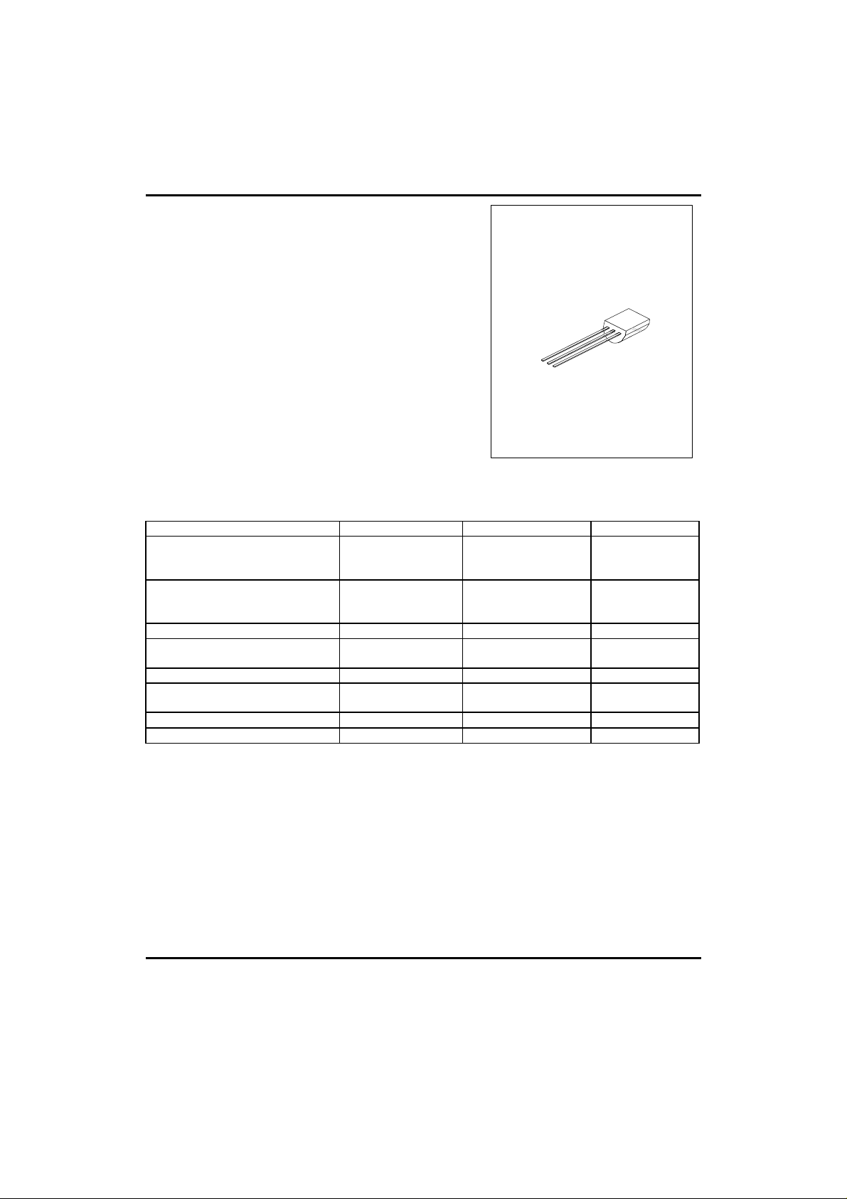
TO-92
1:EMITTER 2:BASE 3:COLLECTOR
ABSOLUTE MAXIMUM RATINGS ( Operating temperature range applies unless otherwise specified )
PARAMETER SYMBOL VALUE UNIT
Collector-Base Voltage
UTC MPSA92
UTC MPSA93
Collector-Emitter Voltage
UTC MPSA92
UTC MPSA93
Emitter-Base Voltage VEBO -5 V
Collector Dissipation(Ta=25°C)
Derate Above 25°C
Collector Current Ic -500 mA
Collector Dissipation(Tc=25°C)
Derate Above 25°C
Junction Temperature Tj 150 °C
Storage Temperature TSTG -55 ~ +150 °C
VCBO -300
-200
VCEO -300
-200
Pc 625
5
Pc 1.5
12
V
V
mW
mW/°C
W
mW/°C
UTC UNISONIC TECHNOLOGIES CO. LTD
1
Page 2
UTC MPSA92 / 93 PNP EPITAXIAL SILICON TRANSISTOR
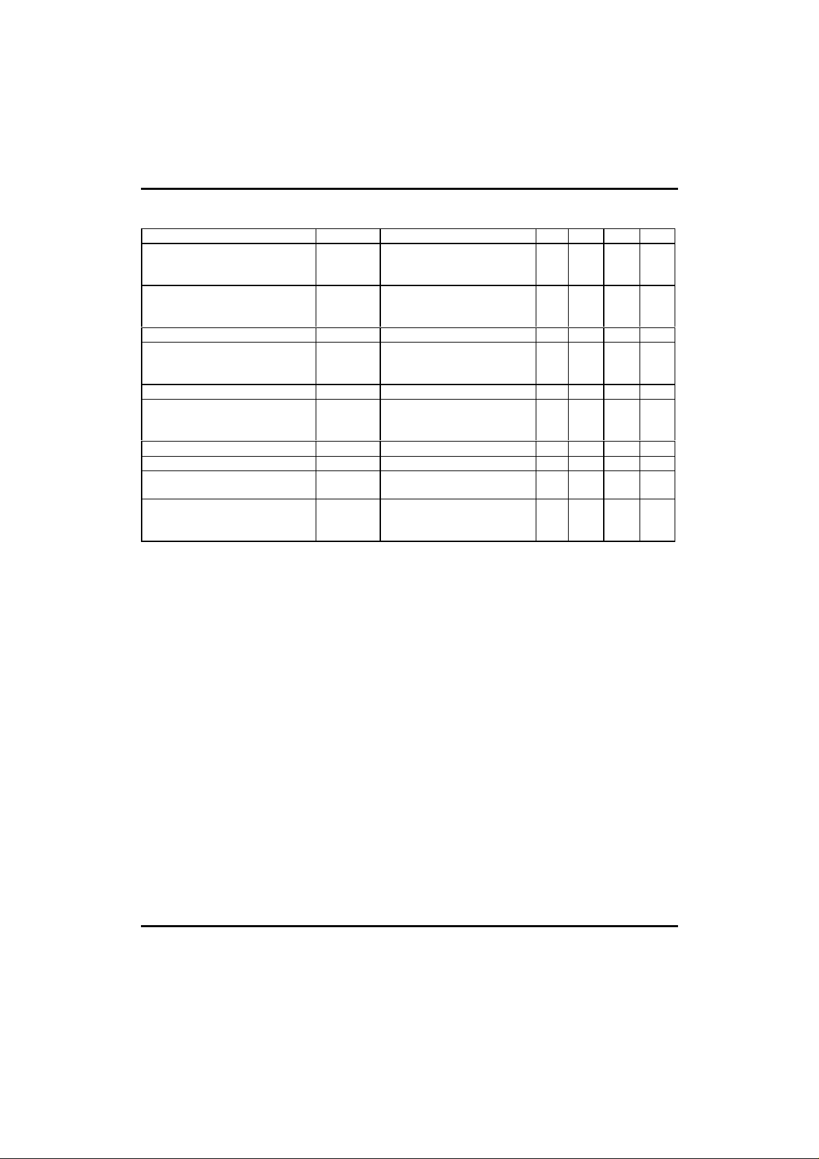
ELECTRICAL CHARACTERISTICS(Tj=25°C,unless otherwise specified)
PARAMETER SYMBOL TEST CONDITIONS MIN TYP MAX UNIT
Collector-Base Breakdown Voltage
UTC MPSA92
UTC MPSA93
Collector-Emitter Breakdown Voltage
UTC MPSA92
UTC MPSA93
Emitter-Base Breakdown Voltage BVEBO IE=-100µA,Ic=0 -5 V
Collector Cut-Off Current
UTC MPSA92
UTC MPSA93
Emitter Cut-Off Current IEBO VEB=-3V,Ic=0 -0.10 µA
DC Current Gain(note) hFE VCE=-10V,Ic=-1mA
Collector-Emitter Saturation Voltage VCE(sat)1 Ic=-20mA,IB=-2mA -0.5 V
Base-Emitter Saturation Voltage VBE(sat)1 Ic=-20mA,IB=-2mA -0.90 V
Current Gain Bandwidth Product fT VCE=-20V,Ic=-10mA,
Collector Base Capacitance
UTC MPSA92
UTC MPSA93
Note:Pulse test:PW<300µs,Duty Cycle<2%, VCE(SAT)1<200mV(Class SIN)
BVCBO Ic=-100µA,IE=0
BVCEO Ic=-1mA,IB=0
ICBO
VCB=-200V,IE=0
VCB=-160V,IE=0
VCE=-10V,Ic=-10mA
VCE=-10V,Ic=-30mA
f=100MHz
Ccb VCB=-20V,IE=0
f=1MHz 68pF
-300
-200
-300
-200
-0.25
-0.25
60
80
80
50 MHz
V
V
µA
UTC UNISONIC TECHNOLOGIES CO. LTD
2
Page 3
UTC MPSA92 / 93 PNP EPITAXIAL SILICON TRANSISTOR
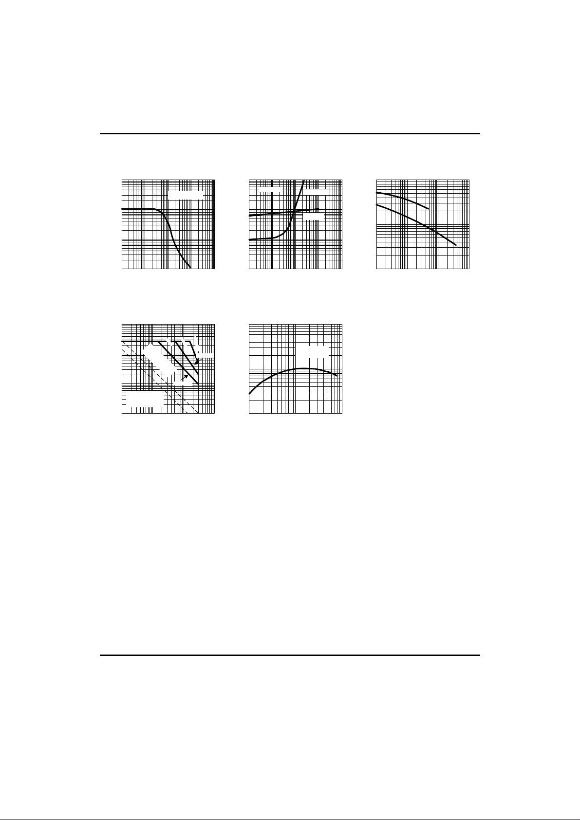
TYPICAL PERFORMANCE CHARACTERISTICS
Fig.1 DC Current Gain
3
10
VCE=-10V
FE
2
10
1
10
DC current Gain,H
0
10
-100-101-102-103-10
Collector current, Ic(mA)
4
Fig.2 Saturation Voltage
4
-10
Ic=10*I
B
VCE(sat)
3
-10
2
-10
VBE(sat)
VCE(sat),VBE(sat) (mV)
1
-10
-100-101-102-103-10
Collector current, Ic(mA)
Fig.3 Capacitance
2
10
CIB
(pF)
1
CB
10
(pF),C
IB
C
4
-1
-10
0
-10
CCB
1
-10
2
-10
Collector-Base voltage(V)
Fig.4 Active-region safe
625mW Thermal
limitation Ta=25¢XC
bonding breakdown
limitation Tj=150¢XC
0
-10
operating area
1.5W Thermal
limitation Tc=25
1
-10
3
-10
2
-10
1
-10
Collector current, Ic(mA)
1
-10
Collector-Emitter voltage ( v)
Fig.5 Current Gain
Bandwidth product
3
10
0.1ms
1.0ms
DC
MPSA93
¢X
C
MPSA92
2
10
product(MHz)
VCE=-20V
f=100MHz
Current gain bandwidth
1
2
-10
-10
10
3
0
-10
1
-10
2
-10
Collector current, Ic(mA)
UTC UNISONIC TECHNOLOGIES CO. LTD
3
 Loading...