

Page 1
MPS MANUAL
MOTOR PROTECTION SYSTEM
Revision 6-F-022117
Copyright © 2017 by Littelfuse Startco
All rights reserved.
Document Number: PM-1130-EN
Page 2

Factory default password is 1111
New Password
See Section 4.3.6.
Motor Identification
Page 3

Page ii
MPS Motor Protection System Rev. 6-F-022117
. Table of Contents
TABLE OF CONTENTS
SECTION PAGE
List of Figures ....................................................................... iv
List of Tables ........................................................................ iv
Disclaimer .............................................................................. v
1 Introduction .......................................................... 1-1
1.1 General .................................................................... 1-1
1.2 MPS Features .......................................................... 1-1
1.2.1 Protection .................................................... 1-1
1.2.2 Control – Starting Methods ........................ 1-1
1.2.3 Metering ...................................................... 1-1
1.2.4 Data Logging .............................................. 1-1
1.2.5 Inputs and Outputs ...................................... 1-1
1.2.6 MPS-OPI Operator Interface ..................... 1-2
1.2.7 MPS-RTD Module ..................................... 1-2
1.2.8 MPS-DIF Differential Module ................... 1-2
1.2.9 Communications Interface ......................... 1-2
1.3 Ordering Information .............................................. 1-2
2 Installation ............................................................. 2-1
2.1 General .................................................................... 2-1
2.2 MPS-CTU Control Unit ......................................... 2-1
2.3 MPS-OPI Operator Interface .................................. 2-1
2.4 MPS-RTD Module ................................................. 2-1
2.5 MPS-DIF Differential Module ............................... 2-1
2.6 Earth-Fault CT’s ..................................................... 2-1
3 System Wiring ....................................................... 3-1
3.1 General .................................................................... 3-1
3.2 Wiring Connections ................................................ 3-1
3.2.1 MPS-CTU Connections ............................. 3-1
3.2.1.1 Supply Voltage .............................. 3-1
3.2.1.2 Current Inputs ................................ 3-1
3.2.1.3 Voltage Inputs ............................... 3-1
3.2.1.3.1 Direct Connection ........ 3-3
3.2.1.3.2 1-PT Connection .......... 3-3
3.2.1.3.3 2-PT Connection .......... 3-3
3.2.1.3.4 3-PT Connection .......... 3-3
3.2.1.4 Digital Inputs ................................. 3-3
3.2.1.4.1 DC Operation ............... 3-4
3.2.1.4.2 AC Operation ............... 3-4
3.2.1.4.3 Combined AC and
DC Operation ............................... 3-4
3.2.1.4.4 Tachometer
Input (HSI) ................................... 3-4
3.2.1.5 Analog Input (AN IN) ................... 3-4
3.2.1.6 Analog Output (AN OUT) ............ 3-4
3.2.1.7 PTC Input ...................................... 3-4
3.2.1.8 IRIG-B Input ................................. 3-4
3.2.1.9 I/O Module Communication ......... 3-4
3.2.1.10 RS-485 Network
Communications ......................................... 3-4
3.2.2 MPS-OPI Connections and
Address Selection ....................................... 3-4
3.2.3 MPS-RTD Connections and
Address Selection ....................................... 3-5
3.2.4 MPS-DIF Connections ............................... 3-5
3.2.4.1 Core Balance ................................. 3-5
TABLE OF CONTENTS
SECTION PAGE
3.2.4.2 MPS Summation ............................ 3-5
3.2.4.3 DIF Summation ............................. 3-5
3.2.5 Dielectric-Strength Testing ........................ 3-5
4 Operation and Setup ............................................ 4-1
4.1 General .................................................................... 4-1
4.2 MPS-CTU ............................................................... 4-1
4.2.1 LED Indication ........................................... 4-1
4.2.2 Reset Switch ................................................ 4-1
4.2.3 Phase-CT Inputs .......................................... 4-1
4.2.4 Earth-Fault-CT Input .................................. 4-2
4.2.5 Voltage Inputs ............................................. 4-2
4.2.6 Motor Data .................................................. 4-2
4.2.7 Output Relay Assignment .......................... 4-2
4.2.8 Digital Inputs 1 to 7 .................................... 4-3
4.2.9 Tachometer Input (HSI) ............................. 4-4
4.2.10 Analog Output ............................................. 4-4
4.2.11 Analog Input ............................................... 4-5
4.2.11.1 Metering only .............................. 4-5
4.2.11.2 Protection ..................................... 4-5
4.2.11.3 Synchronize to ASD .................... 4-5
4.2.11.4 Motor Speed ................................ 4-5
4.2.12 Starter .......................................................... 4-5
4.2.13 Protection .................................................... 4-5
4.2.14 Miscellaneous Configuration ..................... 4-5
4.2.15 Network Communications .......................... 4-5
4.3 MPS-OPI ................................................................. 4-5
4.3.1 General ........................................................ 4-5
4.3.2 Configuring the MPS-CTU for
OPI Operation ............................................. 4-5
4.3.3 Starter Control ............................................. 4-6
4.3.3.1 OPI Control .................................... 4-6
4.3.3.2 Local Control ................................. 4-6
4.3.3.3 Remote Control ............................. 4-6
4.3.4 Metering ...................................................... 4-7
4.3.5 Messages ..................................................... 4-7
4.3.5.1 Trip Reset ....................................... 4-7
4.3.5.2 Status .............................................. 4-7
4.3.5.3 Data Logging ................................. 4-9
4.3.5.4 Statistical Data ............................... 4-9
4.3.5.5 Emergency Thermal Reset ............ 4-9
4.3.6 Password Entry and Programming ............. 4-9
4.4 MPS-RTD ............................................................. 4-10
4.5 MPS-DIF ............................................................... 4-10
4.6 Waveform Capture ............................................... 4-10
5 Protective Functions ......................................... 5-1
5.1 General ............................................................... 5-1
5.2 Overload ............................................................. 5-1
5.2.1 Thermal Model ....................................... 5-1
5.2.2 Locked-Rotor Times ............................... 5-4
5.2.3 Emergency Thermal Reset ...................... 5-4
5.3 Overcurrent ........................................................ 5-4
5.4 Auxiliary Overcurrent ........................................ 5-5
5.5 Reduced Overcurrent ......................................... 5-5
5.6 Jam ..................................................................... 5-5
5.7 Earth Fault .......................................................... 5-5
Page 4

Page iii
MPS Motor Protection System Rev. 6-F-022117
. Table of Contents
SECTION PAGE
5.8 Current Unbalance .............................................. 5-5
5.9 Phase Loss—Current .......................................... 5-6
5.10 Phase Reverse—Current ..................................... 5-6
5.11 Undercurrent ....................................................... 5-6
5.12 Overvoltage ........................................................ 5-6
5.13 Voltage Unbalance ............................................. 5-6
5.14 Phase Loss—Voltage ......................................... 5-6
5.15 Phase Reverse—Voltage .................................... 5-6
5.16 Undervoltage ...................................................... 5-7
5.17 Underpower ........................................................ 5-7
5.18 Reversepower ..................................................... 5-7
5.19 Power Factor—Quadrant 4 ................................. 5-7
5.20 Power Factor—Quadrant 3 ................................. 5-7
5.21 Underfrequency .................................................. 5-7
5.22 Overfrequency .................................................... 5-8
5.23 Starts per Hour/Time Between Starts ................. 5-8
5.24 Failure to Accelerate and Underspeed ................ 5-8
5.25 Differential Current Protection ........................... 5-9
5.26 PTC Temperature ............................................... 5-9
5.27 RTD Temperature .............................................. 5-9
5.28 Hot-Motor Compensation ................................ 5-10
5.29 Analog Input ..................................................... 5-10
5.29.1 Protection .............................................. 5-10
5.29.2 Synchronize to ASD ............................. 5-10
5.29.3 Motor Speed .......................................... 5-10
5.29.4 Metering Only ....................................... 5-10
6 Starter Functions .............................................. 6-1
6.1 General ............................................................... 6-1
6.2 Starter Timing Sequences ................................... 6-4
6.3 Full-Voltage Non-Reversing Starter .................. 6-7
6.4 Adjustable-Speed Drive ..................................... 6-7
6.5 Soft-Start Starter ................................................. 6-7
6.6 Full-Voltage Reversing Starter ........................... 6-8
6.7 Two-Speed Starter .............................................. 6-8
6.8 Reactor or Resistor Closed-Transition
Starter ............................................................... 6-10
6.9 Slip-Ring Starter ............................................... 6-10
6.10 Part-Winding and Double-Delta Starters ......... 6-11
6.11 Soft-Start-With-Bypass Starter ........................ 6-12
6.12 Reactor or Resistor Open-Transition Starter .... 6-12
6.13 Two-Winding Starter ........................................ 6-12
6.14 Wye-Delta Open-Transition Starter ................. 6-12
6.15 Autotransformer Closed-Transition Starter ...... 6-13
6.16 Wye-Delta Closed-Transition Starter ............... 6-13
7 Theory of Operation ......................................... 7-1
7.1 Signal-Processing Algorithms ............................ 7-1
7.2 Power Algorithm ................................................ 7-1
7.3 Operator Interface (MPS-OPI) ........................... 7-1
7.4 RTD Module (MPS-RTD) ................................. 7-1
7.5 Differential Module (MPS-DIF) ........................ 7-1
7.6 Firmware Diagnostics ........................................ 7-1
8 Communications ............................................... 8-1
8.1 Personal-Computer Interface .............................. 8-1
8.1.1 Firmware Upgrade .................................. 8-1
8.1.2 SE-Comm-RIS ........................................ 8-1
SECTION PAGE
8.2 Network Interface ............................................... 8-1
8.2.1 RS-485 Communications ........................ 8-1
8.2.2 DeviceNet Communications ................... 8-1
8.2.3 Ethernet Communications ....................... 8-1
8.2.4 Profibus Communications ....................... 8-1
9 Technical Specifications ................................... 9-1
9.1 Control Unit (MPS-CTU) .................................. 9-1
9.2 Operator Interface (MPS-OPI) ........................... 9-3
9.3 RTD Module (MPS-RTD) ................................. 9-3
9.4 Differential Module (MPS-DIF) ........................ 9-4
10 Warranty ........................................................... 9-5
Appendix A MPS-OPI Menu Map ............................ A-1
Appendix B MPS Set-Up Record .............................. B-1
Appendix C MPS Modbus Protocol .......................... C-1
Appendix D MPS A-B DF1 Protocol ......................... D-1
Appendix E Communications Database Table ......... E-1
Appendix F Register Formats .................................... F-1
Appendix G MPS Revision History .......................... G-1
Page 5

Page iv
MPS Motor Protection System Rev. 6-F-022117
. Table of Contents
LIST OF FIGURES
FIGURE PAGE
1.1 Motor Protection System Block Diagram ............. 1-3
1.2 MPS Ordering Information .................................... 1-4
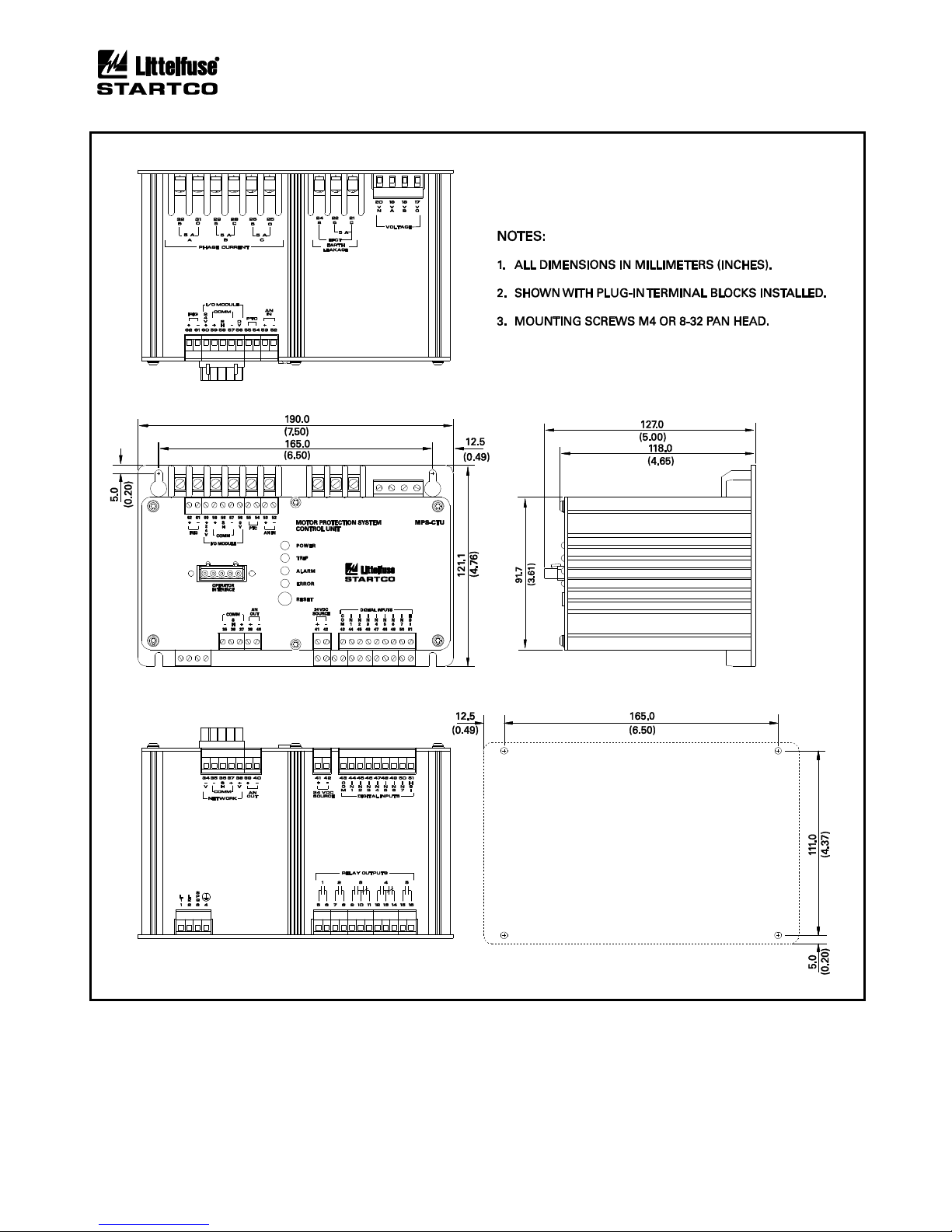
2.1 MPS-CTU Outline and Mounting Details ............. 2-2
2.1.1 MPS-CTU-XX-X1 Ring Terminal
Outline and Mounting Details ................................ 2-3
2.2 MPS-OPI Outline and Mounting Details ............... 2-4
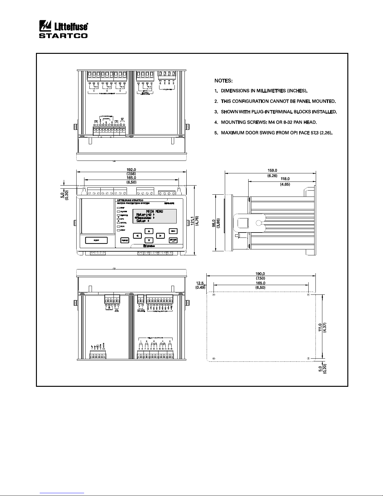
2.3 MPS-CTU with OPI Outline and
Mounting Details .................................................... 2-5
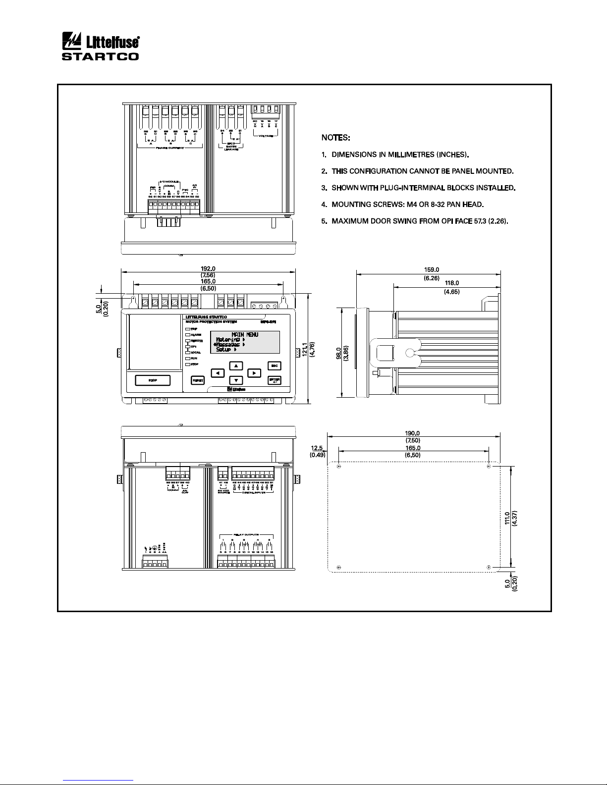
2.3.1 MPS-CTU Ring Terminal with OPI Outline and
Mounting Details .................................................... 2-6
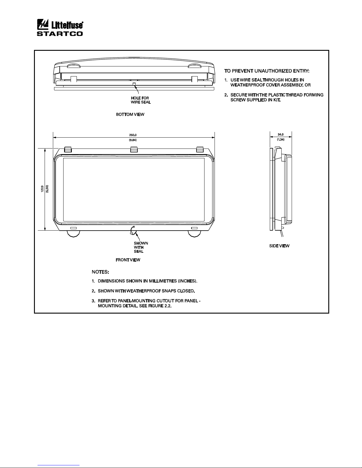
2.4 SE-IP65CVR-M Weatherproof Cover Outline .. 2-7
2.5 SE-IP65CVR-M Weatherproof Cover
Installation .......................................................... 2-8
2.6 MPS-RTD Outline and Mounting Details ............. 2-9
2.7 MPS-DIF Outline and Mounting Details ............. 2-10
2.8 EFCT-1 Outline and Mounting Details ............... 2-11
2.9 EFCT-2 Outline and Mounting Details ............... 2-12
2.10 EFCT-26 and SE-CS30-26 Outline and
Mounting Details .................................................. 2-13
2.11 SE-CS30-70 Outline and Mounting Details ........ 2-14
2.12 SE-CS30-4, -5, and -8 Outline and Mounting
Details ................................................................... 2-15
3.1 Residual Phase-CT Connection ............................. 3-1
3.2 Typical MPS Connection Diagram ........................ 3-2
3.3 Direct Connection ................................................... 3-3
3.4 1-PT Connection ..................................................... 3-3
3.5 2-PT Connection ..................................................... 3-3
3.6 3-PT Connection ..................................................... 3-3
3.7 Digital Tachometer Input (HSI) ............................. 3-4
3.8 Address Selection Switch Detail ............................ 3-5
3.9 Two Examples of I/O Module Connections .......... 3-6
3.10 MPS-RTD Connection Diagram ............................ 3-7
3.11 Core Balance Connection ....................................... 3-8
3.12 MPS Summation Connection ................................. 3-8
3.13 DIF Summation Connection .................................. 3-9
4.1 Menu Example ........................................................ 4-1
4.2 Menu Symbols ........................................................ 4-1
4.3 MPS-OPI Interface ................................................. 4-6
5.1 Class-20 Overload Curve ....................................... 5-3
5.2 Asymmetrical-Current Multipliers ......................... 5-5
5.3 Used I2t Bias Curve .............................................. 5-10
6.1 Typical 3-Wire Control .......................................... 6-3
6.2 Typical 2-Wire Control .......................................... 6-4
6.3 Starter Sequence 1 .................................................. 6-4
6.4 Starter Sequence 2 .................................................. 6-4
6.5 Starter Sequence 3 .................................................. 6-5
6.6 Starter Sequence 4 .................................................. 6-5
6.7 Starter Sequence 5 .................................................. 6-6
6.8 Starter Sequence 6 .................................................. 6-6
6.9 Full-Voltage Non-Reversing-Starter
Connection .............................................................. 6-7
6.10 Adjustable-Speed-Drive Connection ..................... 6-7
6.11 Soft-Start-Starter Connection ................................. 6-7
LIST OF FIGURES
FIGURE .............................................. PAGE
6.12 Full-Voltage-Reversing-Starter Connection .......... 6-8
6.13 Two-Speed Two-Winding-Starter Connection ...... 6-8
6.14 Two-Speed Constant- and Variable-Torque-
Starter Connections ................................................. 6-9
6.15 Two-Speed Constant-Horsepower-Starter
Connection ............................................................... 6-9
6.16 Reactor or Resistor-Starter Connection ................ 6-10
6.17 Slip-Ring-Starter Connection ................................ 6-10
6.18 Part-Winding and Double-Delta-Starter
Connections ........................................................... 6-11
6.19 Soft-Start-With-Bypass-Starter Connection ......... 6-12
6.20 Two-Winding-Starter Connection ........................ 6-13
6.21 Wye-Delta Open-Transition-Starter
Connection ............................................................. 6-14
6.22 Autotransformer Closed-Transition-Starter
Connection ............................................................. 6-14
6.23 Wye-Delta Closed-Transition-Starter
Connection ............................................................. 6-15
LIST OF TABLES
TABLE PAGE
3.1 MPS-OPI Address Selection ................................... 3-4
3.2 MPS-RTD Address Selection ................................. 3-5
4.1 Output-Relay Functions .......................................... 4-2
4.2 Digital-Input Functions ........................................... 4-3
4.3 Analog-Output Parameters ...................................... 4-4
4.4 Metering Display ..................................................... 4-8
4.5 Status Messages ....................................................... 4-8
5.1 Trip Time ................................................................. 5-4
5.2 Fault Duration Required for Trip ............................ 5-4
6.1 Start-Source Summary ............................................ 6-1
6.2 Starter Summary ...................................................... 6-3
Page 6

Page v
MPS Motor Protection System Rev. 6-F-022117
. Table of Contents
DISCLAIMER
Specifications are subject to change without notice.
Littelfuse Startco is not liable for contingent or
consequential damages, or for expenses sustained as a result
of incorrect application, incorrect adjustment, or a
malfunction.
Page 7

Page 1-1
MPS Motor Protection System Rev. 6-F-022117
Introduction
1. INTRODUCTION
1.1 GENERAL
The Littelfuse Startco Motor Protection System (MPS)
is a modular system with integrated protection, control,
metering, and data-logging functions. The Control Unit
(MPS-CTU) is the core module. It can operate as a standalone unit or with the Operator Interface (MPS-OPI),
RTD Modules (MPS-RTD), and Differential Module
(MPS-DIF). The CTU can be programmed using the OPI
or the communications network. Programmable inputs
and outputs provide a flexible hardware platform and
custom software can be easily loaded from a PC to the
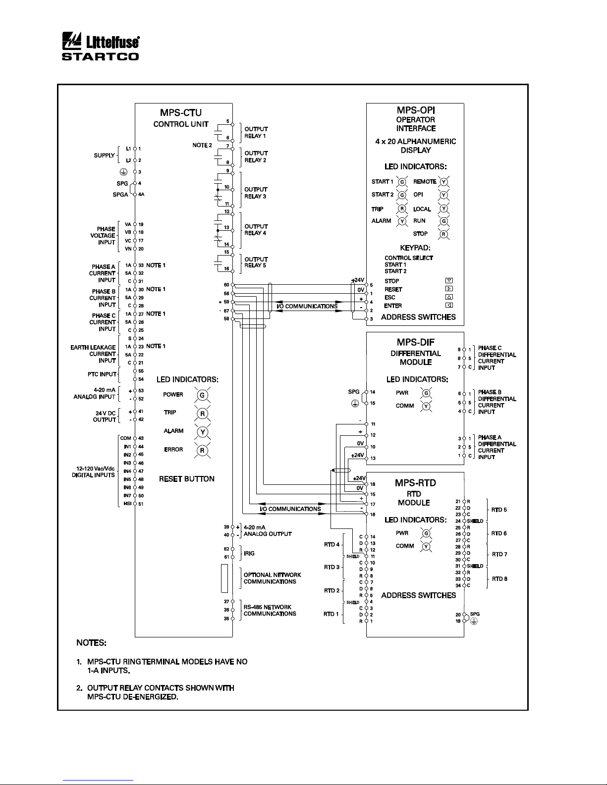
CTU’s flash memory. The MPS block diagram is shown
in Fig. 1.1.
1.2 MPS FEATURES
1.2.1 PROTECTION
• Overload (49, 51)
• Overcurrent (50, 51)
• Earth fault (50G/N, 51G/N)
• Unbalance (voltage and current) (46, 47)
• Phase loss (voltage and current) (46, 47)
• Phase reverse (voltage and current) (46, 47)
• Jam
• Undercurrent (37)
• Failure to accelerate
• Underspeed (14)
• Overvoltage (59)
• Undervoltage (27)
• Underpower (37)
• Reversepower (32)
• Power factor (55)
• Overfrequency (81)
• Underfrequency (81)
• PTC overtemperature (49)
• RTD temperature (38, 49)
• Starts per Hour (66)
• Differential (87)
1.2.2 CONTROL—STARTING METHODS
(1)
• Non-reversing
• Reversing
• Soft start
• Soft start with bypass
• Adjustable-speed drive
• Two speed
• Wye-delta (open or closed transition)
• Reactor (open or closed transition)
• Resistor (open or closed transition)
• Autotransformer
• Part winding
• Slip ring
• Two winding
• Double delta
(1)
Only three CT’s required for all starting methods.
1.2.3 METERING
• Line currents
• Current unbalance
• Positive-sequence current
• Negative-sequence current
• Earth-leakage current
• Differential currents
• Line-to-line voltages
• Line frequency
• Voltage unbalance
• Positive-sequence voltage
• Negative-sequence voltage
• Power
§ Apparent, Reactive, Real, and Power factor
• Energy
§ kWh, kVAh, and kVARh
• Used thermal capacity
• Thermal trend
• Motor speed
• RTD temperatures
• Analog input and output
1.2.4 DATA LOGGING
• Sixty-four records
§ Date and time of event
§ Event type
§ Line currents
§ Current unbalance
§ Earth-leakage current
§ Differential currents
§ Line-to-line voltages
§ Voltage unbalance
§ Thermal capacity
§ Thermal capacity used during starts
§ Start time
§ Analog-input value
§ Frequency
§ Power (P, S, Q, PF)
§ RTD temperatures
§ Trip counters
§ Running hours
§ Waveform Capture
§ 5 seconds of pre-trip waveform data
§ 16 samples per cycle
§ COMTRADE and CSV file generation
1.2.5 INPUTS AND OUTPUTS
• Three ac-current inputs
• Three ac-voltage inputs
• Earth-leakage-current input
• Seven programmable digital (ac/dc) inputs
• 24-Vdc source for digital inputs
• Tachometer (high-speed pulse) input
• 4-20-mA analog input
• 4-20-mA analog output
• PTC thermistor temperature input
Page 8

Page 1-2
MPS Motor Protection System Rev. 6-F-022117
Introduction
• Up to twenty-four RTD inputs
• Five programmable output relays
• Network communications
• IRIG-B time-code input
1.2.6 MPS-OPI OPERATOR INTERFACE
• 4 x 20 vacuum-fluorescent display
• Starter-control keys
• Display-control and programming keys
• LED status indication
• Remote operation up to 1.2 km (4,000’)
• Powered by MPS-CTU
1.2.7 MPS-RTD MODULE
• Eight inputs per module
• Individually selectable RTD types
• RTD Voting
• Solid-state multiplexing
• Up to three modules per system
• Remote operation up to 1.2 km (4,000’)
• Powered by MPS-CTU
1.2.8 MPS-DIF DIFFERENTIAL MODULE
• 3-CT core-balance connection
• 6-CT summation connection
• Remote operation up to 1.2 km (4,000’)
• Powered by MPS-CTU
1.2.9 COMMUNICATIONS INTERFACE
The standard network communication interface is an
RS-485 port with Modbus® RTU and A-B® DF1 protocol
support. In addition to the standard interface, network
communication options include DeviceNet™, Profibus®,
Modbus® TCP, and Ethernet/IP.
1.3 ORDERING INFORMATION
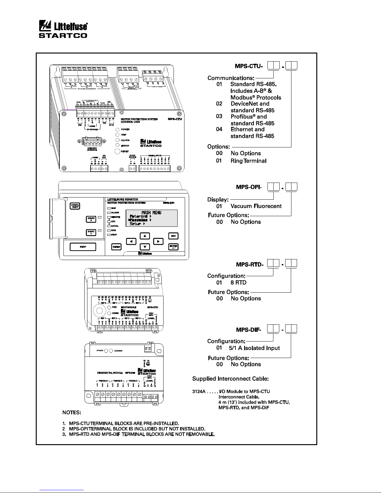
See Fig. 1.2 for MPS-CTU, MPS-OPI, MPS-RTD, and
MPS-DIF model numbers.
Earth-Fault Current Sensors:
EFCT-1 ......................... Earth-Fault CT,
5-A-primary rating,
82 mm (3.2”) window
EFCT-1FC ..................... Flux Conditioner for EFCT-1,
70 mm (2.7”) window
EFCT-2 ......................... Earth-Fault CT with
Flux Conditioner,
5-A-primary rating,
139 mm (5.5”) window
EFCT-26 ....................... Earth-Fault CT,
5-A-primary rating,
26 mm (1”) window
(All EFCT’s include 6 m (19.5’) of 22 AWG (0.33 mm2)
shielded cable.)
SE-CS30-4 ............................. Current Sensor,
30-A-primary rating,
c/w Flux Conditioner,
95.0 mm (3.7”) window
SE-CS30-5 ............................. Current Sensor,
30-A-primary rating,
c/w Flux Conditioner,
130.0 mm (5.1”) window
SE-CS30-8 ............................. Current Sensor
30-A-primary rating,
c/w Flux Conditioner,
200.0 mm (7.9”) window
SE-CS30-26 ......................... Current Sensor,
30-A-primary rating,
26 mm (1.0”) window
SE-CS30-70 ......................... Current Sensor,
30-A-primary rating,
70 mm (2.7”) window
Phase CT’s ............................... Protection-Class CT’s,
Contact factory
Accessories:
SE-IP65CVR-M ................... Hinged Transparent OPI
Cover
SE-485-PP ............................ Port-Powered Serial
Converter
SE-485-DIN ......................... Serial Converter,
Industrial, 24 Vdc
Software:
SE-Comm-RIS ..................... PC Communication
Software
(1)
SE-Flash ............................... Firmware Upgrade
Software
(1)
(1)
Available at www.littelfuse.com/relayscontrols.
Page 9
Page 1-3
MPS Motor Protection System Rev. 6-F-022117
Introduction
FIGURE 1.1 Motor Protection System Block Diagram.
Page 10
Page 1-4
MPS Motor Protection System Rev. 6-F-022117
Introduction
FIGURE 1.2 MPS Ordering Information.
Page 11

Page 2-1
MPS Motor Protection System Rev. 6-F-022117
Installation
2. INSTALLATION
2.1 GENERAL
A basic Motor Protection System (MPS) consists of an
MPS-CTU and three customer-supplied current
transformers (CT's) for measuring phase current. For
core-balance earth-fault detection, a 1-A, 5-A, EFCT-1, or
EFCT-2 CT is required. For the optional Ring Terminal
MPS-CTU, the 1-A connection is not available. The
residual phase-CT connection can also be used for earthfault detection. Voltage inputs do not require potential
transformers (PT’s) for system voltages up to 600 Vac.
For RTD-temperature measurement, up to three
MPS-RTD modules can be connected to the MPS-CTU.
For differential protection, an MPS-DIF module can be
connected to the MPS-CTU. The MPS-OPI provides an
operator interface for the MPS.
The MPS power-factor-corrected switch-mode power
supply is rated 65 to 265 Vac and 80 to 275 Vdc.
All modules can be mounted in any orientation.
2.2 MPS-CTU CONTROL UNIT
The Control Unit is configured for surface mounting.
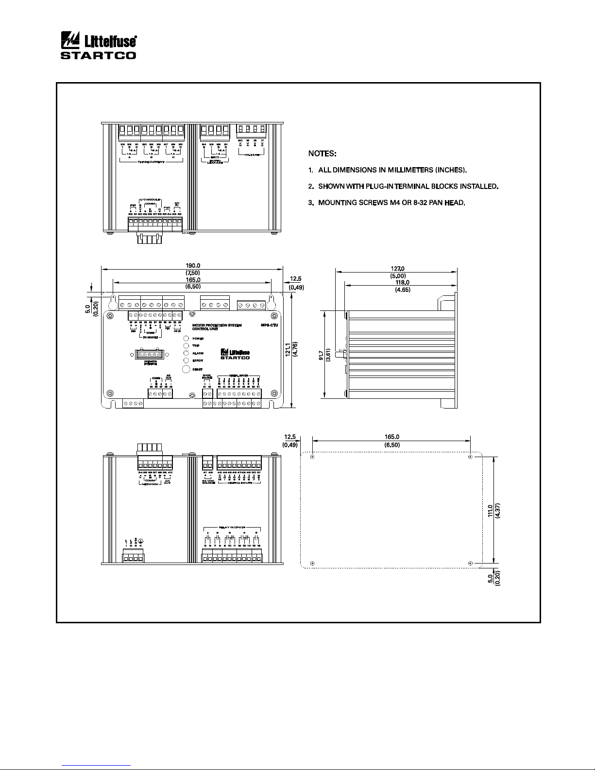
Outline and mounting details for the MPS-CTU are
shown in Figs. 2.1 and 2.1.1.
2.3 MPS-OPI OPERATOR INTERFACE
Outline and mounting details for the MPS-OPI are
shown in Fig. 2.2. It is certified for use in Class I, Zone 2
and Class I, Division 2 hazardous locations.
The Operator Interface is configured for panel
mounting or it can be mounted on the MPS-CTU as
shown in Fig. 2.3. The Operator Interface can also be
mounted on the MPS-CTU ring terminal as shown in
Fig. 2.3.1 (surface mount only).
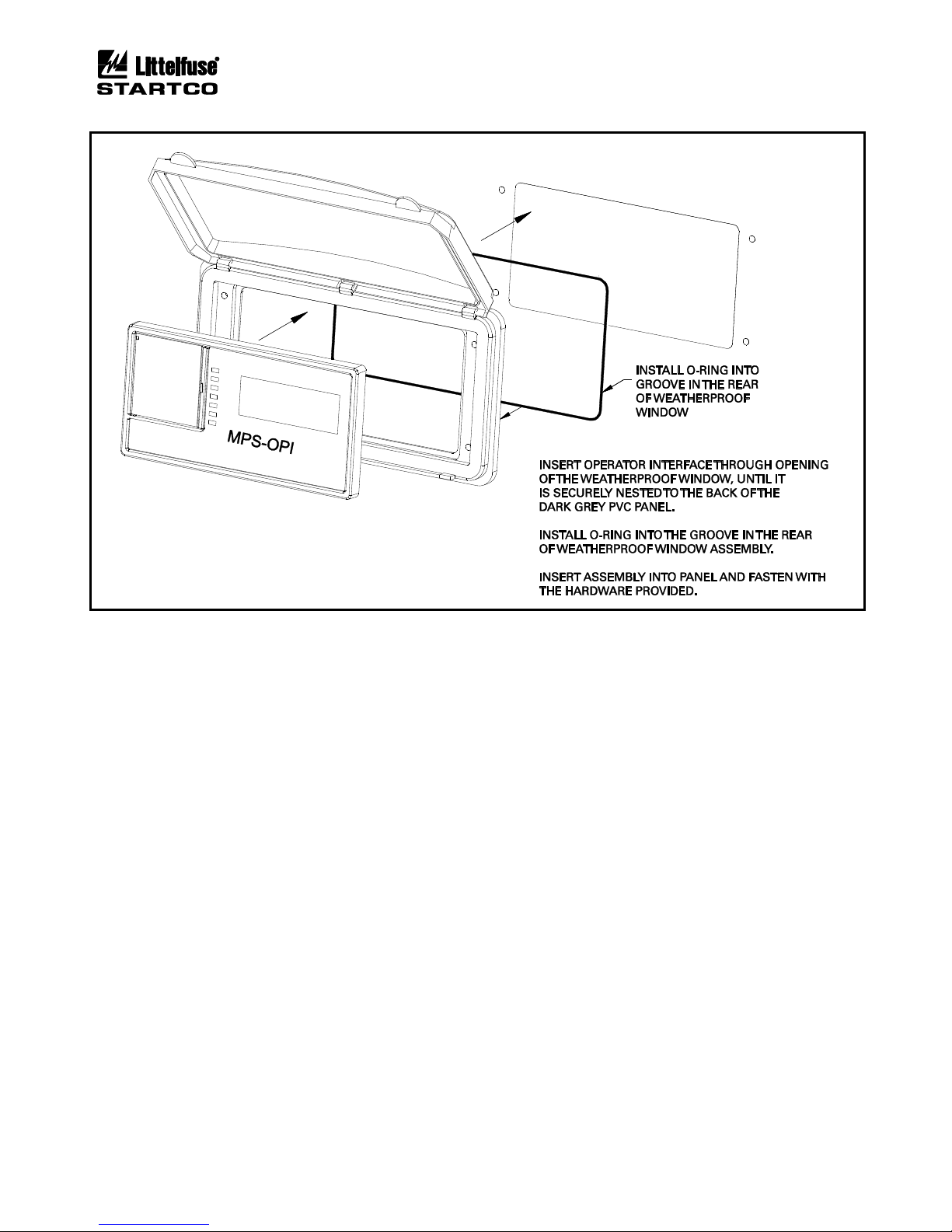
If an optional SE-IP65CVR-M is used, follow the
included installation instructions. See Figs. 2.4 and 2.5.
2.4 MPS-RTD MODULE
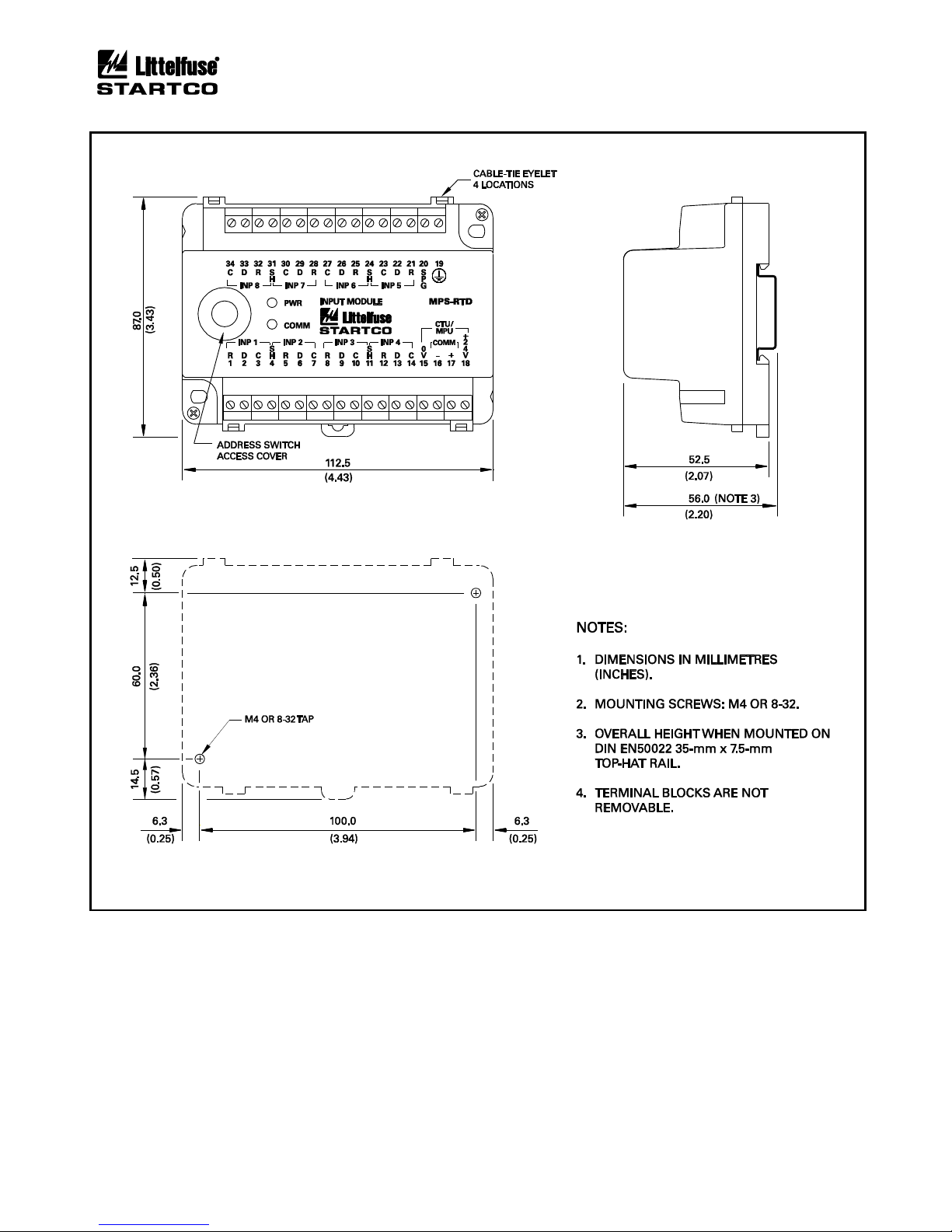
Outline and mounting details for the MPS-RTD are
shown in Fig. 2.6. The MPS-RTD will fit inside most
motor RTD-termination junction boxes and it is certified
for use in Class I, Zone 2 and Class I, Division 2
hazardous locations. The MPS-RTD can be surface or
DIN-rail mounted.
2.5 MPS-DIF DIFFERENTIAL MODULE
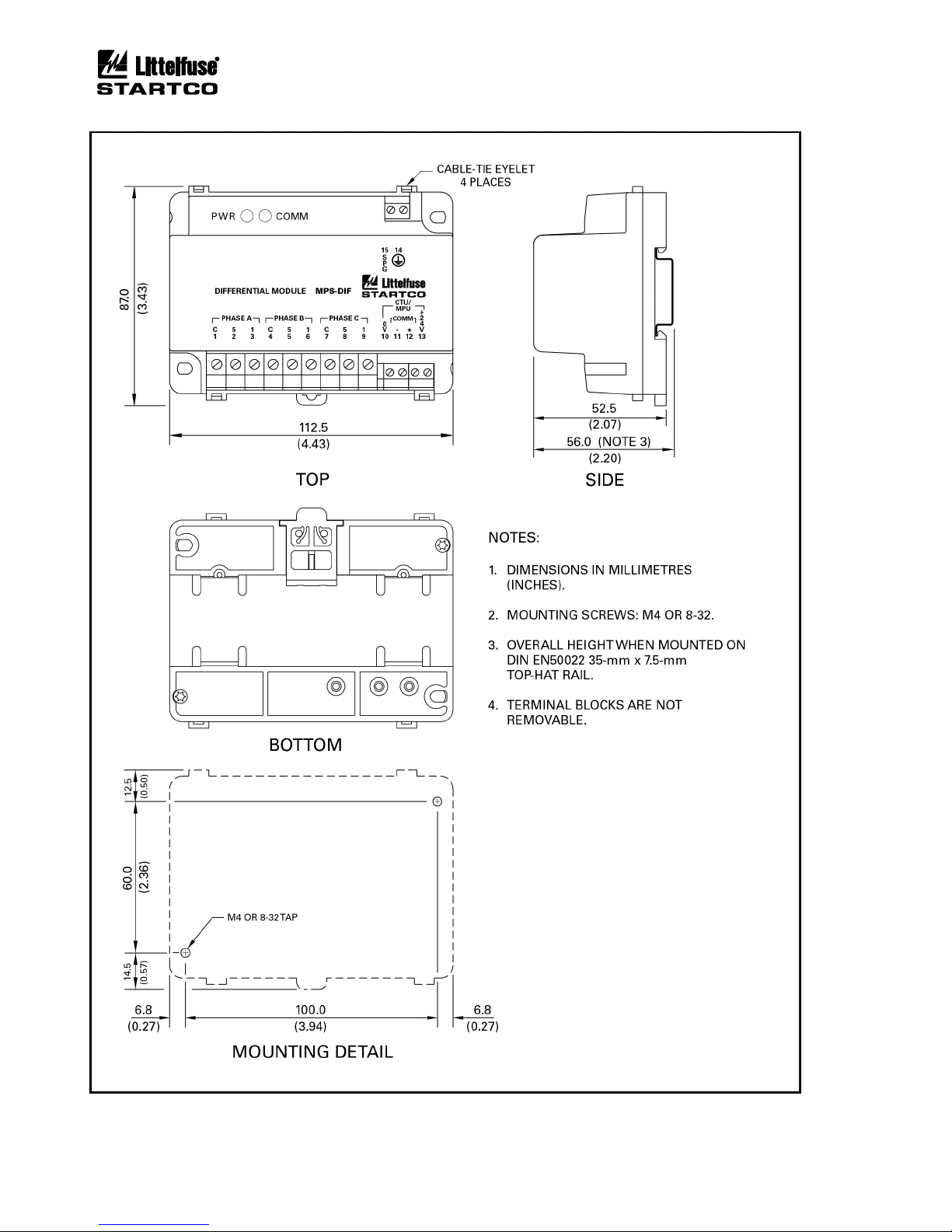
Outline and mounting details for the MPS-DIF are
shown in Fig 2.7. The MPS-DIF can be surface or DINrail mounted.
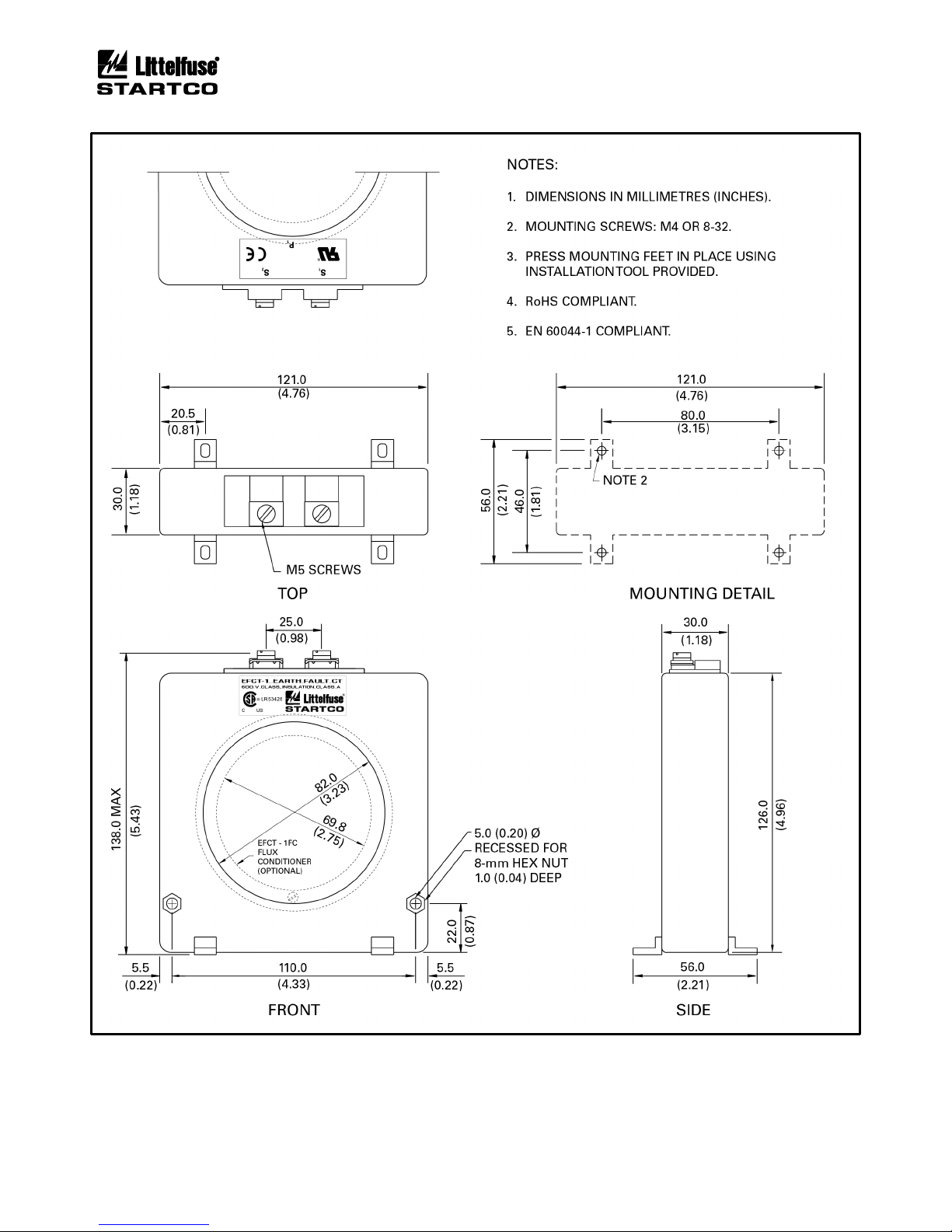
2.6 EARTH-FAULT CT’S
Outline and mounting details for the EFCT-1, EFCT-2,
EFCT-26, and SE-CS30 series are shown in Figs. 2.8, 2.9,
2.10, 2.11, and 2.12.
Page 12
Page 2-2
MPS Motor Protection System Rev. 6-F-022117
Installation
FIGURE 2.1 MPS-CTU Outline and Mounting Details.
Page 13
Page 2-3
MPS Motor Protection System Rev. 6-F-022117
Installation
FIGURE 2.1.1 MPS-CTU-XX-X1 Ring Terminal Outline and Mounting Details.
Page 14

Page 2-4
MPS Motor Protection System Rev. 6-F-022117
Installation
FIGURE 2.2 MPS-OPI Outline and Mounting Details.
Page 15
Page 2-5
MPS Motor Protection System Rev. 6-F-022117
Installation
FIGURE 2.3 MPS-CTU with OPI Outline and Mounting Details.
Page 16
Page 2-6
MPS Motor Protection System Rev. 6-F-022117
Installation
FIGURE 2.3.1 MPS-CTU Ring Terminal with OPI Outline and Mounting Details.
Page 17
Page 2-7
MPS Motor Protection System Rev. 6-F-022117
Installation
FIGURE 2.4 SE-IP65CVR-M Weatherproof Cover Outline.
Page 18
Page 2-8
MPS Motor Protection System Rev. 6-F-022117
Installation
FIGURE 2.5 SE-IP65CVR-M Weatherproof Cover Installation.
Page 19
Page 2-9
MPS Motor Protection System Rev. 6-F-022117
Installation
FIGURE 2.6 MPS-RTD Outline and Mounting Details.
Page 20
Page 2-10
MPS Motor Protection System Rev. 6-F-022117
Installation
FIGURE 2.7 MPS-DIF Outline and Mounting Details.
Page 21
Page 2-11
MPS Motor Protection System Rev. 6-F-022117
Installation
FIGURE 2.8 EFCT-1 Outline and Mounting Details.
Page 22
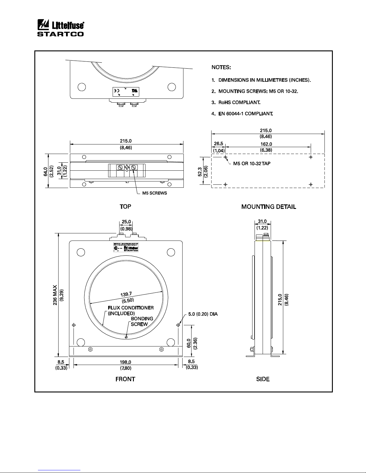
Page 2-12
MPS Motor Protection System Rev. 6-F-022117
Installation
FIGURE 2.9 EFCT-2 Outline and Mounting Details.
Page 23
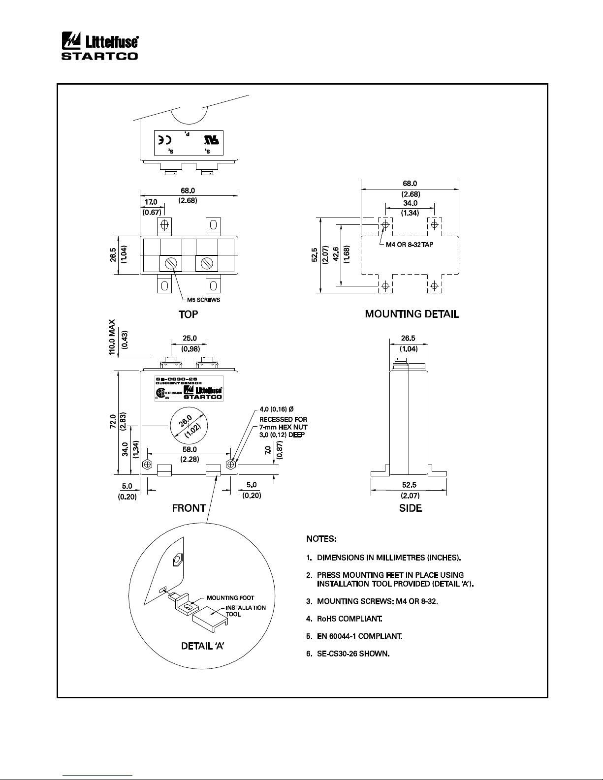
Page 2-13
MPS Motor Protection System Rev. 6-F-022117
Installation
FIGURE 2.10 EFCT-26 and SE-CS30-26 Outline and Mounting Details.
Page 24
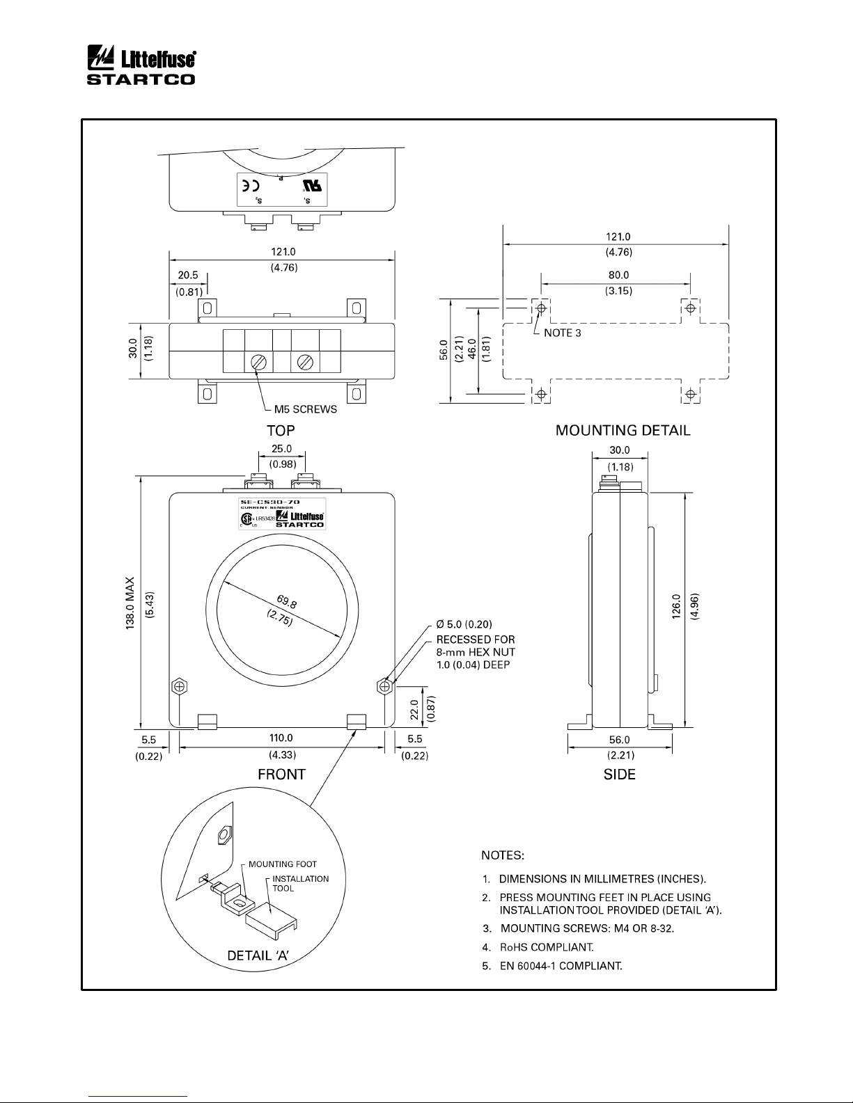
Page 2-14
MPS Motor Protection System Rev. 6-F-022117
Installation
FIGURE 2.11 SE-CS30-70 Outline and Mounting Details.
Page 25
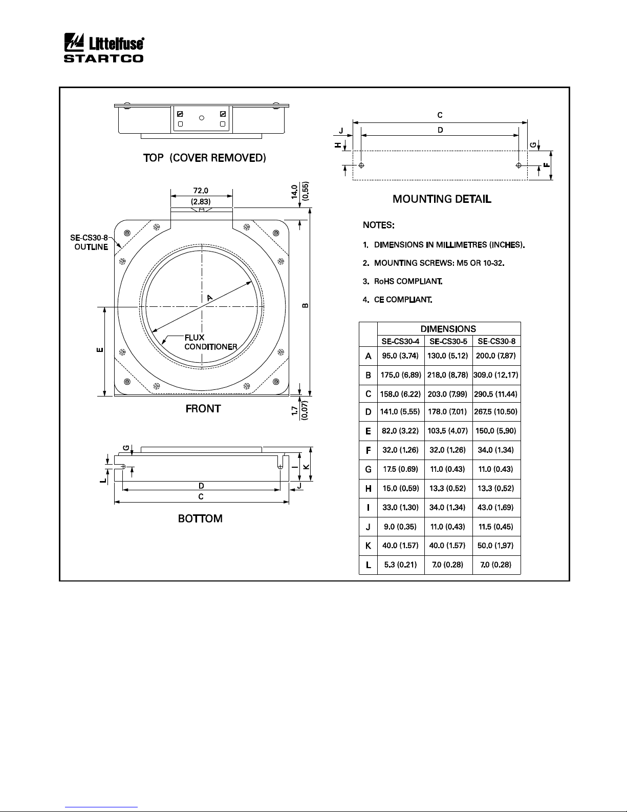
Page 2-15
MPS Motor Protection System Rev. 6-F-022117
Installation
FIGURE 2.12 SE-CS30-4, -5, and -8 Outline and Mounting Details.
Page 26

Page 2-16
MPS Motor Protection System Rev. 6-F-022117
Installation
This page intentionally left blank.
Page 27
Page 3-1
MPS Motor Protection System Rev. 6-F-022117
System Wiring
3. SYSTEM WIRING
3.1 GENERAL
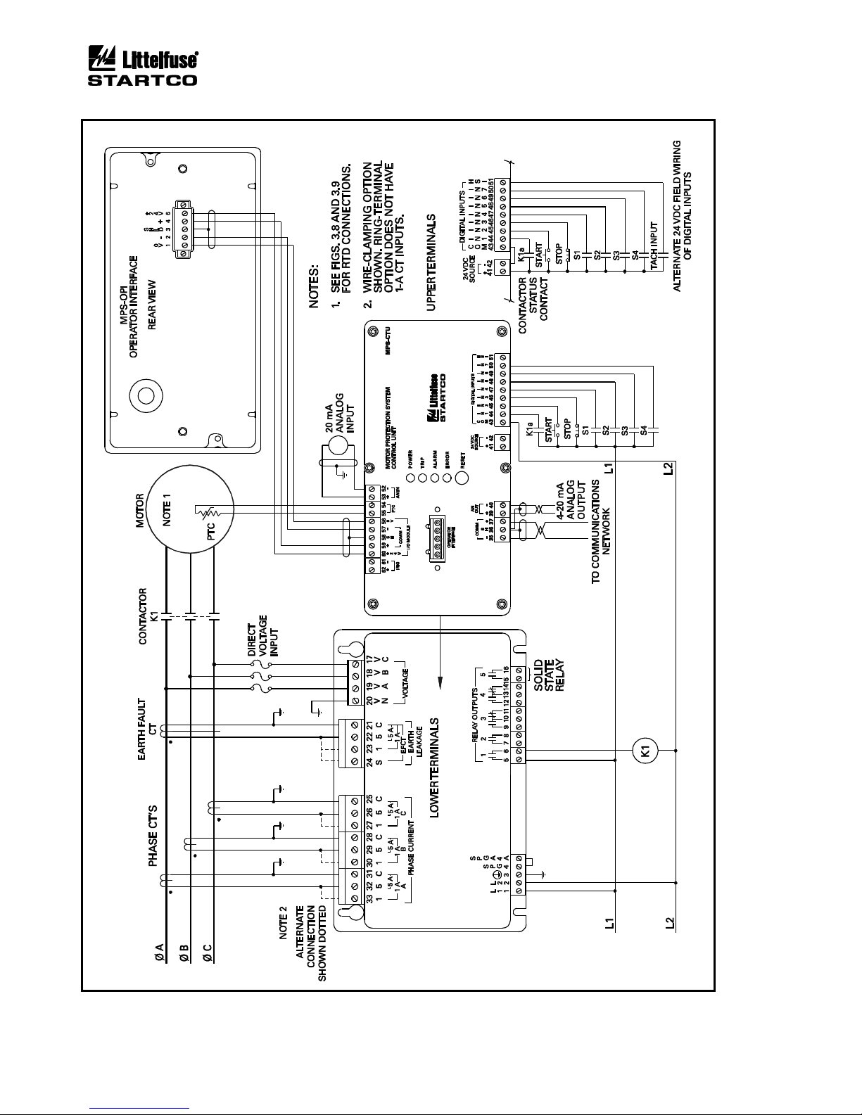
A typical connection diagram is shown in Fig. 3.2. The
MPS-CTU provides the 24-Vdc supply for the peripheral
modules and it communicates with them using an RS-485
interface. The total length of the I/O communication
system must be less than 1.2 km (4,000’). I/O
communications addressing supports up to three modules
of each type; however, the power supply in the MPS-CTU
will not support more than three I/O modules. An
external 24-Vdc power supply is required if more than
three modules are used.
The MPS-CTU voltage inputs can be directly
connected to a system with line-to-line voltages up to
600 Vac. PT's are required for system voltages higher
than 600 Vac. Input resistance of the voltage inputs is
3.4 MΩ.
NOTE: The current and voltage inputs must be phase
sequenced A-B-C with correct polarity observed.
START1, START2, and STOP starter-control
commands can be issued through the digital inputs, the
network interface, or the MPS-OPI. Start, stop, and
interlock contacts can be wired to any of the
programmable digital inputs. The five programmable
output relays can be used for starting control, protection,
and interlock functions. Relay 5 is a solid-state, low-level
output relay not recommended for starter control. See
Section 9 for relay ratings.
NOTE: The default configuration has no assignments for
digital inputs and relay outputs.
3.2 WIRING CONNECTIONS
3.2.1 MPS-CTU CONNECTIONS
The MPS-CTU CT-input terminal blocks accept 22 to
10 AWG (0.3 to 4.0 mm2) conductors. The remaining
MPS-CTU clamping blocks accept 24 to 12 AWG
(0.2 to 2.5 mm2) conductors. Terminal blocks unplug to
allow the MPS-CTU to be easily replaced.
The MPS-CTU Ring Terminal CT-input terminal block
accept a maximum ring width of 8 mm (0.315”). These
terminal blocks cannot be unplugged.
3.2.1.1 SUPPLY VOLTAGE
Derive supply voltage from the line side of the motor
controller or from an independent source. Connect supply
voltage to terminals 1 and 2 (L1 and L2) as shown in
Fig. 3.2. In 120-Vac systems, L2 is usually designated as
the neutral conductor. For direct-current power supplies,
use L1 for the positive terminal and L2 as the negative
terminal. Earth terminal 3 ( ).
Internal surge-protection devices are connected to
terminals 4 (SPG) and 4A (SPGA) to allow dielectricstrength testing. Terminals 4 and 4A must be connected
except during dielectric-strength testing.
The 24-Vdc I/O module supply (terminals 56 and 60)
can support three I/O modules. An external 24-Vdc
supply is required if more than three modules are used.
3.2.1.2 CURRENT INPUTS
The MPS-CTU uses 1-A or 5-A CT’s for phase-current
measurement. The MPS-CTU Ring Terminal uses 5-A
CT’s for phase-current measurement. To maintain
specified accuracy, phase CT’s should be protection class
and selected with a primary rating between 100 and 300%
of motor full-load current (FLA). Current threshold is a
function of full-load current and CT-primary rating as
defined by the following formula.
The Current Threshold is also used to determine when
the motor is in Run mode. Several protective functions
are only enabled when in Run mode. See Section 5.1 for
a description of Run mode.
For synchronous-motor applications, the CT-primary
rating should be selected such that the current threshold is
less than the idle current, typically less than 5%. All CT
inputs can withstand a common-mode voltage of 120 Vac
so that the MPS-CTU can be connected in series with
other CT loads. The connection diagram in Fig. 3.2
shows a typical connection where the MPS-CTU is the
only device connected to the phase CT's. The MPS-CTU
requires the phase sequence to be A-B-C with correct
polarity.
The Ip Threshold sets the current level where unbalance
protection becomes active. See Section 5.8.
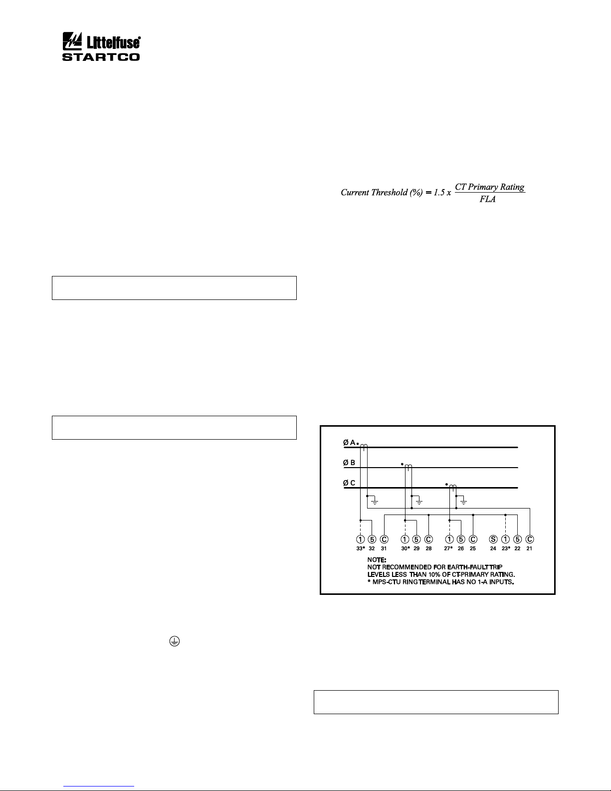
A 1-A, 5-A, or sensitive CT is used for core-balance
earth-leakage measurement. The MPS-CTU Ring
Terminal has no 1-A input. See Fig. 3.1 for the phase-CT
residual connection for earth-fault detection.
FIGURE 3.1 Residual Phase-CT Connection.
3.2.1.3 VOLTAGE INPUTS
For all input-voltage connections, the MPS-CTU
requires the phase sequence to be A-B-C with correct
polarity.
If voltage inputs are not used, connect VA, VB, and
VC to VN.
NOTE: A voltage input is required for line-frequency
metering.
Page 28
Page 3-2
MPS Motor Protection System Rev. 6-F-022117
System Wiring
FIGURE 3.2 Typical MPS Connection Diagram.
Page 29
Page 3-3
MPS Motor Protection System Rev. 6-F-022117
System Wiring
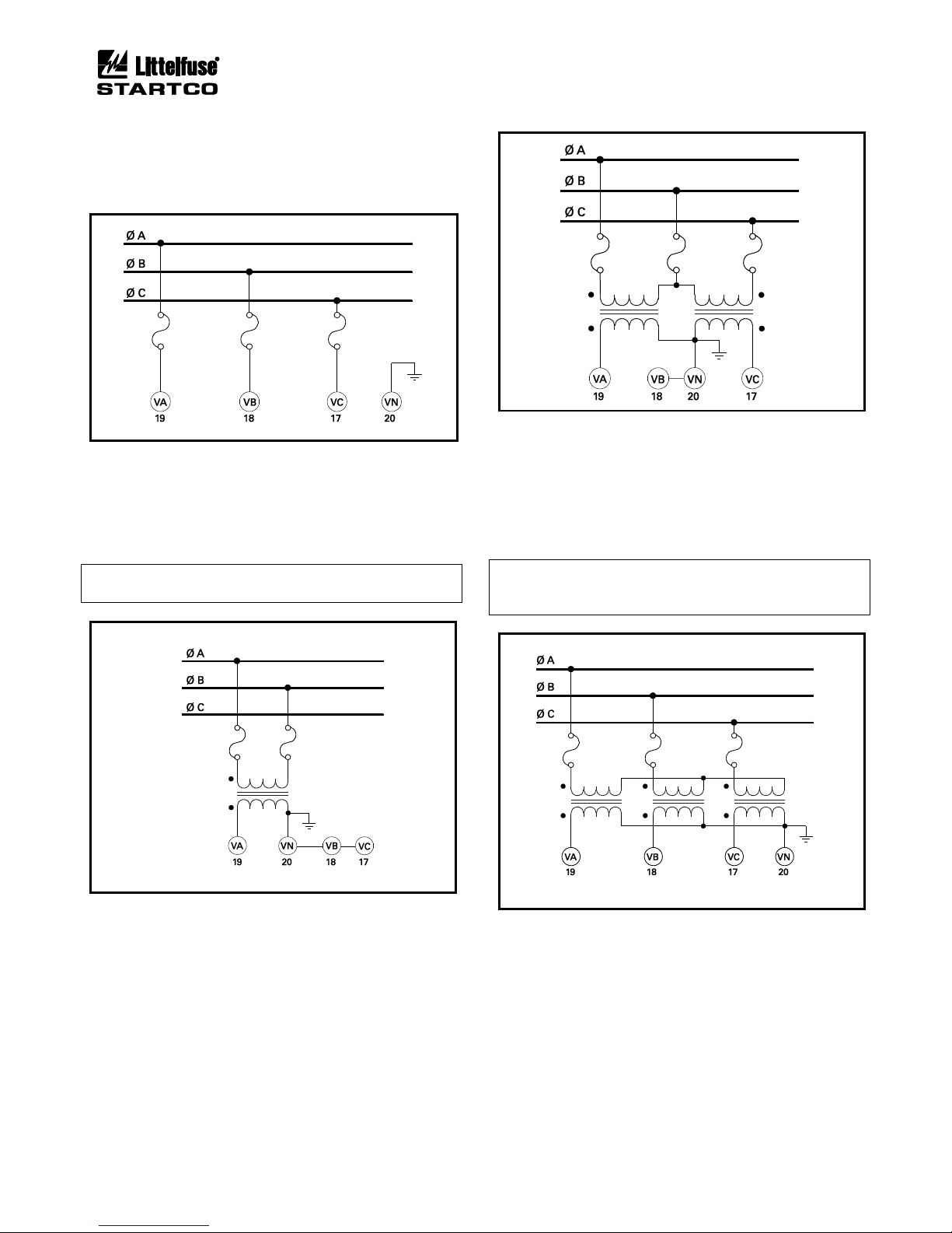
3.2.1.3.1 DIRECT CONNECTION
PT's are not required for system voltages up to 600 Vac
line-to-line. Connect the voltage inputs as shown in
Figs. 3.2 and 3.3.
FIGURE 3.3 Direct Connection.
3.2.1.3.2 1-PT CONNECTION
The 1-PT connection is shown in Fig. 3.4. Connect the
PT between phase A and phase B. The PT-secondary
voltage must be less than 350 Vac.
NOTE: The 1-PT connection does not allow detection of
voltage unbalance.
FIGURE 3.4 1-PT Connection.
3.2.1.3.3 2-PT CONNECTION
The 2-PT connection is shown in Fig. 3.5. The PTsecondary voltages must be less than 350 Vac. Connect
the PT secondaries in open delta.
FIGURE 3.5 2-PT Connection.
3.2.1.3.4 3-PT CONNECTION
The 3-PT connection is shown in Fig. 3.6. The PTsecondary voltages must be less than 350 Vac. Since the
MPS-CTU measures line-to-line voltage, there is no
advantage in using a 3-PT connection over a 2-PT
connection.
NOTE: This connection relies on PT primarymagnetization current for voltage balance. Do not
connect any other secondary loads.
FIGURE 3.6 3-PT Connection.
3.2.1.4 DIGITAL INPUTS
Digital inputs 1 to 8 (terminals 44 to 51) are referenced
to COM (terminal 43). These inputs are isolated from all
other terminals and operate over a 12 to 120 Vac/Vdc
range. Inputs 1 to 7 have programmable functions. See
Table 4.2. Input 8 is a high-speed input (HSI) for a
tachometer sensor.
Page 30
Page 3-4
MPS Motor Protection System Rev. 6-F-022117
System Wiring
3.2.1.4.1 DC OPERATION
Supply voltage for dc-input operation can be obtained
from the 24-Vdc source (terminals 41 and 42), or it can be
obtained from an external 12- to 120-Vdc supply.
The internal source is current limited at 100 mA and is
referenced to the analog output (terminal 40) and the I/O
Supply (terminal 56). Connect the “−” terminal of the dc
source to COM and connect field inputs between “+” and
the digital-input terminals.
3.2.1.4.2 AC OPERATION
Inputs operate over a 12- to 120-Vac range. Connect
the ac neutral to COM and connect field inputs between
line and the digital inputs.
3.2.1.4.3 COMBINED AC AND DC OPERATION
If both ac and dc inputs are used, connect both the acsupply common and dc-supply “−” to COM.
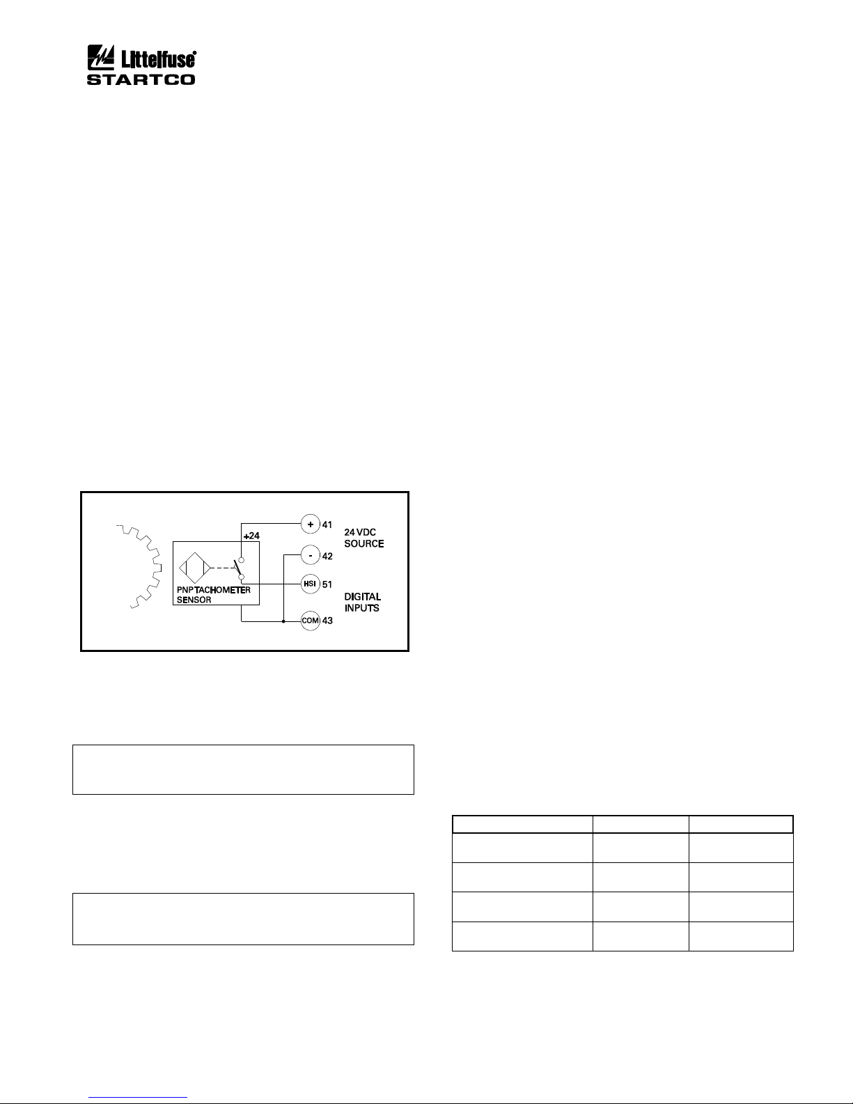
3.2.1.4.4 TACHOMETER INPUT (HSI)
A tachometer sensor can be used to provide motorspeed measurement. Connect a logic-output PNP
tachometer as shown in Fig. 3.7.
FIGURE 3.7 Digital Tachometer Input (HSI).
3.2.1.5 ANALOG INPUT (AN IN)
The analog input (terminal 52 and 53) is a 4-20-mA
current input with a 100-Ω input impedance.
NOTE: The analog input is referenced to an internal
supply with 100-kΩ resistors. Maximum common-mode
voltage is ± 5 Vdc with respect to MPS-CTU terminal 4.
3.2.1.6 ANALOG OUTPUT (AN OUT)
The analog output is a self-powered current-source
output. The current source output is the “+” (terminal 39)
and the common is “−” (terminal 40).
NOTE: The analog output (terminal 40) is internally
referenced to the 24-Vdc source (terminal 42) and the I/O
supply (terminal 56).
3.2.1.7 PTC INPUT
Terminals 54 and 55 are provided for PTC overtemperature protection. See Section 9 for specifications.
3.2.1.8 IRIG-B INPUT
Terminals 61 and 62 are used for an IRIG-B time-code
signal. When an IRIG-B signal is detected, the real-time
clock (RTC) synchronizes with it. The user must set the
MPS date value because the IRIG-B day-of-the-year
parameter is not supported.
If the time-code generator does not have a local-time
adjustment, the IRIG Offset set points can be used to
adjust the hour and minute values so that the MPS will
read local time.
3.2.1.9 I/O MODULE COMMUNICATION
The I/O module communications interface (terminals
56 through 60) is used to support optional modules. The
connector labeled Operator Interface on the MPS-CTU
top panel is in parallel with terminals 50 to 56. It is used
for direct MPS-OPI mounting. See Section 2.3.
I/O module communication is based on the 2-wire
multi-drop RS-485 standard. Overall line length must not
exceed 1.2 km (4,000’). For line lengths exceeding
10 m (33’), 150-Ω terminations are required at the cable
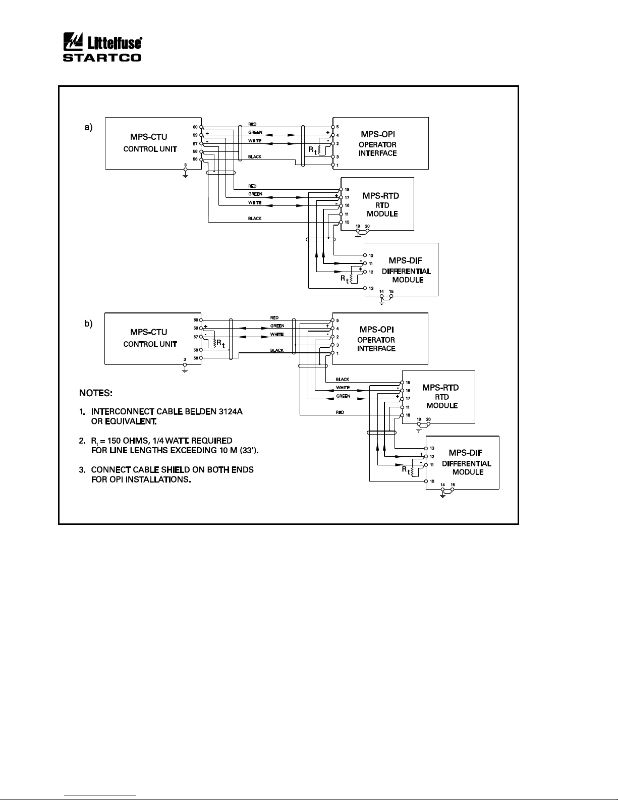
ends. See Fig. 3.9.
3.2.1.10 RS-485 NETWORK COMMUNICATIONS
Terminals 35, 36, and 37 are used for the standard
RS-485 interface. See Section 4.2.15.
3.2.2 MPS-OPI CONNECTIONS AND ADDRESS SELECTION
Connect the MPS-OPI to the MPS-CTU using shielded
cable (Belden® 3124A or equivalent). The 24-Vdc supply
for the MPS-OPI is provided by the MPS-CTU. The
cable shield must be connected at both ends so that
MPS-OPI transient protection is operational. See Fig. 3.9.
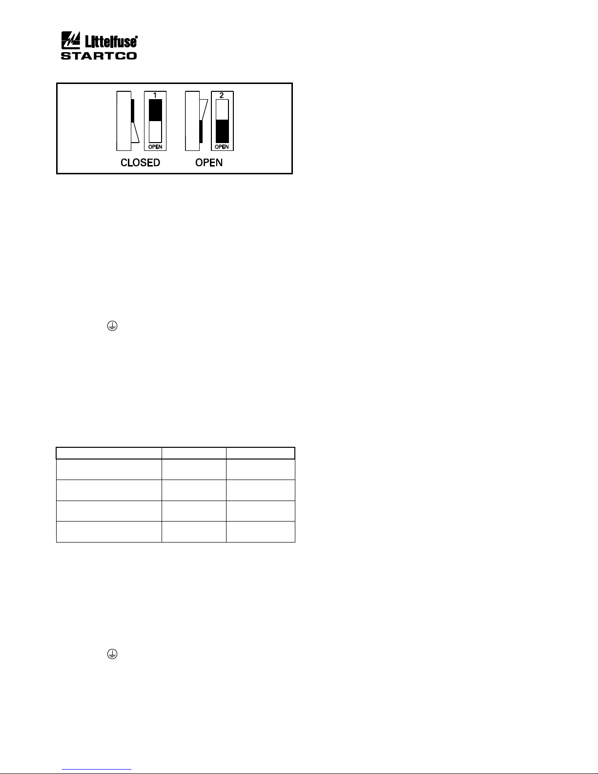
The MPS-OPI has two switches to select its network
address. See Figs. 2.2 and 3.8. Up to three MPS-OPI
modules can be connected to the I/O MODULE bus, and
each active OPI must have a unique address. If one OPI
is used, address 1 must be used. If two OPI's are used,
addresses 1 and 2 must be used. If three OPI's are used,
addresses 1, 2, and 3 must be used.
Table 3.1 and Fig. 3.8 shows the addressing selection
format.
TABLE 3.1 MPS-OPI ADDRESS SELECTION
ADDRESS
SWITCH 1
SWITCH 2
0
(Factory Test)
Open
Open
1
(First OPI)
Closed
Open
2
(Second OPI)
Open
Closed
3
(Third OPI)
Closed
Closed
Page 31
Page 3-5
MPS Motor Protection System Rev. 6-F-022117
System Wiring
FIGURE 3.8 Address Selection Switch Detail.
3.2.3 MPS-RTD CONNECTIONS AND ADDRESS SELECTION
MPS-RTD terminal blocks accept 24 to 12 AWG
(0.2 to 2.5 mm2) conductors.
Connect the MPS-RTD to the MPS-CTU using the
four-conductor shielded cable (Belden 3124A or
equivalent) as shown in Fig. 3.9. The MPS-CTU 24-Vdc
supply can power up to three MPS-RTD modules.
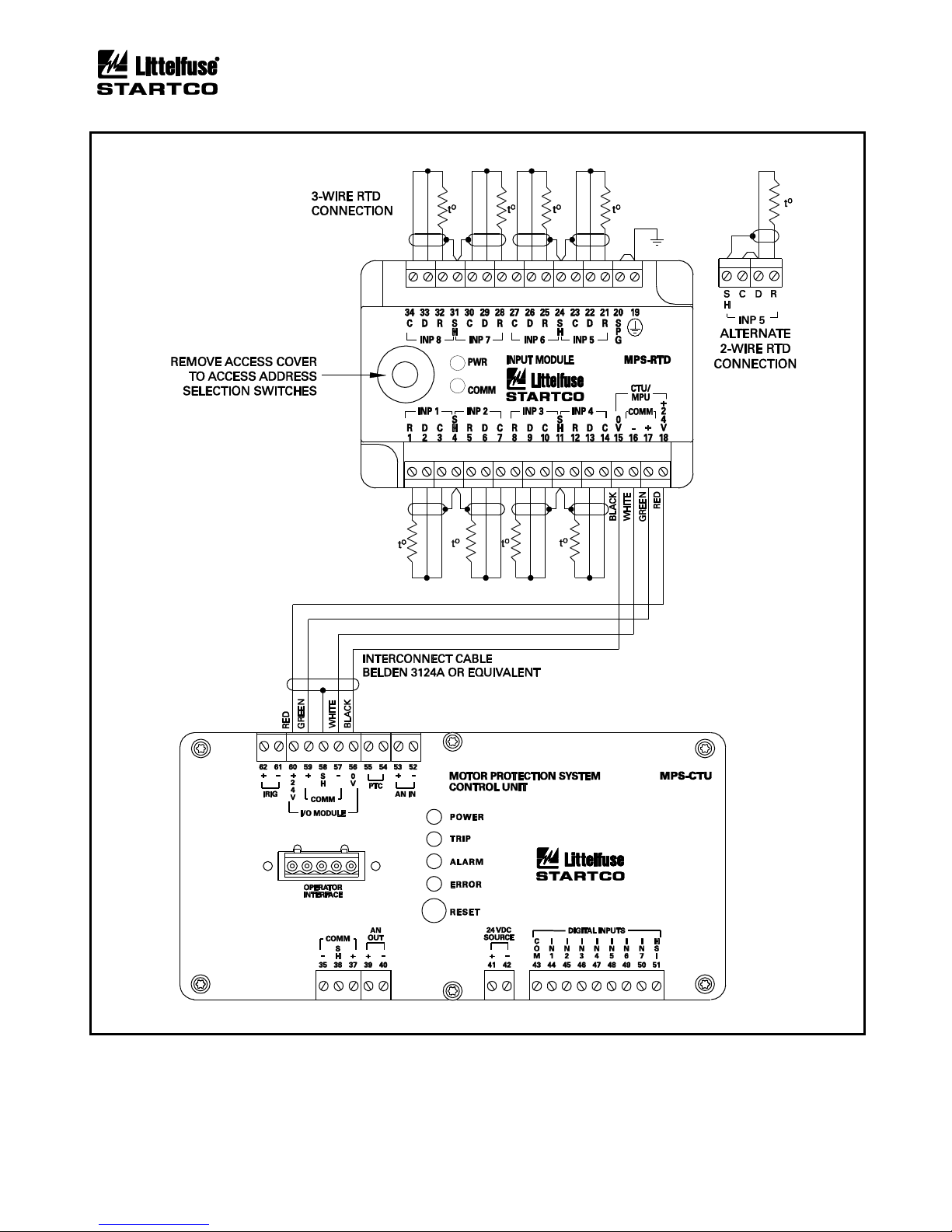
Connect RTD’s to the MPS-RTD as shown in Fig 3.9.
When the RTD module is installed in a motor junction
box, RTD-lead shielding is not required.
Connect the surge-protection (SPG) terminal 20 to
terminal 19 ( ), and earth terminal 19.
The MPS-RTD has two switches to select its network
address. See Figs. 3.8 and 3.10. Up to three MPS-RTD
modules can be connected to the I/O MODULE bus, and
each RTD-module address must be unique. If one module
is used, address 1 must be used. If two RTD modules are
used, addresses 1 and 2 must be used. If three RTD
modules are used, addresses 1, 2, and 3 must be used.
Table 3.2 shows the addressing selection format.
TABLE 3.2 MPS-RTD ADDRESS SELECTION
ADDRESS
SWITCH 1
SWITCH 2
0
(Offline)
Open
Open
1
(First RTD Module)
Closed
Open
2
(Second RTD Module)
Open
Closed
3
(Third RTD Module)
Closed
Closed
3.2.4 MPS-DIF CONNECTIONS
The MPS-DIF CT-input terminal blocks accept 22 to
10 AWG (0.3 to 4.0 mm2) conductors. The remaining
MPS-DIF clamping blocks accept 24 to 12 AWG (0.2 to
2.5 mm2) conductors.
Connect the MPS-DIF to the MPS-CTU using fourconductor shielded cable (Belden 3124A or equivalent) as
shown in Fig. 3.9.
Connect the surge-protection (SPG) terminal 15 to
terminal 14 ( ), and earth terminal 14.
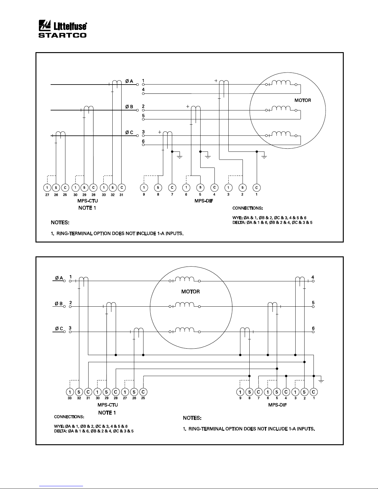
3.2.4.1 CORE BALANCE
The core-balance connection is shown in Fig. 3.11. To
minimize power-cable and CT-lead length, both the
differential CT’s and the MPS-DIF can be located near
the motor. The primary rating of the differential CT does
not have to match the phase-CT primary rating and is
usually selected with a lower ratio resulting in more
sensitive differential protection. The core-balance
method avoids CT-matching issues and is the preferred
connection.
3.2.4.2 MPS SUMMATION
The MPS summation connection uses three phase CT’s
and three differential CT’s as shown in Fig. 3.12. Both
CT ratio and CT-saturation characteristics must be
matched to avoid differential currents under motor
starting and running conditions. The MPS-DIF module
should be located near the MPS-CTU to minimize CT
wire length. It is preferred to use three dedicated phase
CT’s and three core-balance differential CT’s as
described in Section 3.2.4.1.
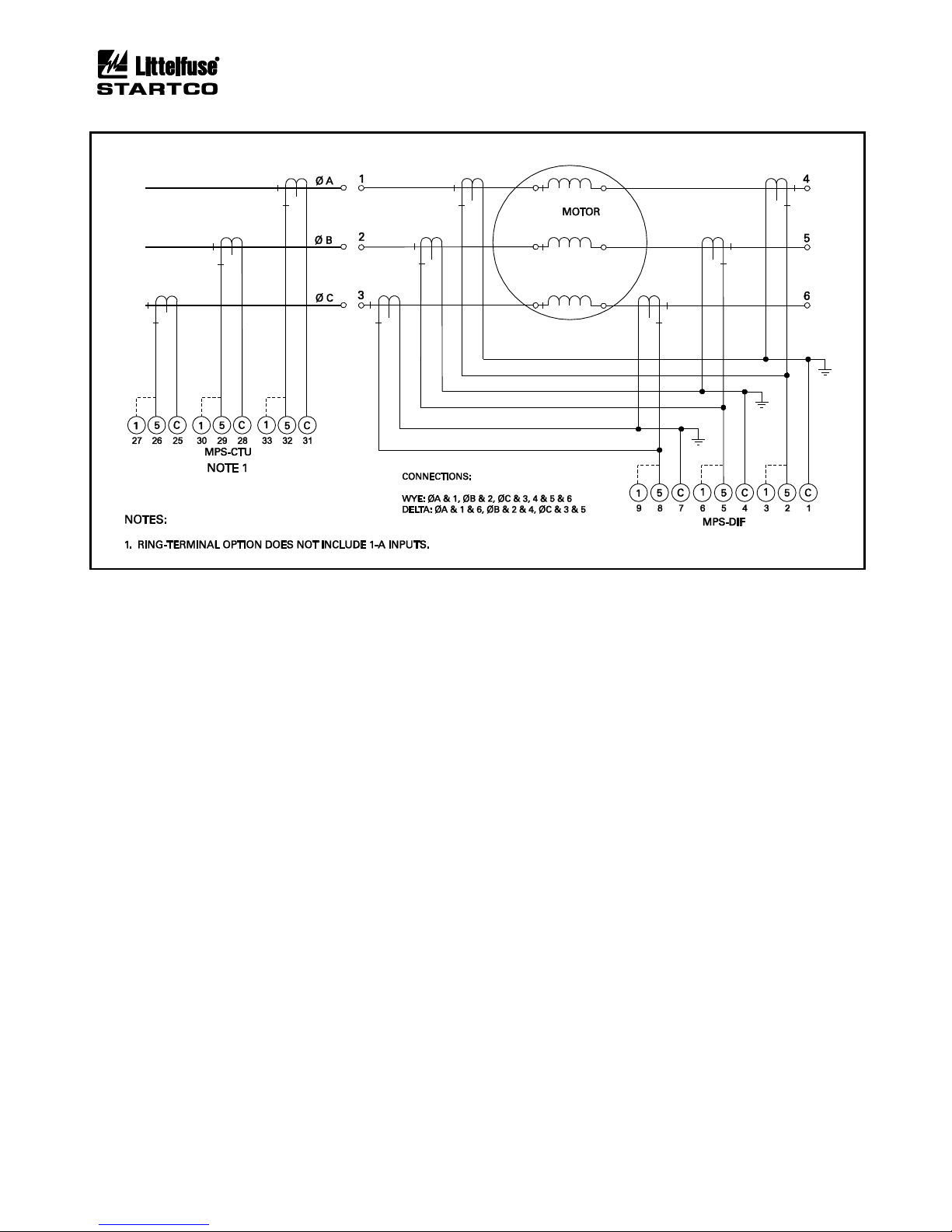
For the delta connection, the MPS FLA Rating is set
equal to the motor’s full-load current multiplied by √3.
Power, power factor and energy measurements are not
correct for the delta connection.
3.2.4.3 DIF SUMMATION
The DIF summation connection uses six differential
CT’s as shown in Fig. 3.13. Both CT-ratio and CTsaturation characteristics must be matched to avoid
differential currents under motor starting and running
conditions. It is preferred to use three core-balance CT’s
as described in Section 3.2.4.1. This six CT connection
allows the CT’s and MPS-DIF to be placed near the motor
to minimize power-cable and CT-lead length.
3.2.5 DIELECTRIC-STRENGTH TESTING
Dielectric-strength testing should be performed only on
CT inputs, PT inputs, output relays, and digital inputs.
Unplug all other I/O and remove the SPG connection
(terminal 4 to terminal 4A) on the MPS-CTU during
dielectric-strength testing.
Page 32
Page 3-6
MPS Motor Protection System Rev. 6-F-022117
System Wiring
FIGURE 3.9 Two Examples of I/O Module Connections.
Page 33
Page 3-7
MPS Motor Protection System Rev. 6-F-022117
System Wiring
FIGURE 3.10 MPS-RTD Connection Diagram.
Page 34
Page 3-8
MPS Motor Protection System Rev. 6-F-022117
System Wiring
FIGURE 3.11 Core Balance Connection.
FIGURE 3.12 MPS Summation Connection.
Page 35
Page 3-9
MPS Motor Protection System Rev. 6-F-022117
System Wiring
FIGURE 3.13 DIF Summation Connection.
Page 36

Page 3-10
MPS Motor Protection System Rev. 6-F-022117
System Wiring
This page intentionally left blank.
Page 37
Page 4-1
MPS Motor Protection System Rev. 6-F-022117
Operation and Setup
4. OPERATION AND SETUP
4.1 GENERAL
The MPS-CTU can operate independently. It can also
operate in conjunction with network communications, the
MPS-OPI, MPS-RTD and the MPS-DIF. All settings are
stored in the MPS-CTU and can be accessed using the
OPI or the network communications interface. Use
SE-Comm-RIS software and an SE-485PP or SE-485-DIN
serial converter to program with a personal computer.
In the following sections, menu items and setup
parameters are listed in italics and are shown in the format
displayed on the OPI. The OPI cannot display subscripts
and superscripts.
Menu selection is in the following format:
Menu 1 | Sub Menu 1 | Sub Menu 2 | Sub Menu 3 |……
Example: For the menu item shown in Fig. 4.1, the
notation is Setup | System Ratings | CT Primary
Metering 4
Messages 4
5Setup4
Protection4
vSystem Ratings4
Starter4
6CT Primary→
•
EF-CT-Primary→
•
System Voltage→
•
Input Voltage→
•
•
•
FIGURE 4.1 Menu Example.
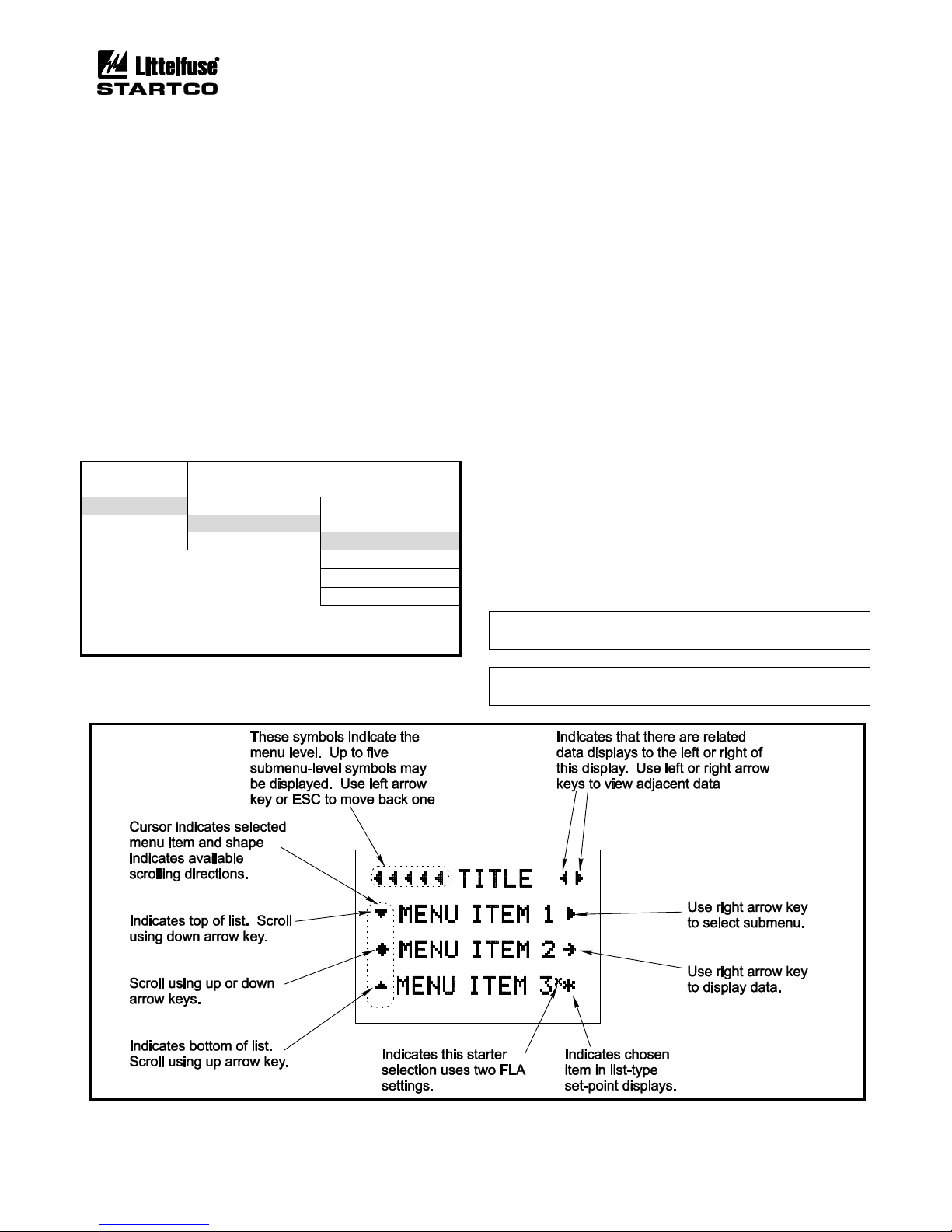
Fig. 4.2 shows the symbols that assist in navigating the
menu system and how these symbols relate to the arrow
keys on the MPS-OPI. See the menu map in Appendix A.
4.2 MPS-CTU
4.2.1 LED INDICATION
The four LED’s on the MPS-CTU indicate POWER
(green), TRIP (red), ALARM (yellow), and ERROR
(red). The POWER LED is ON when supply voltage is
present. The TRIP and ALARM LED’s indicate a trip or
alarm condition. The ERROR LED is ON during
firmware updates or when there is an MPS-CTU failure.
4.2.2 RESET SWITCH
The reset switch is used to simultaneously reset all
trips. Trips cannot be held off by a maintained closure.
4.2.3 PHASE-CT INPUTS
OPI Menu: Setup | System Ratings | CT Primary
The setting range for the CT-primary rating is 1 to
5,000 A. To maintain specified accuracy, phase CT’s
should be selected with a primary rating between 100 and
300% of motor full-load current.
Current unbalance will indicate “−” if the current
sequence is B-A-C. If B-A-C sequence is indicated,
correct the CT connections so that power measurements
will be valid.
NOTE: B-A-C sequence will cause a trip if current phasereverse protection is enabled.
NOTE: Phase-unbalance and phase-loss testing requires
three-phase inputs to the MPS.
FIGURE 4.2 Menu Symbols.
Page 38
Page 4-2
MPS Motor Protection System Rev. 6-F-022117
Operation and Setup
4.2.4 EARTH-FAULT-CT INPUT
OPI Menu: Setup | System Ratings | EF-CT Primary
The setting range for the earth-fault-CT-primary rating
is 1 to 5,000 A. The CT-primary rating is 5 A for
sensitive CT’s—EFCT-1 and EFCT-2.
4.2.5 VOLTAGE INPUTS
OPI Menu: Setup | System Ratings
Select the voltage-connection type (1 PT line-line, 2 PT
line-line, 3 PT line-neutral/direct) to enable voltagemeasuring functions. System Voltage is the system lineto-line voltage. The system voltage range is 120 V to
25 kV. For the 1-PT and 2-PT connections, Input Voltage
is the PT-secondary voltage when system voltage is
applied. For the 3-PT connection, the Input Voltage is the
PT-secondary line-to-line voltage. For the direct
connection, set Input Voltage the same as the System
Voltage setting. In all cases, line-to-line voltages are
displayed.
Voltage unbalance will indicate “−” if the voltage
sequence is B-A-C. If B-A-C sequence is indicated,
correct the PT connections so that power measurements
will be valid.
NOTE: The 1-PT connection does not allow detection of
voltage unbalance.
NOTE: B-A-C sequence will cause a trip if voltage
phase-reverse protection is enabled.
4.2.6 MOTOR DATA
OPI Menu: Setup | System Ratings
OPI Menu: Setup | Protection ⏐ Overload
Motor data must be entered for the FLA Rating,
Frequency, and Service Factor. If a tachometer is used,
the Sync Speed is required. If the starter selected requires
two FLA ratings, FLA Rating 2 must be entered.
The Frequency setting determines the sampling rate
used by the MPS for current and voltage measurements.
If Sync to ASD is selected as the analog-input type, the
Frequency setting is not used and the analog output from
an adjustable-speed drive determines the sampling rate
used by current- and voltage-measuring algorithms. See
Section 5.29.2.
Locked-rotor current, cold locked-rotor time, and hot
locked-rotor time must be entered in the Protection |
Overload menu to provide customized overload
protection. See Section 5.2.
4.2.7 OUTPUT RELAY ASSIGNMENT
OPI Menu: Setup | Relay Outputs | Relay x
Each of the five output relays can be assigned to one of
the functions listed in Table 4.1. More than one relay can
be assigned the same function. Note that Relay 5 is a
solid-state relay with a low current rating and should only
be used for interlocks or annunciation.
Relay assignments Starter RLYA, Starter RLYB, Starter
RLYC, and Starter RLYD operate in conjunction with
MPS starting functions to control the motor-starter
contactor(s). See Section 6. Contactor status can be
monitored using auxiliary contacts and the digital inputs.
See Section 4.2.8 and Figs. 6.9 to 6.23.
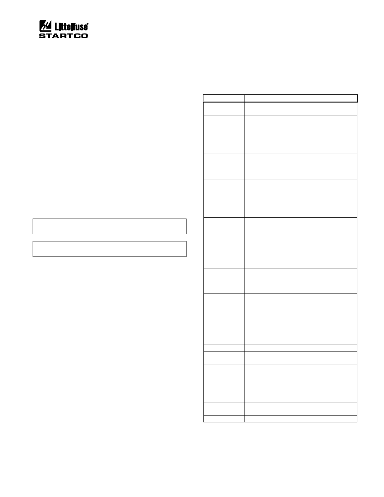
TABLE 4.1 OUTPUT-RELAY FUNCTIONS
FUNCTION
ASSIGNMENT OR ACTION
Starter RLYA
Relay is assigned to the Starter Relay A
function.
Starter RLYB
Relay is assigned to the Starter Relay B
function.
Starter RLYC
Relay is assigned to the Starter Relay C
function.
Starter RLYD
Relay is assigned to the Starter Relay D
function.
Trip1
Relay operates when a trip occurs in a
protective function assigned Trip1, Trip1&2,
Trip1&3, or Trip1,2,&3. Fail-safe or non-failsafe mode selection is active.
Trip1 Pulse
(1)
Trip1 energizes the relay for the time duration
specified by the RY Pulse Time set point.
Trip2
Relay operates when a trip occurs in a
protective function assigned Trip2, Trip1&2,
Trip2&3, or Trip1,2,&3. Fail-safe or non-failsafe mode selection is active.
Trip3
Relay operates when a trip occurs in a
protective function assigned Trip3, Trip1&3,
Trip2&3, or Trip1,2,&3. Fail-safe or non-failsafe mode selection is active.
Alarm1
Relay operates when an alarm occurs in a
protective function assigned Alarm1,
Alarm1&2, Alarm1&3, or Alarm1,2,&3. Failsafe or non-fail-safe mode selection is active.
Alarm2
Relay operates when an alarm occurs in a
protective function assigned Alarm2,
Alarm1&2, Alarm2&3, or Alarm1,2,&3. Failsafe or non-fail-safe mode selection is active.
Alarm3
Relay operates when an alarm occurs in a
protective function assigned Alarm3,
Alarm1&3, Alarm2&3, or Alarm1,2,&3. Failsafe or non-fail-safe mode selection is active.
Local
Relay energized when Local starter control is
selected.
Interlock
Relay is energized when all digital-input
interlocks are completed.
Current
Relay is energized when current is detected.
Run Mode
Relay is energized when motor is running.
(Current <125% for Run-Mode Delay)
Sequence
Complete
Relay is energized when the starter
Start Time has elapsed.
Start Inhibit
Relay is energized when in an I2t or
starts-per-hour inhibit condition.
Watchdog
Relay is energized when the supply voltage is
applied and the MPS is operating properly.
Reduced OC
Relay is energized when in maintenance mode
(ROC = On).
None
(2)
No Assignment (Default).
(1)
Assign this function to only one relay. Non-fail-
safe operation only.
(2)
Relay outputs must be assigned. Default is None.
Page 39
Page 4-3
MPS Motor Protection System Rev. 6-F-022117
Operation and Setup
When a trip occurs, all assigned starter-control relays
(Starter RLYA to Starter RLYD) are de-energized and
relays assigned the Trip1, Trip2, or Trip3 function
operate. The trip signal may originate from a protective
function, from a digital input assigned the Trip1 function,
or from a communications network command. See
Sections 4.2.8 and 6.
Relays assigned to trip or alarm functions operate in
fail-safe or non-fail-safe mode. Set the mode using the
Setup ⏐ Relay Outputs ⏐ Relay x ⏐ Mode menu.
Except for overload trips, which can be selected to
auto-reset, trips must be reset with an MPS-OPI, a digital
input, or a network command. A trip cannot be reset
when the trip condition is present.
When a protective function issues an alarm, relays
assigned to the corresponding Alarm1, Alarm2, or
Alarm3 function operate. Alarms auto-reset when the
alarm condition is corrected.
Relays assigned the Interlock function energize when
all digital inputs assigned the Interlock function are valid
(voltage detected at digital input).
4.2.8 DIGITAL INPUTS 1 TO 7
OPI Menu: Setup | Digital Inputs | Digital Input x |
Input x Function
OPI Menu: Setup | Digital Inputs | Digital Input x |
In x Start Bypass
OPI Menu: Setup | Digital Inputs | Digital Input x |
In x Bypass Delay
OPI Menu: Setup | Digital Inputs | Digital Input x |
In x Trip Delay
Each digital input can be assigned to one of the
functions listed in Table 4.2. More than one digital input
can be assigned the same function.
Start inputs are not active when Protection Only is
selected as the starter type. The STOP function is always
active. In Protection Only mode, STOP initiates a Trip1
signal.
Each digital input assigned the Trip1 function has Start
Bypass, Bypass Delay, and Trip Delay set points. When
Start Bypass is enabled, the Trip1 function is bypassed
during a start for the duration specified by Bypass Delay.
Since start detection is based on motor current, this
feature can be used in the Protection Only mode. After
the Bypass Delay, the Trip1 function is enabled and a trip
occurs if the digital-input voltage is removed for the time
specified by the Trip Delay. If Start Bypass is disabled,
Bypass Delay is not used and the Trip1 function is always
enabled. The bypass feature can be used in pump-control
applications to allow time for a pressure switch to close.
Reset inputs are “one-shot” resets that require a
transition from open to closed. Maintaining a reset switch
closure does not inhibit trips.
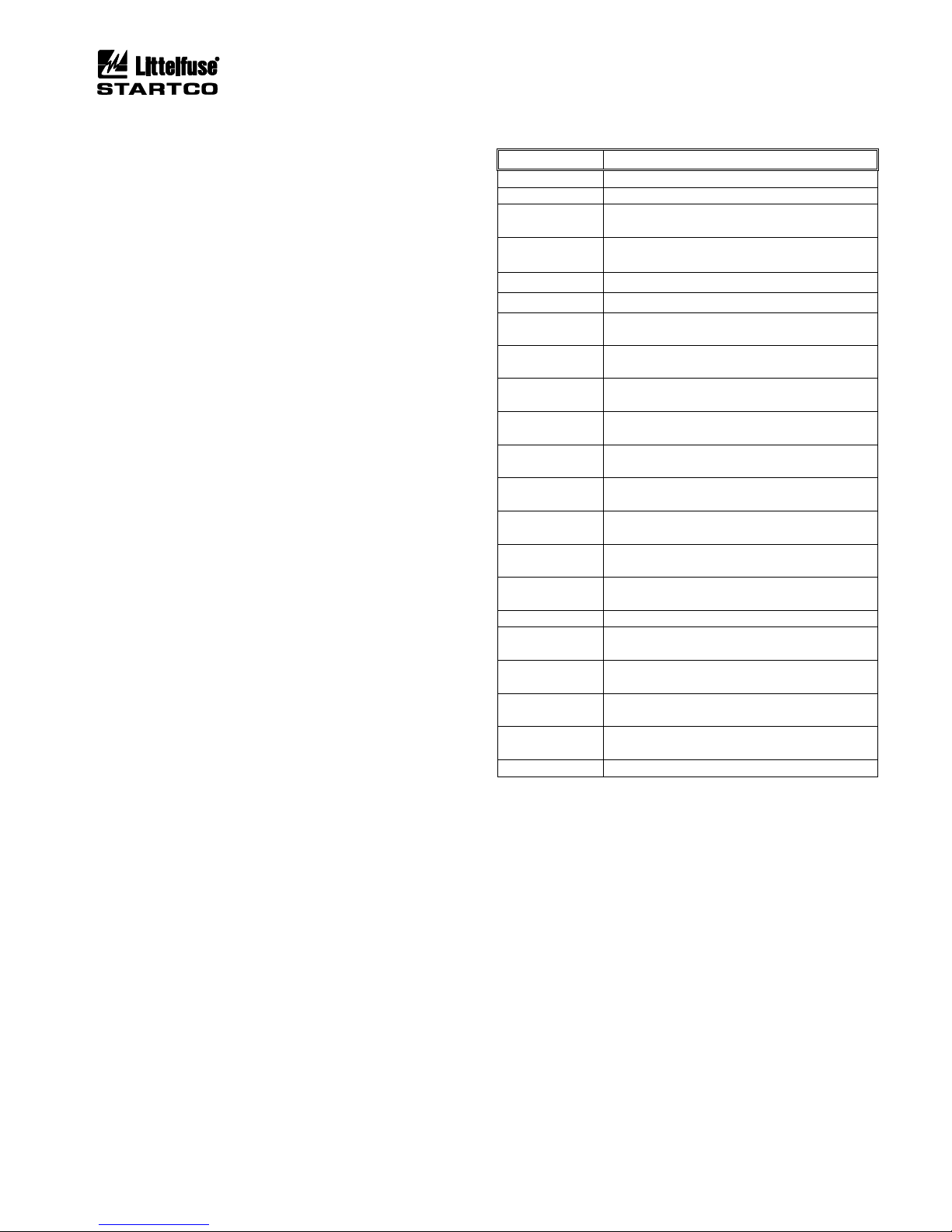
TABLE 4.2 DIGITAL-INPUT FUNCTIONS
FUNCTION
STATE
(1)
Start1
1 = Start1 (Momentary)
Start2
1 = Start2 (Momentary)
Local Select -
1 = Per CONTROL SELECT Setting
0 = Local Control
Local Select +
0 = Local Control
(2)
1 = Per CONTROL SELECT Setting
Local Start1
(2)
1 = Start1 (Momentary)
Local Start2
(2)
1 = Start2 (Momentary)
2-Wire Start1
1 = Start1 (Maintained)
0 = Stop
2-Wire Start2
1 = Start2 (Maintained)
0 = Stop
Stop
1 = Start Allowed
0 = Stop
RLYA Status
1 = Contactor Closed
0 = Contactor Open
RLYB Status
1 = Contactor Closed
0 = Contactor Open
RLYC Status
1 = Contactor Closed
0 = Contactor Open
RLYD Status
1 = Contactor Closed
0 = Contactor Open
Interlock
1 = Start Allowed (If all interlocks are valid.)
0 = Start Not Allowed
Trip1
1 = No Trip1
0 = Trip1 (Delays Selectable)
Reset
1 = Reset Trips
FLA2 Select
(3)
1 = Select FLA2
0 = Select FLA1
Limit1 Stop
1 = Start1 Allowed
0 = Start1 Stop
Limit2 Stop
1 = Start2 Allowed
0 = Start2 Stop
Reduced OC
1 = Reduced OC Set Point Not Operational
0 = Reduced OC Set Point Operational
None
No Assignment (Default)
(1)
1 = Input voltage applied, 0 = Input voltage not
applied.
(2)
Interlocks bypassed in LOCAL.
(3)
Applies only to Protection Only mode.
LOCAL is selected using the OPI, the digital input,
or by network communications. The Local Select source
is responsible for de-selecting. For example if both the
digital input and the network communications select
LOCAL, both must also de-select LOCAL. The Local
Select – and Local Select + selections allow the digital
input to select LOCAL control. Both positive and
negative logic versions allow implementation of various
“Hand-Off-Auto” control schemes. See Section 6 for
CONTROL SELECT operation.
In applications where MPS starter functions are not
used, FLA2 Select can be used to switch between FLA1
and FLA2. This applies only to Protection Only mode.
The selected FLA is displayed in the Metering ⏐ System
State menu.
Page 40
Page 4-4
MPS Motor Protection System Rev. 6-F-022117
Operation and Setup
Limit1 Stop and Limit2 Stop are limit-switch inputs
typically used with reversing starters. Limit1 Stop is a
stop input associated with Start1 and Limit2 Stop is a stop
input associated with Start2.
The Reduced OC selection operates in conjunction with
the reduced overcurrent set point which must be enabled.
See Section 5.5.
When Reduced OC is selected and no digital input
voltage is applied, the reduced overcurrent set point is
operational. When digital input voltage is applied, the
reduced overcurrent set point is not operational.
The following rules apply when multiple inputs are
assigned the same function:
• Start1, Start2, Local Start1, and Local Start2:
Momentary voltage on any input will initiate a start.
(MPS must be in LOCAL for Local Start1 and Local
Start2 operation.)
• Stop: Voltage must be present on all inputs to allow
an MPS-controlled start.
• Interlock: Voltage must be present on all inputs to
allow an MPS-controlled start and to energize an
interlock output relay. Digital inputs programmed as
Interlock are bypassed in LOCAL. Interlocks must
remain valid while the motor is running.
• RLYA, RLYB, RLYC, and RLYD Status: Voltage
applied to any input programmed for a contactor
status results in contactor-closed status.
• Reset: Voltage applied to any input will reset trips.
• 2-Wire Start1 and 2-Wire Start2: Voltage on any
input will initiate a start. All inputs must be open for
a stop.
• FLA2 Select: Voltage on one or more inputs assigned
to FLA2 Select will select FLA2.
4.2.9 TACHOMETER INPUT (HSI)
OPI Menu: Setup | System Ratings | Sync Speed
OPI Menu: Setup | Digital Inputs | Tachometer
This input is provided for connection to a 24-Vdc
proximity sensor for speed measurement. Set the number
of pulses per revolution and enable the High-Speed Input
in the Tachometer menu. Pulse-frequency range is 10 Hz
to 10 kHz. These two settings are required for RPM
readings.
If Failure to Accelerate protection is used, set the
motor’s synchronous speed in the Sync Speed menu. To
fully utilize a speed-setting range from 10 to 100%, a fullspeed frequency of at least 100 Hz is required.
The MPS averages 16 pulse periods to determine
speed.
4.2.10 ANALOG OUTPUT
OPI Menu: Setup | Analog Output | Output Parameter
A 25-mA programmable current output is provided on
the CTU. Analog-output parameters are shown in
Table 4.3.
Factory calibration is 4-20 mA. If calibration is
required, use the Analog Output menus.
Zero Calibration:
• Select Zero in the Output Parameter menu.
• Measure the output current and adjust the Zero
Calibrate setting for the desired output. The
calibration number for 4 mA will be in the range of
100 to 110.
Full-Scale Calibration:
• Select Full Scale in the Output Parameter menu.
• Measure the output current and adjust the
FS Calibrate setting for the desired output. The
calibration number for 20 mA will be in the range of
540 to 550.
Calibration numbers are not changed when factory
defaults are loaded.
TABLE 4.3 ANALOG-OUTPUT PARAMETERS
PARAMETER
FULL SCALE
COMMENTS
Phase Current
PH-CT-Primary Rating
Maximum of 3 Phases
Earth Leakage
EFCT-Primary Rating
Differential Current
DF-CT-Primary Rating
Maximum of 3 Currents
Used I2t Capacity
100% I2t
Stator Temperature
(1)
200°C (392°F)
Maximum of Stator RTD’s
Bearing Temperature
(1)
200°C (392°F)
Maximum of Bearing RTD’s
Load Temperature
(1)
200°C (392°F)
Maximum of Load RTD’s
Ambient Temperature
(1)
200°C (392°F)
Maximum of Ambient RTD’s
Voltage
System Voltage
Maximum Line-to-Line Voltage
Unbalance (I)
1.0 per unit or 100%
I2/I1
Power Factor
1.0
Absolute Value
Real Power
CT Primary × System Voltage × √3
Absolute Value
Reactive Power
CT Primary × System Voltage × √3
Absolute Value
Apparent Power
CT Primary × System Voltage × √3
Absolute Value
Zero
Not Applicable
Used for Zero Calibration
Full Scale
Not Applicable
Used for Full-Scale Calibration
Speed
Synchronous Speed
(1)
Output range is 0 to 200°C (32°F to 392°F). The output defaults to the calibrated zero output for an
open or shorted RTD sensor.
Page 41

Page 4-5
MPS Motor Protection System Rev. 6-F-022117
Operation and Setup
4.2.11 ANALOG INPUT
OPI Menu: Setup | 4-20 Analog In | Input Function
The analog input function is selectable as Metering
Only, Protection, Sync to ASD, or Motor Speed.
4.2.11.1 METERING ONLY
OPI Menu: Setup | 4-20 Analog In ⏐ Metering Only
When Metering Only is selected, an analog input does
not affect MPS operation, but its value can be observed in
the Metering menu and with a communications network.
4.2.11.2 PROTECTION
OPI Menu: Setup | 4-20 Analog In ⏐ Protection
The Protection analog input has high- and low-level
trip and alarm set points. A high-level trip or alarm
occurs when the 4-20-mA input exceeds the high-level
trip or alarm set point. A low-level trip or alarm occurs
when the 4-20-mA input is lower than the low-level trip
or alarm set point.
4.2.11.3 SYNCHRONIZE TO ASD
OPI Menu: Setup | 4-20 Analog In ⏐ Sync to ASD
When Sync to ASD is selected the MPS uses the 4-20
mA input to set the internal sampling rate for current and
voltage inputs. Select drive-frequency values
corresponding to 4 and 20 mA.
4.2.11.4 MOTOR SPEED
OPI Menu: Setup | 4-20 Analog In ⏐ Motor Speed
This selection overrides the selections for the high-
speed tachometer input – failure-to-accelerate protection
and speed metering use the analog input as the source of
speed information.
4.2.12 STARTER
OPI Menu: Setup | Starter
As a default, Starter Type is set to Protection Only.
When a starter type is selected, output relays must be
assigned for contactor control. See Section 4.2.7. Digital
inputs must be assigned if contactor-status feedback is
required. See Section 4.2.8.
See Section 6 for starter information.
4.2.13 PROTECTION
OPI Menu: Setup | Protection
OPI Menu: Setup | System Ratings | Run Mode Delay
See Section 5 for protective function details. As a
minimum, locked-rotor current and time must be set for
overload protection.
Some protective functions are active after the Run-
Mode Delay.
4.2.14 MISCELLANEOUS CONFIGURATION
OPI Menu: Setup | System Config
System Name Appears on many of the display
screens and can be set by the user.
(18-character alphanumeric field)
Password Used to change the 4-character
alphanumeric password.
Clock Setting Used to set the date, 24-hour clock,
and IRIG set points. Daylight
savings time is not supported.
Password Timeout Used to set the password time-out
delay. Delay is measured from last
key press.
Maintenance Used to:
• Clear event records, trip
counters, energy values, and run
hours
• Load defaults
• View firmware version and
serial numbers
• Unlock local control if
communication is lost
• Update Firmware
4.2.15 NETWORK COMMUNICATIONS
OPI Menu: Setup ⏐ Hardware ⏐ Network Comms
The standard interface on the MPS is an RS-485
network. Modbus® RTU and A-B® DF1 protocols are
supported.
The protocol, network ID (address), error checking, and
baud rate are selectable. See Appendices C, D, E, and F.
If equipped with an optional network interface, refer to
the appropriate optional communications-interface
manual.
4.3 MPS-OPI
4.3.1 GENERAL
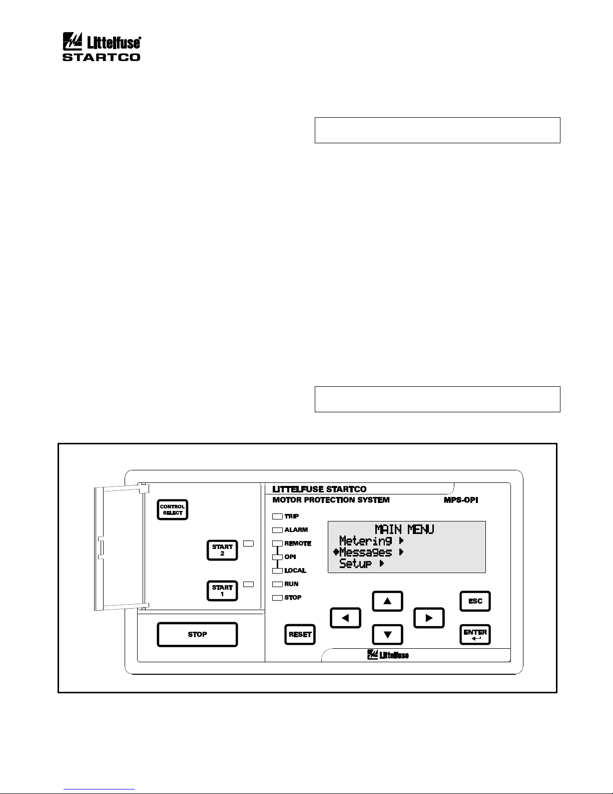
See Fig. 4.3. The Operator Interface (OPI) is used to
perform motor-control functions, display meter readings,
and program the MPS-CTU. Set points are not resident in
the OPI. Control voltage for the MPS-OPI (24 Vdc) is
supplied by the CTU and communications with the CTU
is through an RS-485 link. This allows the MPS-OPI to
be mounted up to 1.2 km (4,000’) from the CTU. Up to
three OPI’s can be used with each CTU.
4.3.2 CONFIGURING THE MPS-CTU FOR OPI
OPERATION
OPI Menu: Setup | Hardware | OPI Display
Select the number of OPI's in the Number of OPI's
menu. The MPS-CTU supports up to three OPI’s. In
multiple-OPI systems, all OPI's display the same
information and the CTU will process key presses from
all OPI's. If an OPI is not used, set number of OPI's to 1
(default).
A loss-of-communication trip can be enabled in the
OPI-Loss Trip menu. Display intensity can be set in the
Intensity menu.
To extend the life of the vacuum-florescent display, a
screen saver is provided and enabled using the Screen
Saver menu. The screen saver activation time is defined
by the Setup | System Config | Password Timeout setting.
Page 42
Page 4-6
MPS Motor Protection System Rev. 6-F-022117
Operation and Setup
4.3.3 STARTER CONTROL
OPI Menu: Setup | Starter | Starter Type
OPI Menu: Setup | Hardware | OPI Display |
OPI Ctrl Select
A starter type other than Protection Only must be
selected for starter functions to become operational.
The OPI has a CONTROL SELECT key and three
yellow LED’s (labeled REMOTE, OPI, and LOCAL) to
select and indicate the start sources that the MPS will
respond to. Each of the start sources can be enabled or
disabled in the OPI Ctrl Select menu, and the CONTROL
SELECT key allows the operator to choose from among
the enabled start sources. The factory default has all
sources enabled and REMOTE selected. Regardless of
the control setting, all stop sources are always enabled.
4.3.3.1 OPI CONTROL
If only the OPI LED is on, the MPS is under OPI
control and start keys on the OPI are the only start source
the MPS will respond to. If the OPI has been enabled as a
start source for remote control, the OPI LED will also be
on when remote control is selected. In this case, the MPS
will also respond to the other sources enabled in remote
control (Remote Group).
4.3.3.2 LOCAL CONTROL
OPI Menu: Setup | Digital Inputs | Digital Input x |
Input x Function
When the LOCAL LED is on, the MPS is under local
control and digital inputs programmed as Local Start 1 or
Local Start 2 are the only start sources the MPS will
respond to.
NOTE: The I2t Start Inhibit function and digital inputs
programmed as Interlock are bypassed in local control.
Local control can also be selected with a network
command or by a digital input programmed for Local
Select—both have priority over the CONTROL SELECT
key. If either or both methods force the MPS into local
control and then release local control, the MPS will return
to the previous control setting. Each local-control source
must release local control to allow the MPS to return to
the previous control setting.
4.3.3.3 REMOTE CONTROL
OPI Menu: Setup | Starter | Remote Group
When the REMOTE LED is on, MPS start control is
from the start sources enabled in the Remote Group menu.
Start source selections are Digital Inputs, OPI, and
Network. If Digital Inputs is enabled, digital inputs
programmed for Start1, Start2, 2-Wire Start1, and 2-Wire
Start2 are enabled. If OPI is enabled, the start keys on the
OPI are enabled and if Network is enabled, start
commands from the network are enabled.
NOTE: The OPI STOP key and digital STOP inputs
always cause a stop.
FIGURE 4.3 MPS-OPI Interface.
Page 43

Page 4-7
MPS Motor Protection System Rev. 6-F-022117
Operation and Setup
4.3.4 METERING
OPI Menu: Metering
OPI Menu: Setup | Hardware | OPI Display | Meter
Summary
When Metering is selected in the main menu, press the
right-arrow key to access a list of metering displays. Use
the up- and down-arrow keys to scroll through the
display list. Pressing the right-arrow key displays the
selected metering information. See the MPS-OPI menu
map in Appendix A.
RESET is a “hot key” that is active in all meter
displays. Pressing RESET causes a jump to the Trip and
Alarm display to allow trips to be viewed and reset.
Press RESET again to reset a trip. Pressing ESC or the
left-arrow key causes a return to the Metering display.
Many displays include per unit (pu) values where
1.0 pu is equal to 100%. Ia, Ib, Ic, I1, and I2 are in per unit
of full-load current. Ig is in per unit of earth-fault-CTprimary rating. Vab, Vbc, and Vca are in per unit of
System Voltage.
The unbalance display indicates minus (-) if current
inputs are not sequenced A-B-C.
The IEEE convention is used for power displays:
+Watts, +Vars, -PF (Lag) Importing Watts,
Importing Vars
+Watts, -Vars, +PF (Lead) Importing Watts,
Exporting Vars
-Watts, -Vars, -PF (Lag) Exporting Watts,
Exporting Vars
-Watts, +Vars, +PF (Lead) Exporting Watts,
Importing Vars
The operating range for energy values is ±2E±1024,
however the maximum OPI display range is ±2E±34.
The Setup | Hardware | OPI Display | Meter Summary
menu is used to configure the type of metering display
selected by the Metering | Summary menu. In order to
view the maximum amount of data, no menu title is
displayed.
Display selections for the Summary menu are:
• IDR Current-based metering (I), digital
inputs (D), and relay outputs (R):
Average current, current unbalance, earth leakage,
used I2t, digital input and relay output status.
I: xxxx A Iu: x.xx
Ig:xxxx A I2t:xx%
Di: 1..7: xxxxxxx
Ry: 1..5: xxxxx
This selection is the default for the summary display.
• IVP Current-based metering (I), voltage (V),
unbalance, and power (P):
Average current, current unbalance, earth leakage,
used I2t, average voltage, voltage unbalance, power and
power factor.
I: xxxx A Iu: x.xx
Ig:xxxx A I2t: xx%
V: xx.xx kV Vu: x.xx
P: xx.x kW PF: x.xx
This selection is applicable for an MPS using voltage
inputs.
• IVPA Current-based metering (I), voltage
(V), power (P), and analog I/O (A):
Average current, average voltage, earth leakage, used
I2t, power, power factor, and analog currents.
I: xxxx A V: xx.xx kV
Ig:xxxx A I2t:xx%
P: xx.x kW PF: x.xx
Ai:xxx% Ao: xxx%
This selection is applicable when the MPS analog
output is used in a process control loop. The analog
input and output values provide indication of controlsystem operation.
For each metering display, Table 4.4 shows the
information that can be displayed.
4.3.5 MESSAGES
OPI Menu: Messages
Selecting this menu item allows trip and alarm
messages, status messages, event records, and statistical
data to be viewed and resets to be performed.
4.3.5.1 TRIP RESET
OPI Menu: Messages | Trip and Alarm
Up to fifteen trip and alarm messages can be displayed
in a scrollable-list format. Trip messages must be
individually selected and reset when the OPI RESET key
is used. All trips are simultaneously reset by digitalinput reset, with the MPS-CTU RESET key or with a
communications-network command. Alarms are nonlatching and are displayed only for the time that the
alarm condition exists.
RESET is a “hot key“ to the Trip and Alarm display,
except during set-point entry. In the Trip and Alarm
display, press ESC or the left-arrow key to return to the
display shown when RESET was pressed.
4.3.5.2 STATUS
OPI Menu: Messages | Status Messages
This menu is used to display status messages. Status
messages are shown in Table 4.5.
Page 44

Page 4-8
MPS Motor Protection System Rev. 6-F-022117
Operation and Setup
TABLE 4.4 METERING DISPLAY
METERING MENU
INFORMATION DISPLAY
(1)
Summary
Displays values as per the Meter Summary menu.
IDR, IVP, or IVPA.
Current
Ia, Ib, Ic in A and per unit of Ip.
Unbalance (I)
I1, I2, in per unit of Ip, I2/I1 in per unit.
Earth Leakage
Ig in A and per unit of Ie.
Thermal Capacity
Used I2t in percent.
Trend I2t in percent.
Displays reset time when tripped on I2t.
Displays time to trip if in overload.
Displays time to I2t Inhibit removal.
Displays time to Starts-Per-Hour Inhibit removal.
Displays number of available starts.
Voltage
Vab, Vbc, Vca in kV and per unit of Vp.
Unbalance (V)
V1, V2, in per unit of Vp, V2/V1 in per unit.
Unbalance (I)
I1, I2, in per unit of FLA, I2/I1 in per unit.
Differential (A)
DIFa, DIFb, DIFc in A and per unit of Id.
Power
P in kW, Q in kVA, S in kVAR, PF.
Energy
kWh, kVAh, kVARh.
Frequency
Vab voltage in per unit of Vp and frequency in Hz.
RTD Temperatures
Summary shows maximum and minimum temperatures for stator, bearing, and load RTD’s in degrees C.
Module and input numbers, name, function, temperature in degrees C for each enabled RTD.
I/O Status
Analog input in mA, digital inputs and relay outputs in binary.
System State
Date and Time, Motor Mode (Stopped, Start, Run)
Displays starter state when starter is enabled.
Displays active FLA when in protection-only mode.
Displays RPM if tachometer input is enabled.
Displays Reduced Overcurrent mode (ROC: ON, ROC: OFF)
Displays ETR mode.
Comm State
Displays DF1 state as online or timed out.
Displays Modbus state as online or timed out.
Displays Anybus module error and status.
Displays DeviceNet errors and status.
(1)
All but Summary, RTD, and System State metering displays show System Name.
TABLE 4.5 STATUS MESSAGES
MESSAGES
DESCRIPTION
INx Interlock Open
The interlock assigned to digital input x is open, preventing a start.
INx Stop Open
The stop switch assigned to digital input x is open, preventing a start.
INx Limit1 Open
The Limit1 switch assigned to digital input x is open, preventing a Start1.
INx Limit2 Open
The Limit2 switch assigned to digital input x is open, preventing a Start2.
I2t Start Inhibit
The Used I2t has exceeded the I2t Inhibit level. A start is prevented if I2t Start Inhibit is enabled.
Sph Start Inhibit
The number of starts per hour has been exceeded. A start is prevented if a starts-per hour trip or alarm is
enabled.
t° Disabled by ETR
Indicates that the MPS is in ETR mode. Does not prevent a start.
Backspin Timer On
When a stop is issued and the backspin timer is enabled, a start is prevented until the backspin timer
times out. This message is displayed when the backspin timer is on.
Page 45
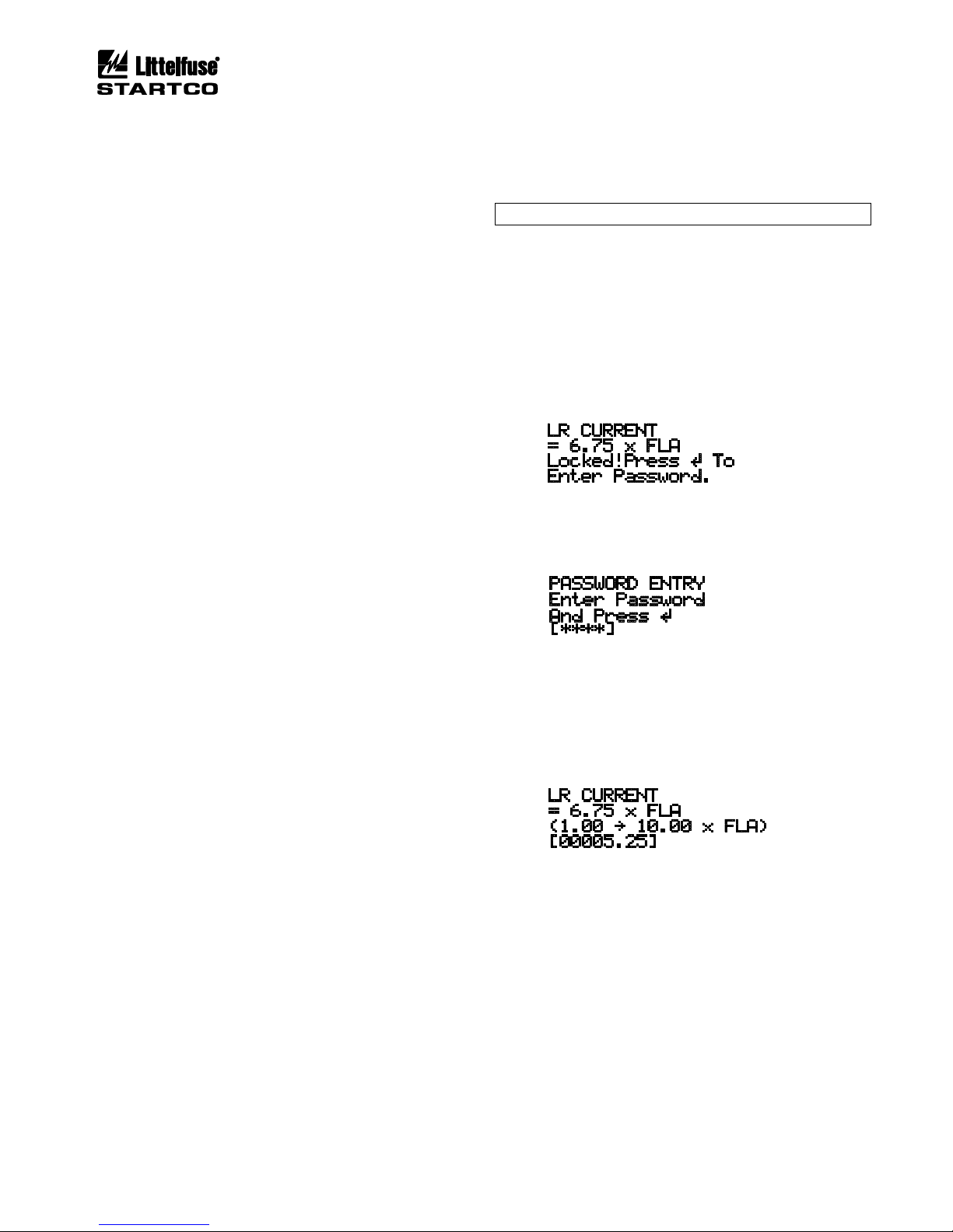
Page 4-9
MPS Motor Protection System Rev. 6-F-022117
Operation and Setup
4.3.5.3 DATA LOGGING
OPI Menu: Messages | Event Records
Trip-record data, start-record data, and Emergency
Thermal Resets (ETR) are logged. Trip-record data
includes the time of trip, cause of trip, and pre-trip
(1)
data. ETR records contain a snapshot of the data prior to
an ETR.
Trip or ETR records include:
• Time Stamp YY/MM/DD HH:MM:SS
• Vab, Vbc, Vca, Ia, Ib, Ic, and 3I0 at time of trip or ETR
• Unbalance (I2/I1, V2/V1) at time of trip or ETR
• P, Q, S, and PF at time of trip or ETR
(1)
• Used I2t at time of trip or ETR
• PTC/RTD temperature data if applicable
• Differential module data if applicable
Start records
(2)
are triggered by motor current and
include:
• Time Stamp YY/MM/DD HH:MM:SS
• Maximum values of Ia, Ib, Ic, and 3I0 during the start
• Maximum value of I2/I
1
(4)
, V2/V1 during the start
• Minimum values of Vab, Vbc, Vca during the start
• Maximum differential currents during the start if
applicable
• I2t used during the start
(3)
• Start duration
• PTC/RTD temperature data if applicable
Record Type .............................. Trip/Start/ETR
Number of Records .................... 64 (First In First Out)
(1)
Recorded values for power quantities (P, Q, S, PF)
are averages of measurements over the previous 16
cycles.
(2)
Values updated at 0.5-s intervals during a start.
Record logged when the Run mode is entered.
(3)
Starting I2t can be used to determine the I2t Lockout
Level. See Section 5.2.
(4)
Measurements enabled 0.5 s after start current is
detected.
4.3.5.4 STATISTICAL DATA
OPI Menu: Messages | Statistics
OPI Menu: Setup | System Config | Maintenance
The MPS records the following statistical data:
• Running hours.
• Counters for all trips.
Statistical data can be cleared in the Maintenance
menu.
4.3.5.5 EMERGENCY THERMAL RESET
OPI Menu: Messages | Emerg I2t Reset
The Emerg I
2
t Reset menu is used to reset the thermal
memory. See Section 5.2.3.
4.3.6 PASSWORD ENTRY AND PROGRAMMING
OPI Menu: Setup | System Config | Password Timeout
NOTE: Factory default password is 1111.
All set points are locked from changes until the fourcharacter password is entered. If set-point access is
locked, the user is prompted to enter the password. Once
entered, set-point access is allowed and remains enabled
until a key has not been pressed for the time defined by
the Password Timeout set point.
EXAMPLE:
Prior to password entry:
When ENTER is pressed, the Password Entry display
is shown:
Use the left- and right-arrow keys to select the position
of the flashing cursor. Use the up- and down-arrow keys
to select password characters. Press ENTER.
When the correct password is entered, a flashing
cursor is displayed, the set-point range and units are
shown, and set points can be changed.
Use the up- and down-arrow keys to change a setpoint update-field character, and use the left- and rightarrow keys to move between characters. Press ENTER
to update the set point, or press ESC to exit the display
without changing the set point. A set point is set to the
minimum or maximum value of its range if an out-ofrange value is entered. Press ESC to exit the set-pointupdate screen.
Page 46
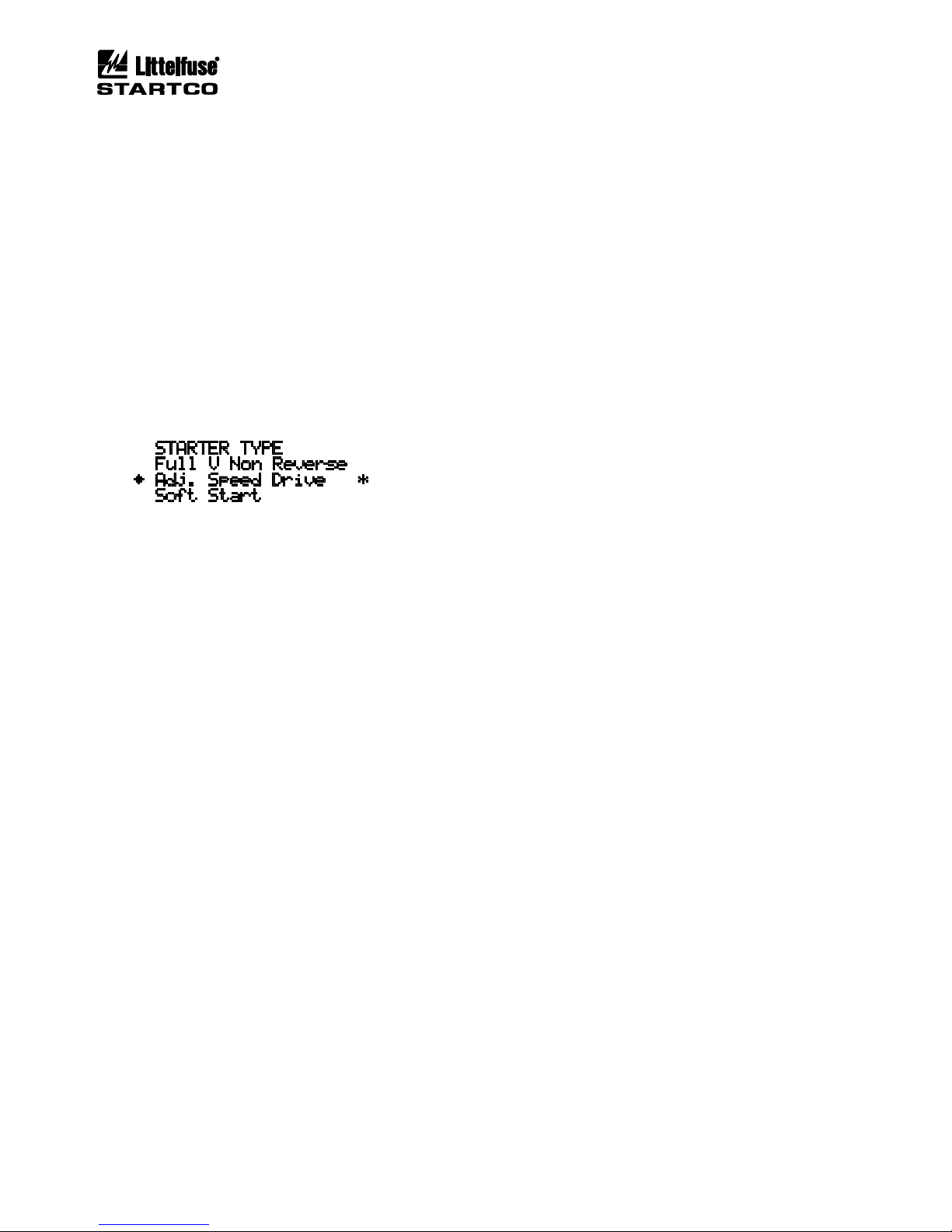
Page 4-10
MPS Motor Protection System Rev. 6-F-022117
Operation and Setup
The sequence for set-point characters depends upon
the set-point type. The character sequence for numeric
set points is:
. . . 0 1 2 3 4 5 6 7 8 9 . 0 1 2 3 . . . . .
The character sequence for string set points is:
. . . [0…9] [A…Z] [a…z] SP - . / [0…9] [A…Z] . . . . .
Characters forming a series are shown in brackets and
“SP” represents the space character.
For set points requiring selection from a list, the up
and down arrow keys are used to scroll through the
items. In the same manner as menu items, selections are
displayed using one of the three cursor symbols (½«²)
preceding the item. Pressing ENTER selects the item
and that item is indicated by the “∗” symbol to its right.
EXAMPLE:
4.4 MPS-RTD
OPI Menu: Setup | Hardware | RTD Modules
OPI Menu: Setup | Protection | RTD Temperature
The MPS-RTD module extends MPS protective
functions to include multiple-RTD temperature
monitoring. It has eight inputs that can be individually
configured for RTD type, trip and alarm settings, name,
and function. The RTD types are 10-Ω copper, 100-Ω
nickel, 120-Ω nickel, and 100-Ω platinum. Functions are
stator, bearing, load, and ambient.
Control voltage for the MPS-RTD (24 Vdc) is
supplied by the MPS-CTU and communication is
through an RS-485 link. This allows the MPS-RTD to
be mounted up to 1.2 km (4,000’) from the MPS-CTU.
To enable RTD protection, the total number of
modules must be selected in the Total Modules menu and
Temperature Trip Action or Alarm Action must be
enabled. If RTD protection is disabled, metering
information is still provided. Up to three modules can be
used. In the RTD Modules menu, the action to be taken
by the MPS-CTU in response to loss of communication
is selected.
When the hardware has been configured, temperature
set points and sensor-failure action selections in the RTD
Temperature menu are used for RTD temperature
protection. See Section 5.27.
4.5 MPS-DIF
OPI Menu: Setup | Hardware | DIF Module
OPI Menu: Setup | Protection | Differential
The MPS-DIF Differential Module extends MPS
protective functions to include phase-differential
monitoring. It has three differential-CT inputs that can
be used in a three-CT core-balance connection, a sixdifferential-CT connection, or a six-CT connection that
includes phase-CT MPS inputs. The core-balance, threeCT connection is recommended.
Control voltage for the MPS-DIF (24 Vdc) is supplied
by the MPS-CTU and communication is through an
RS-485 link. This allows the MPS-DIF to be mounted
up to 1.2 km (4,000’) from the MPS-CTU, and the link
can be shared by other MPS I/O modules.
Enable the module and loss-of-communications
protection in the Hardware | Dif Module menu, and
choose protection settings in the Protection | Differential
menu. See Section 5.25.
4.6 WAVEFORM CAPTURE
The MPS continuously samples seven channels of data
consisting of the three-phase currents, three-phase
voltages, and the earth leakage current. The sample rate
is fixed at 16 samples/cycle and sample data (Trace
Data) for each channel are stored in a 4800 sample
memory. This provides a record depth of 300 cycles, or
5 seconds of pre-trip data at 60 Hz.
When a trip occurs, Trace Data capture is halted and a
date and time stamp is added. Trace Data values are
retrieved using SE-Comm-RIS which generates an
industry-standard COMTRADE and CSV file. See
Appendix E for data mapping definitions and conversion
formulas.
The Setup | System Config | Trace Auto-Start menu is
used to set the Trace Data start mode after a trip has
occurred. When enabled, Trace Data capture
automatically starts when reset is pressed. When
disabled, Trace Data capture requires a manual re-start
using the Messages | Re-Start Trace. This allows the
MPS to be reset and the trip data to be analyzed at a later
time. Trace Data start can also be activated using
Command 13 via the communications interface.
Trace Data are stored in volatile memory and are lost if
the MPS loses supply voltage. Regardless of the Trace
Auto-Start setting, waveform capture starts automatically
on power-up if there are no previous trips.
Page 47
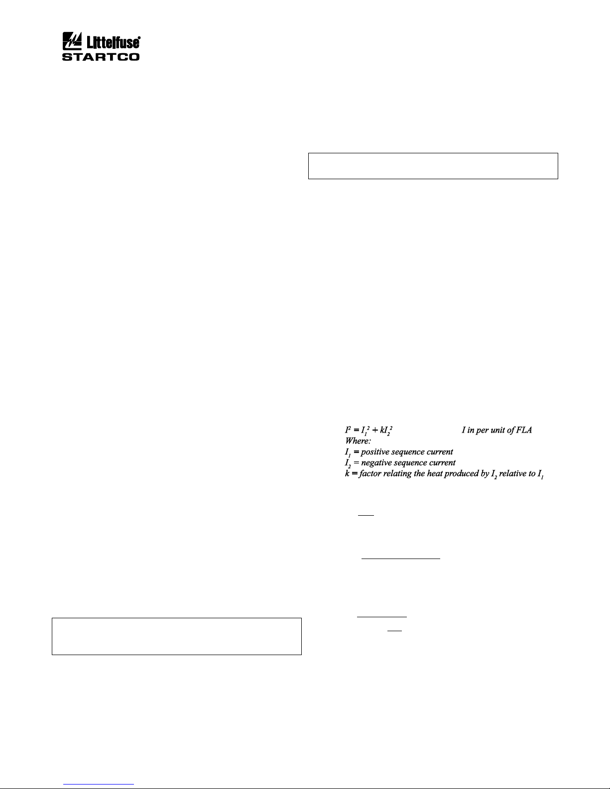
Page 5-1
MPS Motor Protection System Rev. 6-F-022117
Protective Functions
5. PROTECTIVE FUNCTIONS
5.1 GENERAL
The MPS measures true RMS, peak, and fundamentalfrequency values of current and voltage. Fundamentalfrequency values (magnitude and phase angle) are obtained
using Discrete-Fourier Transform (DFT) filtering that
rejects dc and harmonics. The type of measurement used
for a protective function is indicated in each section.
Unless otherwise indicated, protective functions have a
programmable definite-time characteristic. Each protective
function can be assigned a trip action that defines the
output contact(s) used. Except for overload protection,
which has auto-reset available, MPS trips are latched.
Trips are logged.
Trip-action selections are:
• Disable
• Trip1
(1)
• Trip2
(2)
• Trip3
(2)
• Trip1 and Trip2
• Trip1 and Trip3
• Trip1 and Trip2 and Trip3
• Trip2 and Trip3
(1)
Initiates a starter stop. See Section 6.
(2)
Does not initiate a starter stop. See Section 6.
Most protection functions can be assigned an alarm
action. Alarms auto-reset and are not logged.
Alarm-action selections are:
• Disable
• Alarm1
• Alarm2
• Alarm3
• Alarm1 and Alarm2
• Alarm1 and Alarm3
• Alarm1 and Alarm2 and Alarm3
• Alarm2 and Alarm3
To operate output contacts, trip and alarm actions must
be assigned to output relays using the Setup | Relay Outputs
menu. See Section 4.2.7.
NOTE: When starter functions are used, only set points
with a Trip Action that includes Trip1 will cause the starter
to stop when a trip occurs.
When enabled, Jam, Power-Factor, Undercurrent, and
Underpower protection are not active during a start and are
active in the Run mode. The Run mode is initiated when
motor current is between 1.5 x (CT-Primary Rating/FLA)
and 125% FLA for the duration of the setting in the Setup ⏐
System Ratings ⏐ Run Mode Delay menu.
Run Mode Delay is adjustable from five to 120 seconds.
Run-mode status is displayed in the Metering | System State
menu. One of three states are indicated: Motor:Start,
Motor:Run, or Motor:Off. The motor status line also
indicates one of two states for the Reduced Overcurrent
(ROC) feature: ROC:OFF or ROC:ON. See Section 5.5.
NOTE: See Appendix B for default set-point values.
Per-unit notation (pu) is used. 1 pu = 100%.
5.2 OVERLOAD
At a minimum, for customized thermal-overload
protection, motor data, must be entered for Full-Load
Current, Service Factor, Locked-Rotor Current, Cold
Locked-Rotor Time, and Hot Locked-Rotor Time.
5.2.1 THERMAL MODEL
OPI Menu: Setup | Protection | Overload
OPI Menu: Setup | System Ratings
A NEMA- or K-factor-based thermal-model algorithm
can be selected.
The NEMA-based algorithm uses the square of the
maximum RMS phase current as the thermal-model input:
2
2
rmsmax
II =
I in per unit of FLA
The K-factor-based algorithm uses a thermal-model
input based on true positive- and negative-sequence
component values:
A conservative value for k is:
k =
230
I
L
2
Where:
IL=
locked rotor current
full load current
The thermal time constant (τ) used by the thermal model
to provide starting and running I2t protection is:
unitperinfactorservicesf
ondssecintimerotorlockedcoldT
:Where
I
sf
ln
T
C
2
L
2
C
=
=
⎟
⎟
⎠
⎞
⎜
⎜
⎝
⎛
−−=τ1
When the motor is stopped, the thermal model uses a
time constant that is user selectable as a multiple (Cooling
Factor) of the thermal time constant (τ).
Page 48

Page 5-2
MPS Motor Protection System Rev. 6-F-022117
Protective Functions
The cold-curve time-to-trip (t) for current above
FLA × sf is:
τ×
⎟
⎟
⎠
⎞
⎜
⎜
⎝
⎛
−−=
2
2
1
I
sf
lnt
The MPS provides indication of thermal trend and used
thermal capacity. Thermal trend is the value that used
thermal capacity is tending toward and it is a function of
the square of motor current. For currents greater than or
equal to FLA × sf, time-to-trip is displayed in Metering |
Thermal Capacity. The thermal trend value (Trend I2t) is:
%100
2
2
2
×
⎟
⎟
⎠
⎞
⎜
⎜
⎝
⎛
=
sf
I
tITrend
For currents less than FLA × sf, the thermal trend value
is:
ondssecintimerotorlockedhotT
Where
T
TT
sf
I
tITrend
H
C
HC
=
×
⎟
⎟
⎠
⎞
⎜
⎜
⎝
⎛
−
×
⎟
⎟
⎠
⎞
⎜
⎜
⎝
⎛
=
:
%10 0
2
2
2
The curve shown in Fig. 5.1 is a Class-20 thermalprotection curve (20-s trip @ 600% FLA) with a service
factor of 1.15. FLA multiplied by service factor is the
current at which used thermal capacity begins to trend
towards a trip. Time-to-trip approaches infinity when
I = FLA × sf. Service factor has little influence on time-totrip when motor current is greater than 300% FLA.
MPS thermal-overload protection is dynamic. Time to
trip at any overload current depends on the value of Used
I2t ⎯ as Used I2t increases, time to trip decreases. This is
illustrated in Fig. 5.1 by the protection curves labelled 25%
Used I2t, 50% Used I2t, and 75% Used I2t. Programming
software SE-Comm-RIS has a plot function to display and
export MPS protection curves.
An overload alarm occurs when Used I2t reaches the I2t
Alarm Level set point.
An overload trip occurs when Used I2t reaches 100%.
When an overload trip occurs, reset is not allowed until
Used I2t falls below the I2t Inhibit Level set point. The
time-to-reset in minutes is:
t = -
τ
× Cooling Factor × ln(I2t Inhibit Level) / 60
Time-to-reset is displayed in the Metering ⏐ Thermal
Capacity menu. The thermal model has three reset modes;
Normal, Auto, and Multiple Motor Seq. The thermaloverload reset mode is set using the Setup ⏐ Protection ⏐
Overload ⏐ I2t Reset Type menu.
In the Normal mode, a thermal-overload trip reset is not
allowed until Used I2t falls below the I2t Inhibit Level
setting. A reset input is required to reset the trip. Normal
is the default reset mode.
In the Auto mode, a thermal-overload trip is
automatically reset when Used I2t falls below the I2t Inhibit
Level setting.
NOTE: If the starter circuit is configured for 2-wire control,
the motor can start without warning when Auto mode is
selected. A warning label may be required.
In the Multiple Motor Seq. mode, Used I2t decreases
exponentially with a fixed two-second time constant when
there is no motor current. This mode is used in
applications where one overload relay is used to protect
several motors operating in sequence with only one motor
running at any one time. A two-second stop is required
between starts so that Used I2t decreases sufficiently to
allow the next motor to start. It is assumed that each motor
is allowed to cool between starts. Motor life may be
decreased if this feature is used in single-motor
applications. When an overload trip occurs, the trip is
latched but can be reset two seconds after the trip.
When I2t Start Inhibit is enabled, the I2t Inhibit Level set
point can be used to prevent a start with insufficient I2t
available. When Used I2t is above the I2t Inhibit Level set
point and motor current is not detected, Alarm1 is issued,
starter functions Start1 and Start2 are disabled, and the
relay assigned to Start Inhibit is energized. The time until
a start is permitted is displayed in Metering | Thermal
Capacity, and I2t Inhibit Alarm is displayed in the Trip and
Alarm message window. When Used I2t falls below the I2t
Inhibit Level set point, the relay assigned to Start Inhibit is
de-energized, the inhibit alarm is cancelled, and starter
functions Start1 and Start2 are enabled. Trips require a
manual reset. I2t Start Inhibit is removed when current is
detected. This applies in both Starter and Protection-only
modes. The Start-Inhibit relay is shared with the Starts-PerHour function. See Section 5.23.
If the motor is equipped with RTD sensors, the thermal
model can compensate for high ambient temperature and
loss of ventilation. See Section 5.27.
I2t used during each start is recorded in Messages ⏐
Event Records. This information can be used to determine
the I2t Inhibit Level set point to ensure sufficient I2t is
available to complete a start, and to minimize thermaloverload-reset time.
FLA Rating ........................... 1.00 to 5,000.00 A
Service Factor ....................... 1.00 to 1.25
Locked-Rotor Current ........... 1.50 to 10.00 x FLA
Hot Locked-Rotor Time ....... 0.10 to 100.00 s
Cold Locked-Rotor Time ...... 0.10 to 100.00 s
Cooling Factor ...................... 0.10 to 10.00
Model Type: ......................... NEMA, K-Factor
I2t Reset Type ........................ Normal, Auto,
Multiple Motor Sequence
K-Factor ................................ 1.00 to 10.00
I2t Alarm ............................... 0.50 to 1.00 pu
I2t Inhibit Level 0.10
to 0.90 pu
Page 49
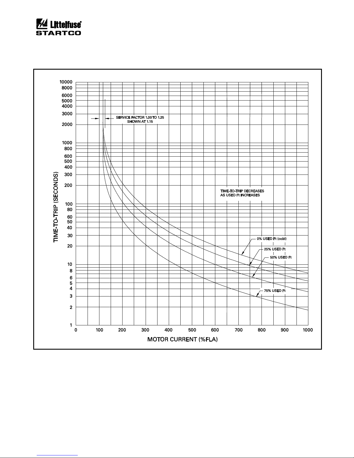
Page 5-3
MPS Motor Protection System Rev. 6-F-022117
Protective Functions
I2t Start Inhibit ...................... Enable/Disable
Protection .............................. Enable/Disable Trip1, 2, 3
Enable/Disable Alarm1, 2, 3
Measurement Method ........... DFT or RMS
FIGURE 5.1 Class-20 Overload Curve.
Page 50

Page 5-4
MPS Motor Protection System Rev. 6-F-022117
Protective Functions
5.2.2 LOCKED-ROTOR TIMES
In all cases, values for TH and TC should be obtained
from the motor manufacturer. The following information
is provided to assist in selecting values for TH and TC only
if manufacturer data is not available.
Heater-style overload elements are available as
Class 10, Class 20, or Class 30. Class 20 is recommended
for general applications, Class 10 is used for motors with
short locked-rotor time capability, and Class 30 is used in
high-inertia applications to allow additional accelerating
time where motors are within Class-30 performance
requirements. These overloads can be replicated by
setting TC = 10, 20, or 30 s; TH = 0.1 s; and Locked-Rotor
Current = 6.00 x FLA.
An induction motor built to the NEMA MG 1 standard
is capable of:
• two starts in succession (coasting to rest between
starts) with the motor initially at ambient temperature
(cold start)
• one start with the motor initially at a temperature not
exceeding its rated-load operating temperature (hot
start).
Since the connected load has a direct influence on
motor heating during a start, NEMA MG 1 defines the
load torque and the load inertia (Wk2) for these starts as a
function of the motor’s rated power and synchronous
speed. To satisfy the cold-start requirement, a start must
not use more than 50% thermal capacity. To satisfy the
hot-start requirement, used thermal capacity at steady
state must be less than 50%.
If the thermal model in the MPS has the correct value
of TC and if Used I2t increases by 50% during a start, the
load is equal to the NEMA-defined load and two starts
from cold will be permitted. If Used I2t increases by more
than 50% during a start, the load is greater than the
NEMA-defined load and two starts from cold should not
be permitted — a delay is required between starts. The
appropriate delay can be obtained by enabling I2t Start
Inhibit and setting the I2t Inhibit Level equal to 100%
minus the I2t used during a start (a slightly lower level is
recommended to allow for supply and load variations). If
Used I2t increases by less than 50% during a start, the
load is less than the NEMA-defined load and two starts
from cold will be permitted.
The magnitude of TH relative to TC determines if a hot
start will be permitted if I2t Start Inhibit is enabled and the
I2t Inhibit Level is set as described above. If Used I2t
increases by 50% or less during a start, a hot start will be
permitted if TH is equal to or greater than 50% of TC.
Increasing TH above 50% of TC is not recommended
unless specific information is available with respect to TH.
5.2.3 EMERGENCY THERMAL RESET
OPI Menu: Messages | Emerg I2t Reset | Reset I2t Memory
Emergency Thermal Reset (ETR) sets Used I2t to 0%,
resets starts-per-hour variables, and disables PTC and
RTD temperature trips. Program access (password) is
required. Disabled-temperature protection is indicated by
t° Disabled by ETR in the Status Messages display. If
PTC or RTD temperature protection is not enabled, t°
Disabled by ETR will not be displayed. Stator RTD or
PTC trips are reset when ETR is performed regardless of
measured temperatures. Temperature protection must be
re-enabled in the Messages | Emerg I2t Reset | Reenable
Temp menu, or by cycling supply voltage.
Temperature alarms and sensor verification remain
enabled during ETR.
NOTE: Temperature protection is not automatically reenabled after an Emergency Thermal Reset.
5.3 OVERCURRENT
OPI Menu: Setup | Protection | Overcurrent
Overcurrent protection is based on the largest
fundamental-frequency component (DFT) of the three
phase currents. An alarm-level setting is not provided.
When enabled, overcurrent protection is active at all
times. It is not bypassed during a start.
Trip Level ............................. 1.00 to 15.00 x CT-Primary
Rating (Ip)
Trip Delay (TD) .................... 0.00 to 10.00 s
(See Tables 5.1 and 5.2)
Protection .............................. Enable/Disable Trip1, 2, 3
Measurement Method ........... DFT
TABLE 5.1 TRIP TIME
FAULT LEVEL
(multiples of trip-
level setting)
(1)
TRIP RELAYS
(ms)
(± 10 ms)
STARTER
RELAYS (ms)
(± 15 ms)
2
5
10
18
TD + 35
TD + 30
TD + 27
TD + 26
TD + 45
TD + 40
TD + 37
TD + 36
(1)
For overcurrent faults less than 18 x Ip.
For earth faults less than 1 x Ie.
TABLE 5.2 FAULT DURATION REQUIRED FOR TRIP
FAULT LEVEL
(multiples of trip-
FAULT DURATION
(ms)
level setting)
(1)
TD ≤ 20 ms
TD > 20 ms
2
5
10
18
10
5
2
1
TD – 10
TD – 15
TD – 18
TD – 19
(1)
For overcurrent faults less than 18 x Ip.
For earth faults less than 1 x Ie.
Page 51
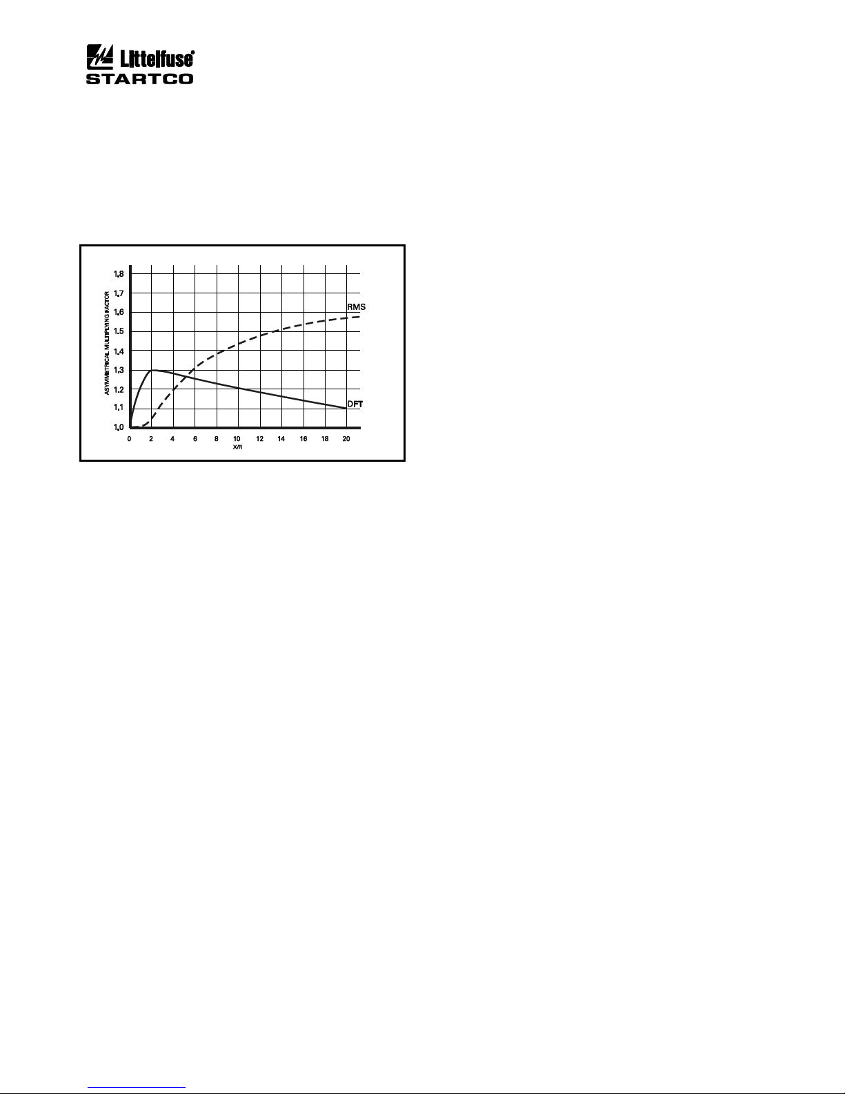
Page 5-5
MPS Motor Protection System Rev. 6-F-022117
Protective Functions
The asymmetrical-current multipliers for RMS and
DFT measuring methods are shown in Fig. 5.2. X/R is
the ratio of system reactance to system resistance.
Typical X/R values are 6.6 for a low-voltage system, 15
for a medium-voltage system, and can be as high as 25 for
a high-voltage system. As shown by the graph, the DFT
filters the dc component so that the overcurrent setting
can be set closer to the symmetrical fault value.
FIGURE 5.2 Asymmetrical-Current Multipliers.
5.4 AUXILIARY OVERCURRENT
OPI Menu: Setup | Protection | Aux Overcurrent
Auxiliary overcurrent is the same as overcurrent
protection. This function is intended to be used when
backup protection for the overcurrent function is required.
Trip Level ............................. 1.00 to 15.00 x CT-Primary
Rating (Ip)
Trip Delay ............................. 0.00 to 10.00 s
(See Tables 5.1 and 5.2)
Protection .............................. Enable/Disable Trip1, 2, 3
Measurement Method ........... DFT
5.5 REDUCED OVERCURRENT
OPI Menu: Setup | Protection | Reduced OC
Reduced overcurrent is used to reduce the overcurrent
set point when performing maintenance while a motor is
running. This mode of operation can be used to meet
NEC 240.87 Arc Energy Reduction (B) (3) Energyreducing maintenance switching with local status
indicator.
Reduced overcurrent is controlled by a digital input
assigned to Reduced OC. When the digital input is not
applied, this set point is operational and when the digital
input is applied, this set point is not operational. When
reduced overcurrent is selected, ROC:ON is displayed in
the Metering | System State menu and a relay assigned to
Reduced OC will be energized.
The Protection selection must include Trip1, Trip2, or
Trip3. If Disable is selected, Reduced OC mode is
disabled.
Trip Level ............................. 1.00 to 15.00 x CT-Primary
Rating (Ip)
Trip Delay ............................. Fixed at 0.00 (Instantaneous)
See Tables 5.1 and 5.2
Protection .............................. Enable/Disable Trip1, 2, 3
Measurement Method ........... DFT
5.6 JAM
OPI Menu: Setup | Protection | Jam
A trip or alarm occurs if a jam condition is detected.
Jam protection is active when the motor is in the Run
mode, allowing protection to be set below motor-starting
current.
Trip Level ............................. 1.00 to 10.00 x FLA
Trip Delay ............................. 1.00 to 100.00 s
Alarm Level .......................... 1.00 to 10.00 x FLA
Alarm Delay ......................... 1.00 to 100.00 s
Protection .............................. Enable/Disable Trip1, 2, 3
Enable/Disable Alarm1, 2, 3
Measurement Method ........... DFT
5.7 EARTH FAULT
OPI Menu: Setup | Protection | Earth Fault
Earth-fault protection is based on the fundamentalfrequency component of zero-sequence current.
Trip Level ............................. 0.05 to 1.00 x EF-CT-
Primary Rating (Ie)
Trip Delay ............................. 0.00 to 100.00 s
(See Tables 5.1 and 5.2)
Alarm Level .......................... 0.05 to 1.00 x Ie
Alarm Delay ......................... 0.00 to 100.00 s
Protection ............................. Enable/Disable Trip1, 2, 3
Enable/Disable Alarm1, 2, 3
Measurement Method ........... DFT
5.8 CURRENT UNBALANCE
OPI Menu: Setup | Protection | Unbalance (I)
OPI Menu: Setup | System Config | Ip Threshold
Positive-sequence current (I1) and negative-sequence
current (I2) are used to determine current unbalance (I2/I1).
The unbalance display range is 0.00 to 1.00 where 1.00 is
100% unbalance—a single-phase condition. Negative
unbalance will be indicated if current inputs are connected
B-A-C. Severe unbalance may be indicated if phase-CT
polarity is incorrect.
Lightly loaded systems, especially with synchronous
motors, may cause false current unbalance trips. The IP
Threshold sets the current level where unbalance
protection becomes active. The IP Threshold is based on
the maximum of the three-phase currents.
For example, if the CT-primary rating (Ip) is 100 A, and
Ip Threshold is set to 0.25, current unbalance protection
will be active above 25 A.
Page 52

Page 5-6
MPS Motor Protection System Rev. 6-F-022117
Protective Functions
Trip Level ............................. 0.05 to 1.00
Trip Delay ............................. 1.00 to 100.00 s
Alarm Level .......................... 0.05 to 1.00
Alarm Delay ......................... 1.00 to 100.00 s
Protection .............................. Enable/Disable Trip1, 2, 3
Enable/Disable Alarm1, 2, 3
IP Threshold .......................... 0.10 to 0.50 x CT-primary
rating (IP)
Measurement Method ........... DFT
5.9 PHASE LOSS—CURRENT
OPI Menu: Setup | Protection | Phase Loss (I)
Phase loss is a severe form of unbalance. When phase
loss occurs, negative-sequence current (I2) is equal to
positive-sequence current (I1) and current unbalance is
100% or 1.00 pu. The phase-loss algorithm considers I2/I1
from 0.90 to 1.00 to be a phase loss. This occurs when
one phase is open resulting in two current vectors at 180°.
Set the phase-loss-trip delay lower than the unbalance trip
delay to avoid an unbalance trip in the event of a phase
loss.
NOTE: An open CT will result in I2/I1=0.5 because the
phase angle between the other two phases remain at 120°.
This is not considered a phase loss.
Trip Delay ............................. 1.00 to 100.00 s
Protection .............................. Enable/Disable Trip1, 2, 3
Measurement Method ........... DFT
5.10 PHASE REVERSE—CURRENT
OPI Menu: Setup | Protection | Phase Rev (I)
If the current phase sequence is B-A-C, the magnitude
of negative-sequence current will be larger than the
magnitude of positive-sequence current.
Trip and Alarm Delay
(1)
....... 1.00 to 100.00 s
Protection .............................. Enable/Disable Trip1, 2, 3
Enable/Disable Alarm1, 2, 3
Measurement Method ........... DFT
(1)
Single set point applies to Trip and Alarm.
5.11 UNDERCURRENT
OPI Menu: Setup | Protection | Undercurrent
Undercurrent protection is loss-of-load protection and
is active when the motor is in the Run mode. A trip or
alarm is initiated if current remains below the set point for
the programmed delay.
Trip Level ............................. 0.10 to 1.00 x FLA
Trip Delay ............................. 1.00 to 100.00 s
Alarm Level .......................... 0.10 to 1.00 x FLA
Alarm Delay ......................... 1.00 to 100.00 s
Protection .............................. Enable/Disable Trip1, 2, 3
Enable/Disable Alarm1, 2, 3
Measurement Method ........... DFT
5.12 OVERVOLTAGE
OPI Menu: Setup | Protection | Overvoltage
A trip or alarm occurs if the maximum line-to-line
voltage exceeds the set point.
Trip Level ............................. 1.00 to 1.40 x System
Voltage Rating (Vp)
Trip Delay ............................. 1.00 to 500.00 s
Alarm Level .......................... 1.00 to 1.40 x Vp
Alarm Delay ......................... 1.00 to 500.00 s
Protection .............................. Enable/Disable Trip1, 2, 3
Enable/Disable Alarm1, 2, 3
Measurement Method ........... DFT
5.13 VOLTAGE UNBALANCE
OPI Menu: Setup | Protection | Unbalance (V)
Positive-sequence voltage (V1) and negative-sequence
voltage (V2) are used to determine voltage unbalance
(V2/V1). The unbalance display range is 0.00 to 1.00
where 1.00 is 100% unbalance—a single-phase condition.
A negative unbalance will be indicated if voltage inputs
are connected B-A-C.
Trip Level ............................. 0.05 to 1.00
Trip Delay ............................. 1.00 to 100.00 s
Alarm Level .......................... 0.05 to 1.00
Alarm Delay ......................... 1.00 to 100.00 s
Protection .............................. Enable/Disable Trip1, 2, 3
Enable/Disable Alarm1, 2, 3
Measurement Method ........... DFT
5.14 PHASE LOSS—VOLTAGE
OPI Menu: Setup | Protection | Phase Loss (V)
Phase loss is a severe form of unbalance. When phase
loss occurs, negative-sequence voltage (V2) is equal to
positive-sequence voltage (V1) and voltage unbalance is
100% or 1.00 pu. The phase-loss algorithm considers
V2/V1 from 0.90 to 1.00 to be a phase loss. Set the phaseloss trip delay lower than the unbalance trip delay to
avoid an unbalance trip in the event of a phase loss.
Trip Delay ............................. 1.00 to 100.00 s
Protection .............................. Enable/Disable Trip1, 2, 3
Measurement Method ........... DFT
5.15 PHASE REVERSE—VOLTAGE
OPI Menu: Setup | Protection | Phase Rev (V)
If the voltage phase sequence is B-A-C, the magnitude
of the negative-sequence voltage will be larger than the
magnitude of the positive-sequence voltage.
Trip and Alarm Delay
(1)
....... 1.00 to 100.00 s
Protection .............................. Enable/Disable Trip1, 2, 3
Enable/Disable Alarm1, 2, 3
Measurement Method ........... DFT
(1)
Single set point applies to Trip and Alarm.
Page 53

Page 5-7
MPS Motor Protection System Rev. 6-F-022117
Protective Functions
5.16 UNDERVOLTAGE
OPI Menu: Setup | Protection | Undervoltage
A trip or alarm occurs if the minimum line-to-line
voltage is less than the set point.
Trip Level ............................. 0.50 to 1.00 x System
Voltage Rating (Vp)
Trip Delay ............................. 1.00 to 500.00 s
Alarm Level .......................... 0.50 to 1.00 x Vp
Alarm Delay ......................... 1.00 to 500.00 s
Protection .............................. Enable/Disable Trip1, 2, 3
Enable/Disable Alarm1, 2, 3
Measurement Method ........... DFT
5.17 UNDERPOWER
OPI Menu: Setup | Protection | Underpower
Apparent power (S) is defined by S = P + jQ. A trip or
alarm is initiated when the real power (P) magnitude
remains below the set point for the programmed delay.
Protection is enabled when the motor is in the Run mode.
See Section 7.2.
The Underpower setting is in per unit of rated power
where 1.00 pu is defined as the System Voltage x FLA
Rating x √3. The absolute value of power is used.
Trip Level ............................. 0.10 to 1.00
Trip Delay ............................. 0.50 to 500.00 s
Alarm Level .......................... 0.10 to 1.00
Alarm Delay ......................... 0.50 to 500.00 s
Protection .............................. Enable/Disable Trip1, 2, 3
Enable/Disable Alarm1, 2, 3
5.18 REVERSEPOWER
OPI Menu: Setup | Protection | Reversepower
Apparent power (S) is defined by S = P + jQ. A trip or
alarm is initiated when the real reverse power (P)
magnitude (negative power) is higher than the set point
for the programmed delay. See Section 7.2.
The Reversepower setting is in per unit of rated power
where 1.00 pu is defined as the System Voltage x FLA
Rating x √3. The magnitude of the negative power is
used and protection is only active when negative power is
detected.
Trip Level ............................. 0.10 to 1.00
Trip Delay ............................. 0.50 to 500.00 s
Alarm Level .......................... 0.10 to 1.00
Alarm Delay ......................... 0.50 to 500.00 s
Protection .............................. Enable/Disable Trip1, 2, 3
Enable/Disable Alarm1, 2, 3
5.19 POWER FACTOR—QUADRANT 4
OPI Menu: Setup | Protection | PF Quandrant4
OPI Menu: Setup | System Config | Ip Threshold
A trip or alarm occurs if the absolute value of power
factor in quadrant 4 is less than the set point. In quadrant
4, both Watts and Vars are positive (Importing).
Power-factor protection is active when the motor is in
the Run mode. Run mode is defined in Section 5.1.
The Ip Threshold sets the point where power-factor
protection becomes active.
Trip Level ............................. 0.50 to 1.00
Trip Delay ............................. 0.20 to 500.00 s
Alarm Level .......................... 0.50 to 1.00
Alarm Delay ......................... 0.20 to 500.00 s
IP Threshold .......................... 0.10 to 0.50 x CT-primary
rating (IP)
Protection .............................. Enable/Disable Trip1, 2, 3
Enable/Disable Alarm1, 2, 3
5.20 POWER FACTOR—QUADRANT 3
OPI Menu: Setup | Protection | PF Quandrant3
OPI Menu: Setup | System Config | Ip Threshold
A trip or alarm occurs if the absolute value of power
factor in quadrant 3 is less than the set point. In quadrant
3, Watts are negative (Exporting) and Vars are positive
(Importing).
Power-factor protection is active when the motor is in
the Run mode. Run mode is defined in Section 5.1.
The Ip Threshold sets the point where power-factor
protection becomes active.
Trip Level ............................. 0.50 to 1.00
Trip Delay ............................. 0.20 to 500.00 s
Alarm Level .......................... 0.50 to 1.00
Alarm Delay ......................... 0.20 to 500.00 s
IP Threshold .......................... 0.10 to 0.50 x CT-primary
rating (IP)
Protection .............................. Enable/Disable Trip1, 2, 3
Enable/Disable Alarm1, 2, 3
5.21 UNDERFREQUENCY
OPI Menu: Setup | Protection | Underfrequency
A trip or alarm occurs when the frequency of the input
voltage (VA) is below the set point.
Underfrequency protection is inhibited when the input
voltage is less than 50% of rated input (Vp).
Trip Level ............................. 30.00 to 80.00 Hz
Trip Delay ............................. 0.50 to 500.00 s
Alarm Level .......................... 30.00 to 80.00 Hz
Alarm Delay ......................... 0.5 to 500.00 s
Protection .............................. Enable/Disable Trip1, 2, 3
Enable/Disable Alarm1, 2, 3
Page 54

Page 5-8
MPS Motor Protection System Rev. 6-F-022117
Protective Functions
5.22 OVERFREQUENCY
OPI Menu: Setup | Protection | Overfrequency
A trip or alarm occurs when the frequency of the input
voltage (VA) is above the set point.
Overfrequency protection is inhibited when the input
voltage is less than 50% of rated input (Vp).
Trip Level ............................. 30.00 to 80.00 Hz
Trip Delay ............................. 0.50 to 500.00 s
Alarm Level .......................... 30.00 to 80.00 Hz
Alarm Delay ......................... 0.50 to 500.00 s
Protection .............................. Enable/Disable Trip1, 2, 3
Enable/Disable Alarm1, 2, 3
5.23 STARTS PER HOUR / TIME BETWEEN STARTS
OPI Menu: Setup | Protection | Starts Per Hour
Starts-Per-Hour and Time-Between-Starts are useful
limits in a protective relay that incorrectly responds to
current below FLA. If the relay’s thermal model
accurately tracks a motor’s used thermal capacity under
all conditions, Starts-Per-Hour and Time-Between-Starts
are features that provide no additional protection. The
MPS does not require these features to provide protection,
but they are included to satisfy protection strategies
designed for protective relays without dynamic thermal
modeling.
The Starts-Per-Hour feature ensures that the
programmed number of starts per hour is not exceeded
and the Time-Between-Starts feature ensures that the
programmed time has elapsed between starts. The
available number of starts and time between starts is also
a function of the thermal model’s Used I2t value.
Consequently, the allowed number of starts may be less
than the starts-per-hour value and the time between starts
may be longer than the set-point value.
The number of starts and time between starts is
checked when the motor is stopped. A Starts/Hour Trip
or Starts/Hour Alarm is issued if a start will exceed the
# Starts Per Hour setting or if the time since the previous
start is less than the Time Between setting.
When a Starts/Hour Trip or Starts/Hour Alarm is
issued, the output relay assigned to Start Inhibit is
energized. The Start Inhibit relay is non-latching and can
be used as a start permissive. A Starts/Hour Trip will
remain latched until a reset is issued. The Start Inhibit
relay is shared with the thermal model’s I2t Inhibit
feature.
If motor current is detected regardless of the alarm or
trip condition, the Starts/Hour Alarm is removed, and
Starts/Hour Trip can be reset. The starts-per-hour
algorithm remains active but any trips or alarms are
suppressed until the motor is stopped.
The status of Starts-Per-Hour and Time-Between-Starts
is displayed in the Metering | Thermal Capacity menu. If
there are no trips or alarms, the number of available starts
(Sph Available) is displayed and if a trip or alarm is
present, the inhibit time (Sph Inhibit) is displayed. Since
the Metering | Thermal Capacity menu is also used to
display the thermal model status, messages are prioritized
as follows:
• I2t Reset Time
(1)
• I2t Trip Time
(1)
• I2t Inhibit Time
(1)
• Starts Per Hour Inhibit Time
(3)
• Starts Available
(2) (3)
An Emergency Thermal Reset (ETR) can be used to
initialize all thermal and starts-per-hour variables and to
reset a starts-per-hour trip. See Section 5.2.3.
Time Between Starts ......... 0.00 to 500.00 Minutes
Starts Per Hour
(2)
............... 1 to 10
Protection .......................... Enable/Disable Trip 1, 2, 3
Enable/Disable Alarm 1, 2, 3
(1)
Calculated from thermal model data.
(2)
The display range for the number of available starts is
-9 to +10.
(3)
Initialized when supply voltage is cycled.
5.24 FAILURE TO ACCELERATE AND UNDERSPEED
OPI Menu: Setup | Protection | Underspeed
OPI Menu: Setup | 4-20 Analog In | Input Function
OPI Menu: Setup | Digital Inputs | Tachometer
Failure-to-accelerate and underspeed protection are
available if the MPS has a tachometer signal. The
tachometer signal can originate from the High Speed
Input (HSI) or the analog input. If the analog input is set
to Motor Speed, it is used as the input to the algorithm,
otherwise the digital tachometer (HSI) is used. The
failure-to-accelerate algorithm is activated whenever a
start is detected. Start detection is based on motor
current. Set points 1 to 3 (for both speed and time) are
sequentially checked to confirm acceleration.
Motor at Full Speed (refer to Type T28, Bit 2 in
Appendix F) will be set when the measured tachometer
speed exceeds the Speed 3 threshold setting and the
Underspeed protection feature is enabled. If the Speed 3
threshold is not reached within Time 3, the MPS will trip
on failure-to-accelerate.
While running, the tachometer signal is continuously
measured and a trip occurs if the speed falls below the
Speed 3 setting.
Time 1 must be set less than or equal to Time 2 and
Time 2 must be set less than or equal to Time 3.
To enable display of the speed in the Metering | System
State menu, select Enable in the Setup ⏐ Digital Input ⏐
Tachometer ⏐ Enable/Disable menu, when the HSI input
is used.
Speed 1 ................................. 1.00 to 100% Sync Speed
Time 1 ................................... 1.00 to 1000.00 s
Speed 2 ................................. 1.00 to 100% Sync Speed
Time 2 ................................... 1.00 to 1000.00 s
Speed 3 ................................. 1.00 to 100% Sync Speed
Time 3 ................................... 1.00 to 1000.00 s
Protection .............................. Enable/Disable Trip1, 2, 3
Page 55

Page 5-9
MPS Motor Protection System Rev. 6-F-022117
Protective Functions
5.25 DIFFERENTIAL CURRENT PROTECTION
OPI Menu: Setup | Protection | Differential
OPI Menu: Setup | Hardware | DIF Module
OPI Menu: Setup | System Ratings | DF-CT Primary
The MPS-DIF provides three-phase differential
protection. It is intended to be used specifically for motor
protection and not intended for feeder or transformer
differential protection.
Enable the module and communications-loss protection
using the Setup ⏐ Hardware ⏐ DIF Module menu. The
module uses I/O module communications and both trip
and alarm actions are available in the event of
communications loss.
Set DF-CT Primary equal to the differential-CT-primary
rating. For the MPS summation connection, PH-CT
Primary and DF-CT Primary must be equal.
Trip and alarm settings are based on multiples of the
DF-CT Primary rating (Id).
Trip Level ............................. 0.10 to 15.00 x I
d
Trip Delay ............................. 0.00 to 10.00 s
Alarm Level .......................... 0.10 to 15.00 x Id
Alarm Delay ......................... 0.00 to 10.00 s
Protection .............................. Enable/Disable Trip1,2,3
Enable/Disable Alarm1,2,3
Measurement Method ........... DFT c/w CT saturation
compensation.
5.26 PTC TEMPERATURE
OPI Menu: Setup | Protection | PTC Temperature
A positive-temperature-coefficient (PTC) thermistor
input is provided on the MPS-CTU. The total resistance
of series-connected PTC thermistors must be less than
1,500 Ω at 20°C (68°F). A trip or alarm will occur when
series resistance exceeds 2,900 Ω.
NOTE: During Emergency Thermal Reset, a PTC trip is
reset and PTC-temperature protection is disabled. See
Section 5.2.3.
Protection .............................. Enable/Disable Trip1, 2, 3
Enable/Disable Alarm1, 2, 3
5.27 RTD TEMPERATURE
OPI Menu: Setup | Protection | RTD Temperature
OPI Menu: Setup | Hardware | RTD Module
Up to three RTD modules can be connected to the
MPS-CTU. Select the number of modules in the Setup |
Hardware | RTD Modules menu. Each module can
monitor eight RTD’s for a total of twenty-four RTD’s.
RTD type, function, and trip and alarm set points are
programmable for each RTD.
When an RTD type is selected, trip and alarm functions
are determined by Temperature Trip and Alarm settings.
During Emergency Thermal Reset, an RTD trip is reset
and RTD-temperature protection is disabled. See
Section 5.2.3.
RTD failure detection is provided. The actions for an
RTD failure are selectable as Trip1, 2, or 3 and as
Alarm1, 2, or 3. The selections apply to all RTD's.
The MPS supports three MPS-RTD modules with each
module supporting eight RTDs. Each RTD can be
assigned to one of eight function groups; Stator, Bearing,
Load, Ambient, Stator Voting, Bearing Voting, Load
Voting, and Ambient Voting. The specific assignment is
set using the Setup | Protection | RTD Temperature |
Module x | Function menu. Regardless of the assigned
function, individual RTD trip and alarm setpoints remain
active.
When an RTD is assigned to a voting group, it
participates in the voting logic. Within a voting group,
two RTDs must indicate a temperature above their trip
setpoint in order to cause a trip. The first two RTDs that
indicate a high temperature will generate a trip.
Subsequent trips resulting from other RTDs in the group
are not locked out. Trips must be individually reset and
all trips must be reset to allow a start.
Failed sensors do not participate in the RTD voting
logic. For example if six sensors are set to Stator Voting
and two sensors fail, only four participate in RTD voting.
When RTD voting is used, it is assumed that continuity of
service is of high importance. In this case it is
recommended to set the sensor-failure action to alarm
only or to set the trip action to a value different than the
Temperature Trip Action.
If only one RTD is assigned to a group, or if only one
RTD is active because of sensor failures, RTD protection
is the same as the corresponding non-voting function.
RTD voting is not available for alarm setpoints.
RTD voting is contained within the specific function
group and within the RTD module. An RTD in one
module does not participate in the voting logic of another
module.
Name ..................................... 18 Character, Alphanumeric
Type ...................................... Disable, Pt100, Ni100,
Ni120, Cu10
Function ................................ Stator, Bearing, Load,
Ambient,Stator Voting,
Bearing Voting, Load
Voting, Ambient Voting
Trip Range ............................ 40.00 to 200.00°C (104°F to
392°F)
Alarm Range ......................... 40.00 to 200.00°C (104°F to
392°F)
Display Range ...................... -40.00 to 200.00°C (-40°F to
392°F)
Error Codes ........................... -100 = No Sensor
-90 = Open Sensor
-80 = Shorted Sensor
-70 = No Data/Module Error
(Codes accessed via network
communications)
Page 56
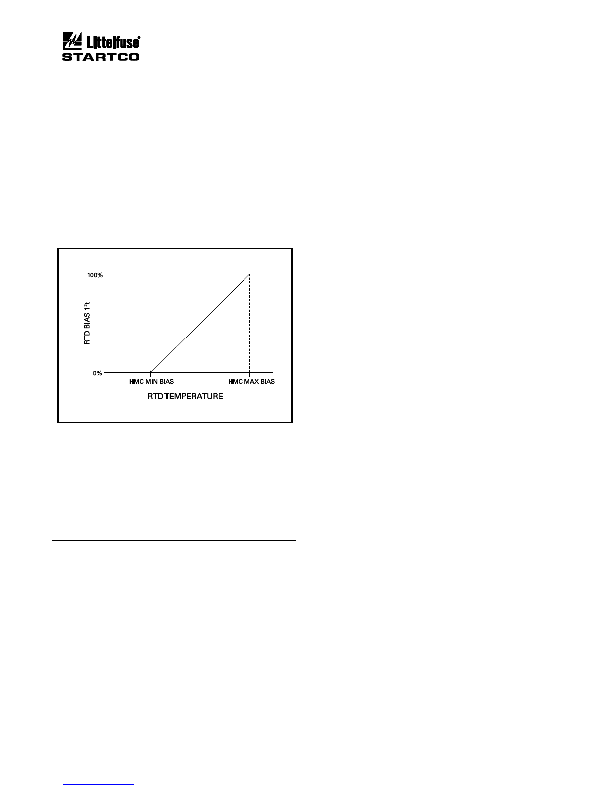
Page 5-10
MPS Motor Protection System Rev. 6-F-022117
Protective Functions
5.28 HOT-MOTOR COMPENSATION
OPI Menu: Setup | Protection | RTD Temperature
If hot-motor compensation (HMC) is enabled, the
maximum stator-RTD temperature is used to bias the
thermal model by increasing Used I2t when the RTD
temperature is greater than the thermal-model
temperature.
Two set points are used to define the compensation.
See Fig. 5.3. HMC Minimum Bias is the stator
temperature where compensation begins at 0% I2t. HMC
Maximum Bias is the stator temperature where
compensation ends at 100% I2t.
Although the bias calculation is based on 0% and 100%
I2t values, the Used I2t adjustment is limited to 90% I2t.
An actual overload condition is required to cause a trip at
100% I2t.
FIGURE 5.3 Used I2t Bias Curve.
HMC Minimum Bias ............ 40.00 to 200.00°C (104°F to
392°F)
HMC Maximum Bias ........... 40.00 to 200.00°C (104°F to
392°F)
Protection .............................. Enable/Disable
NOTE: Hot-motor compensation will not be active unless
the HMC High set point is at least 10°C above the HMC
Low set point.
5.29 ANALOG INPUT
OPI Menu: Setup | Analog Input | 4–20 Input Type
The analog input function is selectable as Metering
Only, Protection, Sync to ASD, or Motor Speed.
5.29.1 PROTECTION
OPI Menu: Setup | 4-20 Analog In | Protection
The protection input has high-level and low-level trip
and alarm set points. A high-level trip or alarm occurs
when the 4-20-mA input exceeds the high-level trip or
alarm set point, and a low-level trip or alarm occurs when
the 4-20-mA input is lower than the low-level trip or
alarm set point.
Trip action is fixed at Trip1 and alarm action is fixed at
Alarm1.
High Level Trip .................... 0.10 to 20.00 mA
Low Level Trip ..................... 0.10 to 20.00 mA
Trip Delay ............................. 0.01 to 100.00 s
High Level Alarm ................. 0.10 to 20.00 mA
Low Level Alarm ................. 0.10 to 20.00 mA
Alarm Delay ......................... 0.01 to 100.00 s
5.29.2 SYNCHRONIZE TO ASD
OPI Menu: Setup | 4-20 Analog In | Sync to ASD
When Sync to ASD is selected, the MPS uses the
4-20-mA input to set the internal sampling rate for current
and voltage inputs so that protection and metering
functions use accurate RMS and DFT values from 10.00
to 70.00 Hz.
4-mA Frequency (lower) ...... 0.00 to 70.00 Hz
20-mA Frequency (upper) .... 0.00 to 70.00 Hz
Frequency Range .................. 10.00 to 70.00 Hz
5.29.3 MOTOR SPEED
OPI Menu: Setup | 4-20 Analog In | Motor Speed
When the analog-input type is selected as Motor Speed,
the 4-20-mA analog input is used as the speed input. This
selection overrides the selections for the high-speed
tachometer input and failure-to-accelerate protection uses
the analog input as the source of speed information.
4-mA Speed .......................... 0.00 to 100% Sync Speed
20-mA Speed ........................ 0.00 to 100% Sync Speed
5.29.4 METERING ONLY
When the analog-input type is selected as Metering
Only, an analog input does not affect MPS operation, but
its value can be observed in the Metering menu and with a
communications network.
Page 57
Page 6-1
MPS Motor Protection System Rev. 6-F-022117
Starter Functions
6. STARTER FUNCTIONS
OPI Menu: Setup | Starter
6.1 GENERAL
All common starter types are supported. From the OPI
Starter Type menu, select one of seventeen starter types or
select Protection Only. Starter types requiring two FLA
settings are indicated by the “x” symbol in the OPI
display.
When Protection Only is selected, all starter functions
except STOP are disabled and all OPI control-select
LED’s will be off. Any STOP signal will initiate a Trip1
when the MPS is in Protection Only.
NOTE: When Protection Only is selected, STOP will not
function if Trip1 is not assigned to a relay output.
When Protection Only is selected, the OPI STOP and
RUN LED’s are controlled by motor current. When
motor current is below the minimum Current Threshold
defined in Section 3.2.1.2, the STOP LED is on and RUN
LED is off. When motor current is above the minimum
Current Threshold, the STOP LED is off and RUN LED
is on. When a starter type is selected, the STOP and RUN
LED’s are under starter control and not based on motor
current.
When a starter type is selected, starter control can be
performed with the digital inputs, OPI, or network
communications. See Section 4.3.3 for details on
selecting start sources.
Three control modes are available and selected using
the OPI CONTROL SELECT key. In addition, a digital
input can be used to select LOCAL. Each control mode
has specific start sources that can be programmed as
shown in Table 6.1. REMOTE control can be configured
to operate with start sources from the digital input, OPI
and the network. OPI Control uses the OPI start keys as
the start sources. LOCAL control uses the Local Start1 or
Local Start2 start sources or the OPI. In LOCAL mode,
OPI control can be enabled or disabled. Control selection
is indicated by the REMOTE, OPI, and LOCAL LED’s
on the OPI.
The digital inputs allow concurrent operation of three
start-control methods; 3-wire start/stop, 2-wire start/stop,
and 3-wire local start/stop. Three-wire control requires
two digital inputs, one programmed for Start1 or Start2
(N.O. momentary start switch) and one programmed for
Stop (N.C. momentary stop switch) as shown in Fig. 6.1.
Two-wire control uses one input, programmed as 2-Wire
Start1 or 2-Wire Start2, for start/stop control and can be
used where a single contact provides start/stop operation.
See Fig. 6.2. If a start was activated by a 2-wire start
input, any other STOP will initiate a latching Trip1. In all
other cases, STOP does not cause a trip.
Digital inputs programmed for Limit1 Stop and Limit2
Stop are used to provide stop control for Start1 and
Start2. This is typically used in reversing starter
applications. The forward-direction limit switch is
connected to the Limit1 Stop input and the reversedirection limit switch is connected to the Limit2 Stop
input.
With this control method, a Start1 requires limit switch
1 to be closed and limit switch 2 is ignored. In a similar
manner, Start2 requires, limit switch 2 to be closed while
limit switch 1 is ignored.
NOTE: When starter functions are used, protective
functions with the trip action set to Trip1 will cause the
starter to stop when a trip occurs. Reset is required.
Table 6.1 indicates the available start sources.
TABLE 6.1 START-SOURCE SUMMARY
(1)
CONTROL
(7)
SELECTION
START SOURCE
REMOTE
(2)
DIGITAL
INPUTS
(3)
Start1 Input (3-wire control)
Start2 Input (3-wire control)
2-W Start1 (2-wire control)
(4)
2-W Start2 (2-wire control)
(4)
OPI
(3)
START1 Key
START2 Key
NETWORK
(3)
Start1 Command
Start2 Command
OPI
OPI START1 Key
OPI START2 Key
LOCAL
(5) (6)
DIGITAL
INPUTS
Local Start1 (3-wire)
Local Start2 (3-wire)
OPI
(8)
START1 Key
START2 Key
(1)
All STOP sources are always enabled.
(2)
Factory default has all sources enabled and REMOTE
selected.
(3)
Can be enabled or disabled using the Setup | Starters |
Remote Group menu.
(4)
STOP causes a latching trip.
(5)
LOCAL can also be selected by a network command
or by a digital input programmed for Local Select.
Each Local Select source must de-select local control
for the MPS to return to the previous control setting.
(6)
I2t Start Inhibit, Starts per Hour alarms and Interlocks
are bypassed.
(7)
At least one Control Selection must be enabled even
when Protection Only is selected.
(8)
Can be enabled or disabled using the Setup | Starters
| Local Group menu.
Up to four timers (Stage 1 to 3 Delay, and Start Time)
control the start sequence. These timers control Starter
RLYA, Starter RLYB, Starter RLYC, and Starter RLYD as
shown in the timing diagrams in Section 6.2. These
functions can be assigned to any output relay. Digital
Page 58

Page 6-2
MPS Motor Protection System Rev. 6-F-022117
Starter Functions
inputs can be programmed to monitor contactor status.
Contactor status corresponding to Starter RLYA, Starter
RLYB, Starter RLYC, and Starter RLYD outputs are
designated as RLYA Status, RLYB Status, RLYC Status,
and RLYD Status. The MPS will issue a Trip1 and
indicate Relay Status Trip if the status contact does not
follow within 500 ms of the command to operate the
respective relay output. In addition, a transition must not
occur prior to its intended time.
When the starting sequence is complete, contactor
status is checked every 500 ms and a Relay Status Trip
will occur if the status changes.
NOTE: Relay Status is not checked when the starter is in
the stopped state.
The Start Time set point is the maximum start time
allowed. The starting process will terminate and generate
a Trip1 unless current is between 1.5 x (CT-Primary
Rating / FLA) and 125% FLA when the Start Time timer
times out.
In reduced-voltage-starting applications, the MPS can
use time-based or current-based transfer from the starting
to the running connection. The transfer type is selected as
Time Transfer or Current Transfer using the Transfer
Type menu.
When Current Transfer is selected, the start-connection
delay (Stage 1 Delay or Stage 2 Delay, see Table 6.2 and
Figs 6.5, 6.6, 6.7, and 6.8) defines the minimum startingconnection time. The transfer to the run connection
occurs when the start-connection delay has expired and
current is below the Transfer Current. When current is
above the Transfer Current, the transfer will be delayed
up to the maximum time defined by the Start Time. If
current is below 1.5 x (CT-Primary Rating / FLA) when
the start-connection delay expires or if the Start Time is
exceeded, the MPS will issue a Trip1 and indicate Starter
Trip.
When Time Transfer is selected, the start-connection
delay set point (Stage 1 Delay or Stage 2 Delay) is used to
determine the transfer time. Transfer to the run
connection occurs after the start-connection delay has
expired.
In both current- and time-transfer modes, the MPS will
issue a Trip1 and indicate Starter Trip if load current is
above 125% FLA or below 1.5 x (CT-Primary Rating /
FLA) when the Start Time expires. The Start Time set
point must be long enough to allow the starting sequence
to complete and for the motor current to drop below 125%
FLA.
Table 6.2 summarizes starter types and shows which
starter set points are active.
The backspin timer is available when a delay is
required between starts. The backspin timer is enabled in
the BkSpin En/Disable menu, and the delay time is set in
the Backspin Delay menu. The backspin timer is
activated by a STOP or when supply voltage is cycled on
the MPS. While the backspin timer is on, the Backspin
Timer On message is displayed in the Status Message
menu and starts are not allowed.
The connection diagrams, Figs. 6.9 to 6.23, show
typical control circuits with 120-Vac contactor coils and
the 24-Vdc source on the MPS-CTU used for status
contacts. Other supply voltages can be used within the
limits of the digital-input and relay-contact ratings. The
use of status contacts is optional.
NOTE: Stop and start control, electrical interlocks, and
mechanical interlocks are not shown in connection
diagrams.
NOTE: Connection diagrams show typical output relay
assignments that must be set using the Setup ⏐ Relay
Outputs ⏐ Relay x ⏐ Relay x Function menu.
NOTE: To cancel a long backspin time, enter new backspin
parameters and restart the MPS using the Setup | System
Config | Maintenance | Restart MPS-CTU menu or cycle
supply voltage.
Page 59
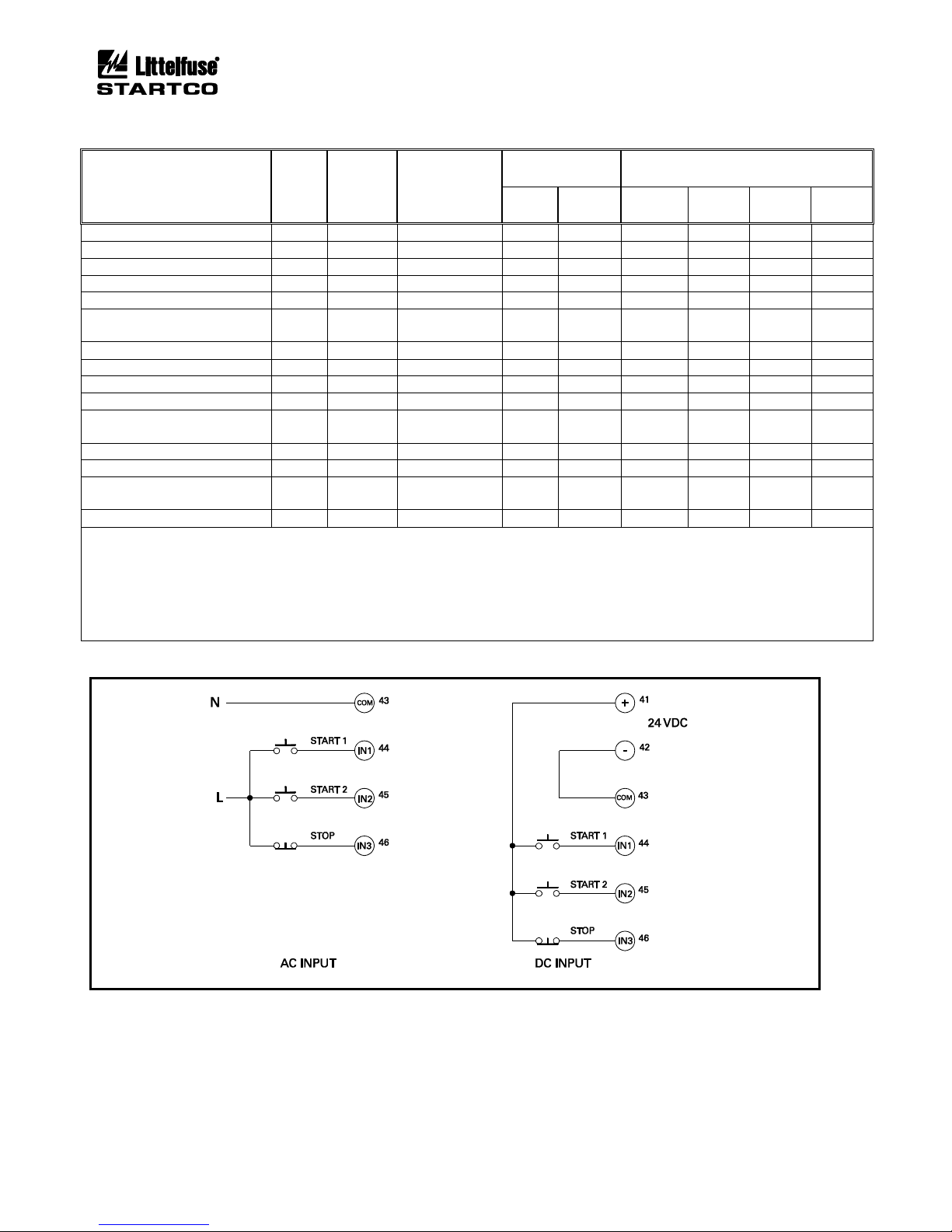
Page 6-3
MPS Motor Protection System Rev. 6-F-022117
Starter Functions
TABLE 6.2 STARTER SUMMARY
STARTER TYPE
SEQ.
NO.
TIMERS
USED
(1)
START-
CONNECTION
TIMER
NUMBER
(1)
ACTIVE FLA
SETPOINTS
(2)
RELAYS AND CONTACTOR STATUS
(3)
FLA
FLA 2
RLYA
RLYB
RLYC
RLYD
Full-Voltage Non-Reversing
1 4 x x
Adjustable-Speed Drive
1 4 x x
Soft-Start
1 4 x x
Full-Voltage Reversing
2 4 x x x
Two-Speed Two-Winding
2 4 x x x x
Reactor or Resistor ClosedTransition
(4)
3
1,4 1 x x x
Slip-Ring
(4)
3
1,4 1 x x x Part-Winding
(4)
3
1,4 1 x x x x
Double-Delta
(4)
3
1,4 1 x x x x
Soft-Start-with-Bypass
(4)
3
1,4 1 x x x
Reactor or Resistor OpenTransition
(4)
4
1,4 1 x x x
Two-Winding
(4)
4
1,4 1 x x x x Wye-Delta Open-Transition
(4)
5
1,2,3,4
2
x x x x x
Autotransformer ClosedTransition
(4)
5
1,2,3,4
2 x x x x
Wye-Delta Closed-Transition
(4)
6
1,2,4 2 x x x x x
x
(1)
TIMERS
1: Stage 1 Delay
2: Stage 2 Delay
3: Stage 3 Delay
4: Start Time
(4)
Current transfer capability when enabled
(2)
FLA SETPOINTS
FLA: Full-Load Current
FLA2: Full-Load Current 2
(3)
RELAYS AND CONTACTOR STATUS
Starter RLYA, Starter RLYB, Starter RLYC, and
Starter RLYD are not automatically assigned. The
user must assign these functions to individual relays.
Status is assignable to any digital input.
FIGURE 6.1 Typical 3-Wire Control.
Page 60
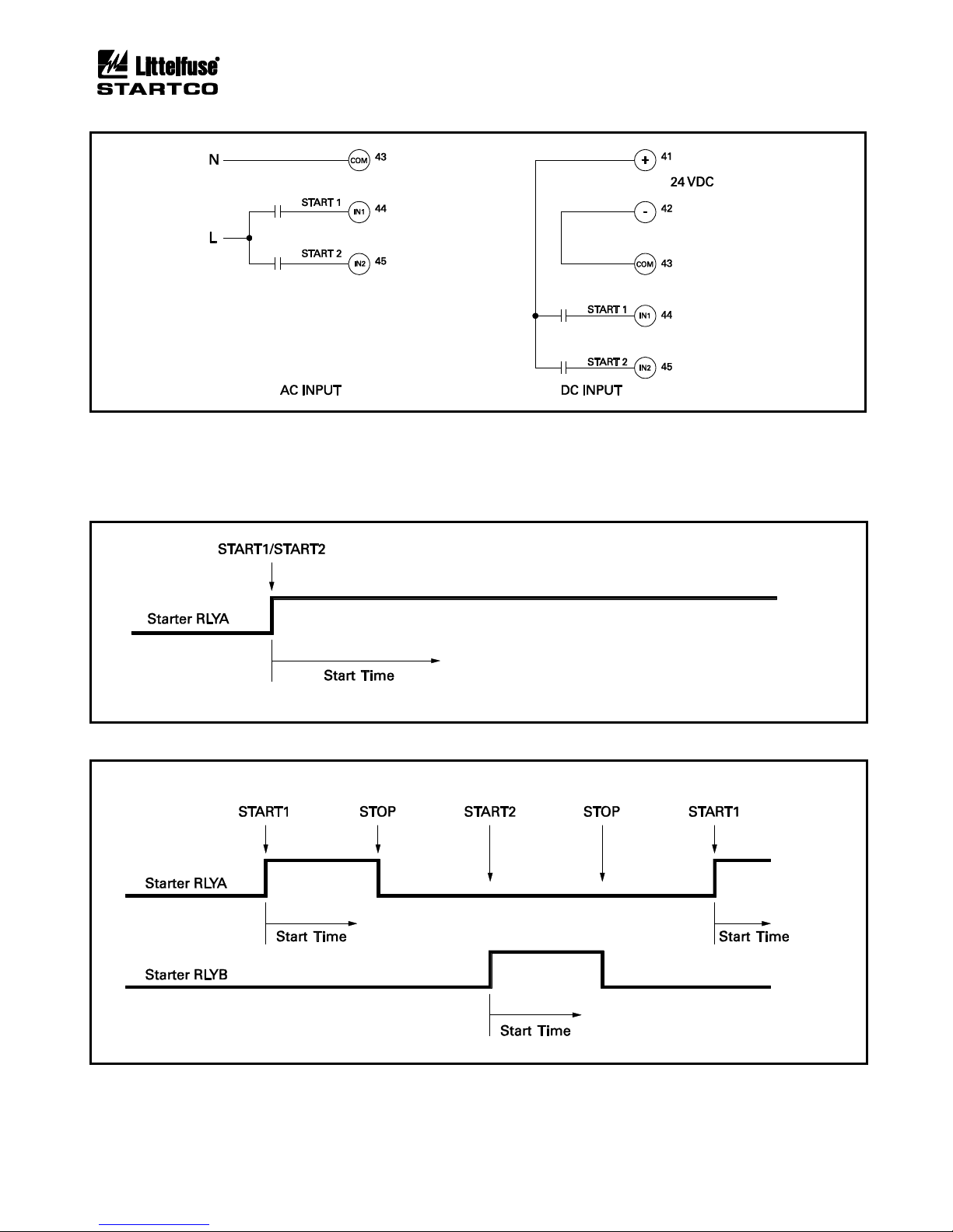
Page 6-4
MPS Motor Protection System Rev. 6-F-022117
Starter Functions
FIGURE 6.2 Typical 2-Wire Control.
6.2 STARTER TIMING SEQUENCES
The MPS uses one of six timing sequences to implement the various starter types. These time-based starter sequences
are shown in Figs. 6.3 to 6.8.
FIGURE 6.3 Starter Sequence 1.
FIGURE 6.4 Starter Sequence 2.
Page 61
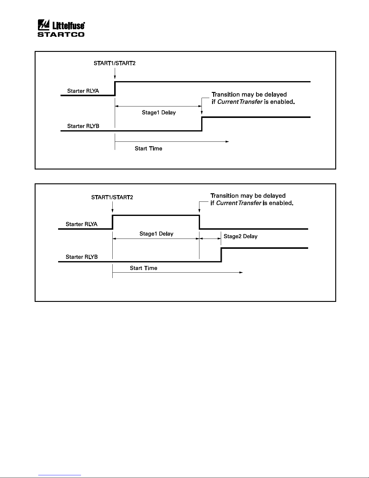
Page 6-5
MPS Motor Protection System Rev. 6-F-022117
Starter Functions
FIGURE 6.5 Starter Sequence 3.
FIGURE 6.6 Starter Sequence 4.
Page 62
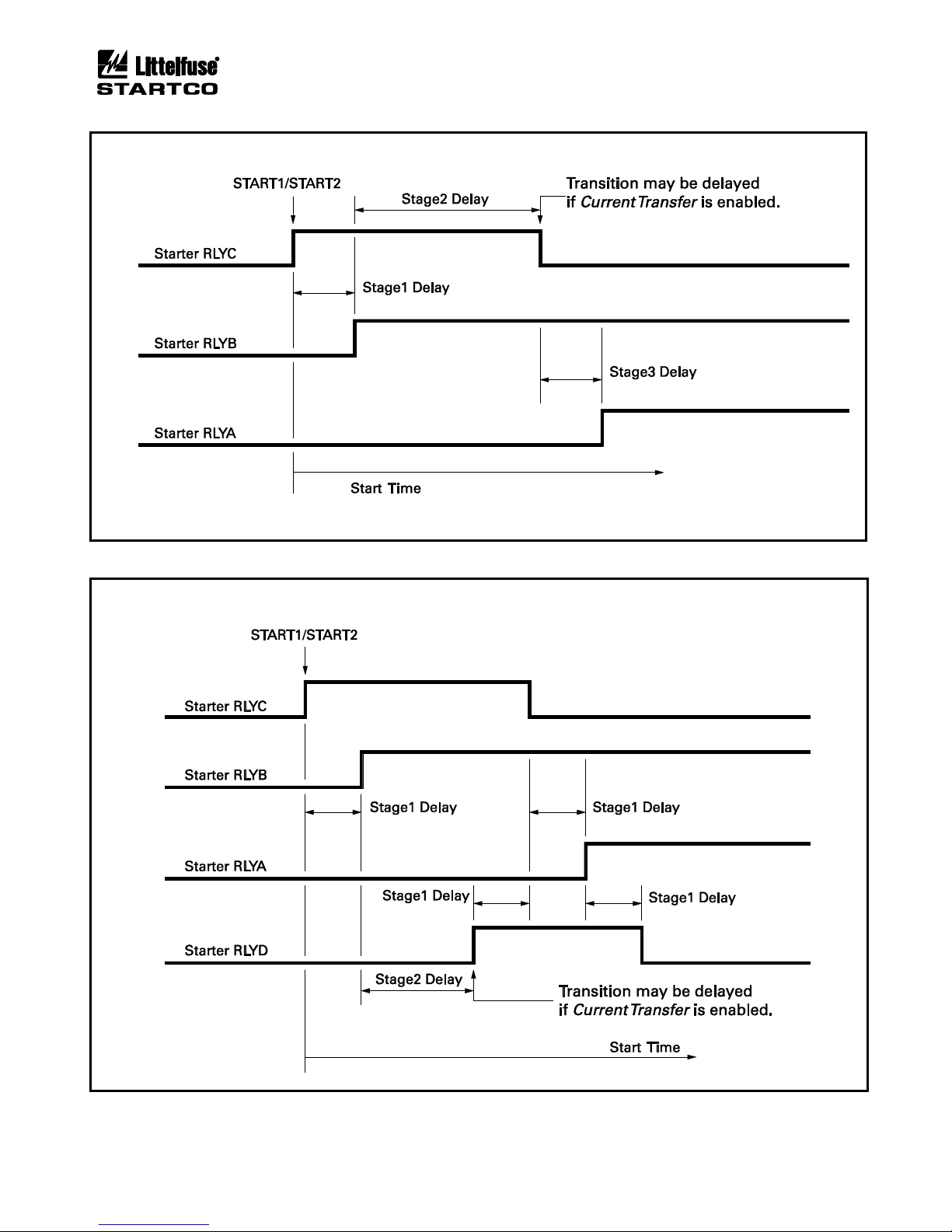
Page 6-6
MPS Motor Protection System Rev. 6-F-022117
Starter Functions
FIGURE 6.7 Starter Sequence 5.
FIGURE 6.8 Starter Sequence 6.
Page 63
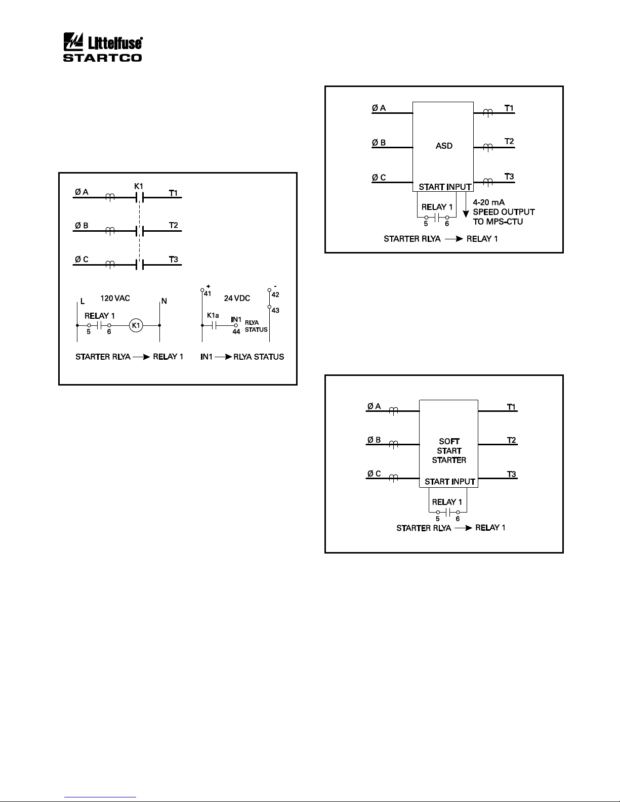
Page 6-7
MPS Motor Protection System Rev. 6-F-022117
Starter Functions
6.3 FULL-VOLTAGE NON-REVERSING STARTER
Sequence: Fig. 6.3
Connection: Fig. 6.9
Current Transfer: Not available
START1 or START2 is the start command and Starter
RLYA is used as the output to control the contactor.
FIGURE 6.9 Full-Voltage Non-Reversing-Starter
Connection.
6.4 ADJUSTABLE-SPEED DRIVE
Sequence: Fig. 6.3
Connection: Fig. 6.10
Current Transfer: Not available
The MPS-CTU provides the start input to an
adjustable-speed drive (ASD). START1 or START2 is
the start command and Starter RLYA is used as the output
to control the ASD.
The MPS-CTU has a 4-20 mA input that should be
used to synchronize its sampling rate to the ASD output
frequency so that all protection and metering values are
valid for an ASD output frequency from 10 to 70 Hz. In
ASD applications, voltage and current inputs must be
derived from the load side of the ASD, and undervoltage
protection must be disabled.
FIGURE 6.10 Adjustable-Speed-Drive Connection.
6.5 SOFT-START STARTER
Sequence: Fig. 6.3
Connection: Fig. 6.11
Current Transfer: Not available
The MPS-CTU provides the start input to a solid-state
starter. START1 or START2 is the start command and
Starter RLYA is used as the output to control the starter.
FIGURE 6.11 Soft-Start-Starter Connection.
Page 64
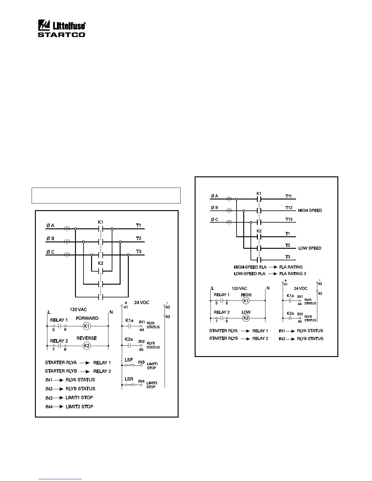
Page 6-8
MPS Motor Protection System Rev. 6-F-022117
Starter Functions
6.6 FULL-VOLTAGE REVERSING STARTER
Sequence: Fig. 6.4
Connection: Fig. 6.12
Current Transfer: Not available
The full-voltage reversing starter uses START1 to
activate Starter RLYA for forward control and START2 to
activate Starter RLYB for reverse control. RLYA Status is
the status corresponding to Starter RLYA and RLYB Status
is the status corresponding to Starter RLYB.
For OPI and 3-wire start/stop control, a direction change
requires a STOP command prior to a START1 or START2
command. For 2-wire control a STOP command is not
required.
Fig. 6.12 shows the use of forward and reverse limit
switches. When Start1 is issued, K1 is energized. If a
STOP is issued or LSF opens, K1 is de-energized. Provided
LSR is closed, Start2 will energize K2 to allow operation in
the reverse direction.
NOTE: Phase CT’s should be located upstream of the
contactors.
FIGURE 6.12 Full-Voltage-Reversing-Starter
Connection.
6.7 TWO-SPEED STARTER
Sequence: Fig. 6.4
Connection: Fig. 6.13, 6.14, and 6.15
Current Transfer: Not available
The two-speed starter uses START1 to activate Starter
RLYA for high-speed control and START2 to activate
Starter RLYB for low-speed control. RLYA Status is the
status corresponding to Starter RLYA and RLYB Status is
the status corresponding to Starter RLYB. A speed
change requires a STOP command prior to a START1 or
START2 command. This starter can be used on motors
with two separate windings (Fig. 6.13) or on motors with
reconnectable windings (Figs. 6.14 and 6.15).
This starter requires two FLA settings. Use FLA
Rating for the high-speed connection and FLA Rating 2
for the low-speed connection.
FIGURE 6.13 Two-Speed Two-Winding-Starter
Connection.
Page 65
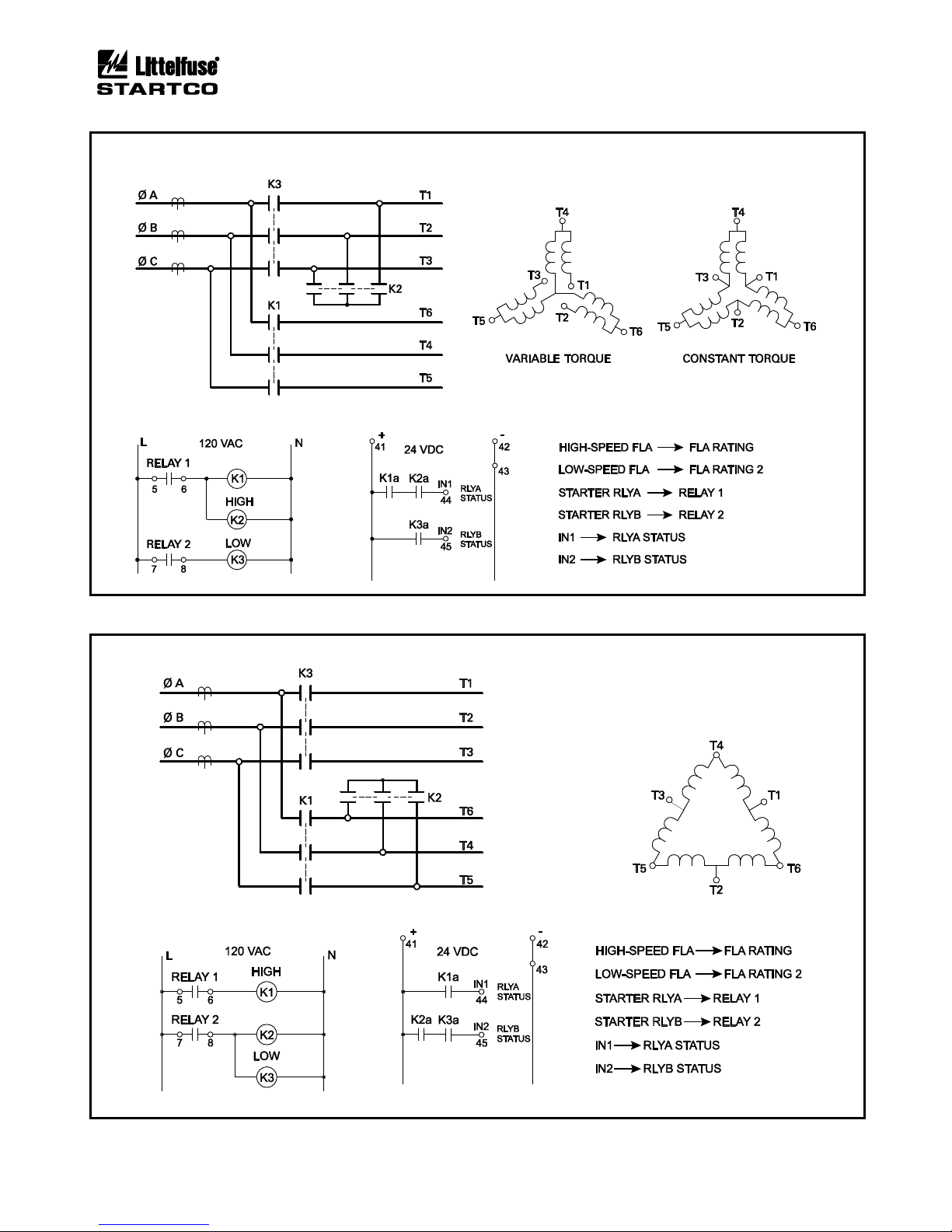
Page 6-9
MPS Motor Protection System Rev. 6-F-022117
Starter Functions
FIGURE 6.14 Two-Speed Constant- and Variable-Torque-Starter Connections.
FIGURE 6.15 Two-Speed Constant-Horsepower-Starter Connection.
Page 66
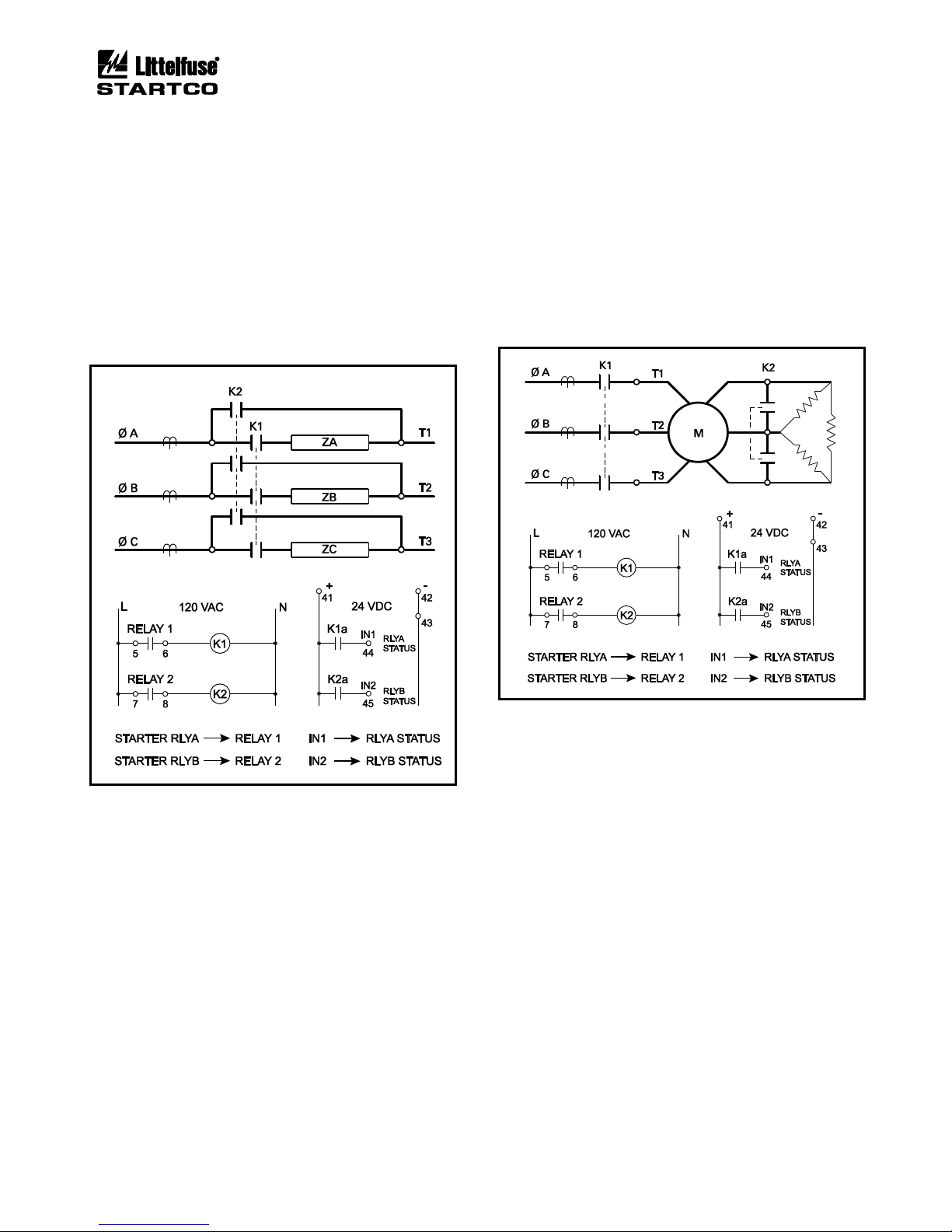
Page 6-10
MPS Motor Protection System Rev. 6-F-022117
Starter Functions
6.8 REACTOR OR RESISTOR CLOSED-TRANSITION
STARTER
Sequence: Fig. 6.5
Connection: Fig. 6.16
Current Transfer: Available
This starter uses a reactor or resistor to provide
reduced-voltage starting and the reactor or resistor
contactor (K1) remains closed during running.
START1 or START2 initiates the starting sequence by
activating Starter RLYA. Starter RLYB activates after the
Stage1 Delay.
FIGURE 6.16 Reactor or Resistor-Starter Connection.
6.9 SLIP-RING STARTER
Sequence: Fig. 6.5
Connection: Fig. 6.17
Current Transfer: Available
The slip-ring starter is a single-stage wound-rotor
starter with a single contactor (K2) controlling the rotor
resistor bank.
START1 or START2 initiates the starting sequence by
activating Starter RLYA. Starter RLYB activates after the
Stage1 Delay.
FIGURE 6.17 Slip-Ring-Starter Connection.
Page 67
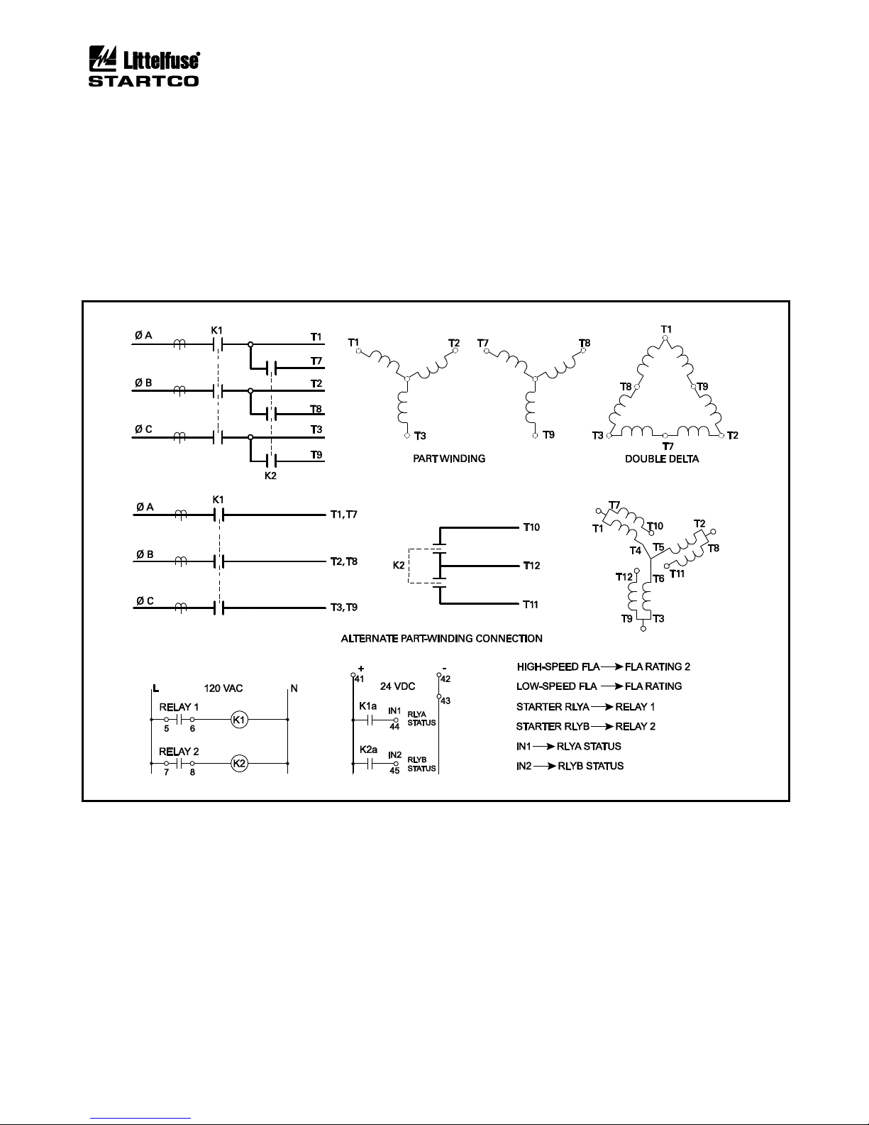
Page 6-11
MPS Motor Protection System Rev. 6-F-022117
Starter Functions
6.10 PART-WINDING AND DOUBLE-DELTA STARTERS
Sequence: Fig. 6.5
Connection: Fig. 6.18
Current Transfer: Available
The part-winding starter is used on motors with two
stator windings and the double-delta starter has a delta
winding that is parallel connected during running.
START1 or START2 initiates the starting sequence by
activating Starter RLYA. Starter RLYB activates after the
Stage1 Delay.
Both starters require two FLA settings. FLA Rating 2
is the full-load current for the starting connection and
FLA Rating is the full-load current for the running
connection.
FIGURE 6.18 Part-Winding and Double-Delta-Starter Connections.
Page 68
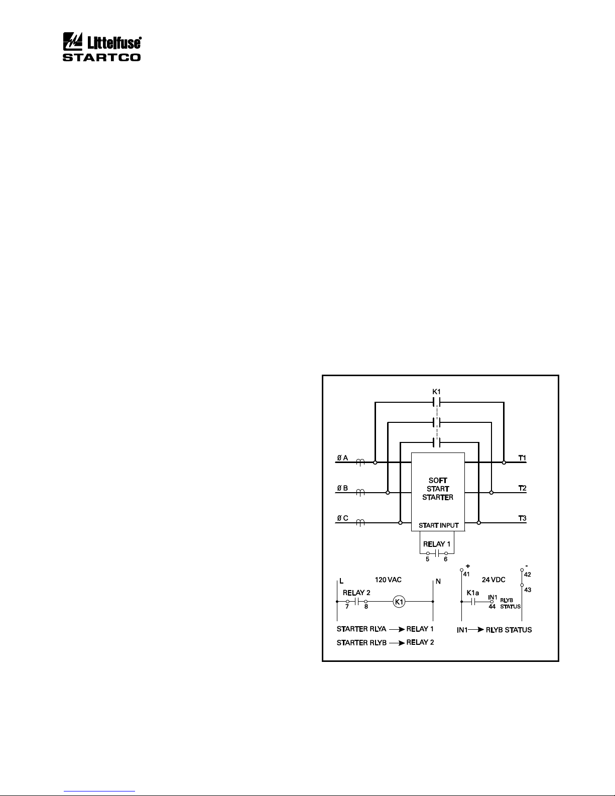
Page 6-12
MPS Motor Protection System Rev. 6-F-022117
Starter Functions
6.11 SOFT-START-WITH-BYPASS STARTER
Sequence: Fig. 6.5
Connection: Fig. 6.19
Current Transfer: Available
START1 or START2 initiates the starting sequence by
activating Starter RLYA. Starter RLYB activates after the
Stage1 Delay to close the bypass contactor.
Although RLYA Status can be selected as a digital
input, it is not usually available for this starter.
For a soft-start where the bypass function is included, a
bypass signal from the soft-start can be used as an input to
the MPS. There are two solutions:
1) This option coordinates the MPS Starter RLYB
signal with the soft-start and ensures the status
input does not validate prior to the intended time.
Assign an MPS output relay with the Starter
RLYB function as per Fig. 6.19. Connect this
output-relay contact in series with the bypass
contact from the soft-start (K1a) and connect this
signal to a digital input programmed as RLYB
Status. Set the Stage 1 Delay longer than the
soft-start bypass time.
2) This option uses a digital input programmed as
Trip1 in conjunction with the MPS trip-bypass
feature. Connect the bypass signal from the softstart to a digital input assigned as Trip1. Enable
Trip Bypass and set the Bypass Delay longer than
the start time of the soft-start. Note that this
feature is based on current and during a stop
requires the input to remain valid until current is
not detected. If the soft-start has a ramp-down
feature, set the INx Trip Delay greater than the
ramp-down time to prevent a trip when the softstart stops. See Section 4.2.8.
6.12 REACTOR OR RESISTOR OPEN-TRANSITION
STARTER
Sequence: Fig. 6.6
Connection: Fig. 6.16
Current Transfer: Available
START1 or START2 activates Starter RLYA for the
duration of the Stage1 Delay. After Starter RLYA deactivates for the Stage2 Delay, Starter RLYB activates.
6.13 TWO-WINDING STARTER
Sequence: Fig. 6.6
Connection: Fig. 6.20
Current Transfer: Available
This starter is an open-transition starter for twowinding motors that run with only one winding energized.
START1 or START2 activates Starter RLYA for the
time specified by the Stage1 Delay. After Starter RLYA
de-activates for the Stage2 Delay, Starter RLYB activates.
This starter requires two full-load current set points.
FLA Rating 2 is the full-load current for the starting
connection (Starter RLYA) and FLA Rating is the full-load
current for the running connection (Starter RLYB).
6.14 WYE-DELTA OPEN-TRANSITION STARTER
Sequence: Fig. 6.7
Connection: Fig. 6.21
Current Transfer: Available
START1 or START2 initiates the sequence. Starter
RLYC activates to close the neutral contactor (K3).
Starter RLYB activates the wye contactor (K2) after the
Stage1 Delay. Starter RLYC de-activates to open the
neutral contactor after the Stage2 Delay and Starter RLYA
activates to close the delta contactor (K1) after the Stage3
Delay. Stage-1 and Stage-3 delays are contactor-transfer
times and should be set in the range of 0.1 to 0.5 seconds.
Locate CT’s on the line side of the starter.
This starter uses two full-load current settings. Set FLA
Rating to the delta full-load current and FLA Rating 2 to
the wye full-load current.
FIGURE 6.19 Soft-Start-With-Bypass-Starter
Connection.
Page 69
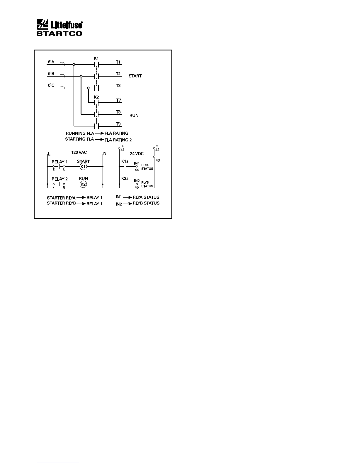
Page 6-13
MPS Motor Protection System Rev. 6-F-022117
Starter Functions
FIGURE 6.20 Two-Winding-Starter Connection.
6.15 AUTOTRANSFORMER CLOSED-TRANSITION
STARTER
Sequence: Fig. 6.7
Connection: Fig. 6.22
Current Transfer: Available
START1 or START2 initiates the sequence. Starter
RLYC activates to close the neutral contactor (K3) on the
autotransformer. Starter RLYB activates to close the main
autotransformer contactor (K2) after the Stage1 Delay.
Starter RLYC de-activates to open the autotransformer
neutral contactor after the Stage2 Delay, and Starter
RLYA activates to close the main motor contactor (K1)
after the Stage3 Delay. Stage-1 and Stage-3 delays are
contactor-transfer times and should be set in the range of
0.1 to 0.5 seconds.
6.16 WYE-DELTA CLOSED-TRANSITION STARTER
Sequence: Fig. 6.8
Connection: Fig. 6.23
Current Transfer: Available
START1 or START2 initiates the start sequence.
Starter RLYC activates to close the neutral contactor (K3).
Starter RLYB activates to close the wye contactor (K2)
after the Stage1 Delay. Starter RLYD activates to close
the resistor contactor (K4) after the Stage2 Delay. This is
followed by de-activation of Starter RLYC, activation of
Starter RLYA to close the main motor contactor (K1), and
de-activation of Starter RLYD, all displaced by the Stage1
Delay.
Locate CT’s on the line side of the starter. Set FLA
Rating to the delta full-load current and FLA Rating 2 to
the wye full-load current. Stage-1 delay is a contactortransfer time and should be set in the range of 0.1 to 0.5
seconds.
Page 70
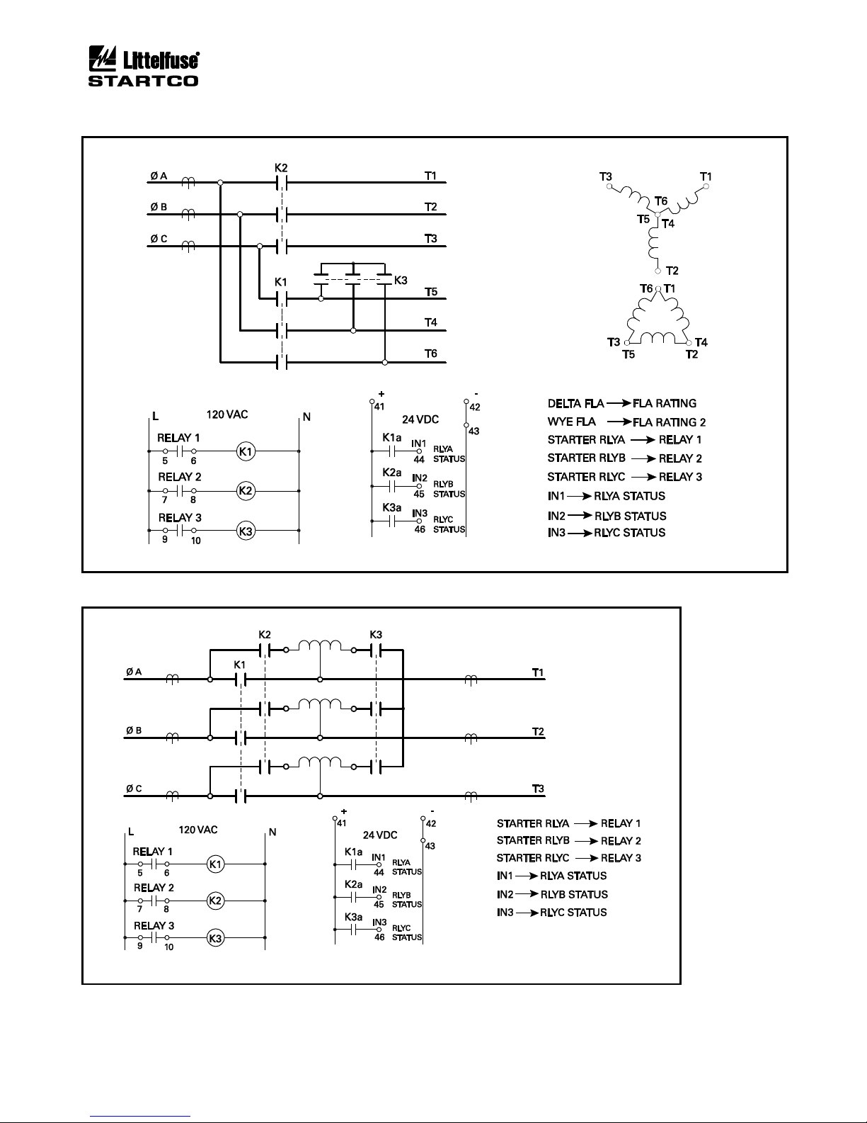
Page 6-14
MPS Motor Protection System Rev. 6-F-022117
Starter Functions
FIGURE 6.21 Wye-Delta Open-Transition-Starter Connection.
FIGURE 6.22 Autotransformer Closed-Transition-Starter Connection.
Page 71
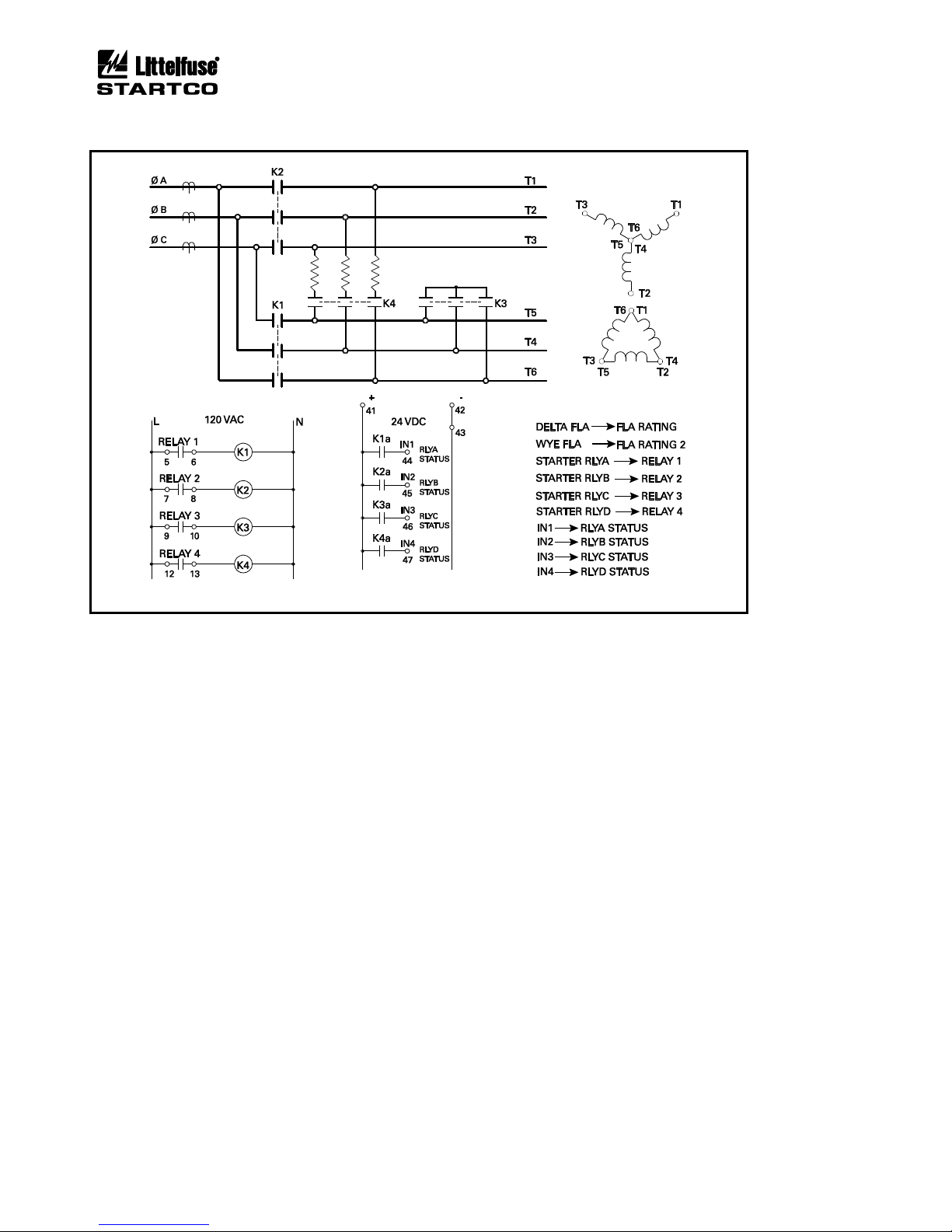
Page 6-15
MPS Motor Protection System Rev. 6-F-022117
Starter Functions
FIGURE 6.23 Wye-Delta Closed-Transition-Starter Connection.
Page 72

Page 6-16
MPS Motor Protection System Rev. 6-F-022117
Starter Functions
This page intentionally left blank.
Page 73

Page 7-1
MPS Motor Protection System Rev. 6-F-022117
Theory of Operation
7. THEORY OF OPERATION
7.1 SIGNAL-PROCESSING ALGORITHMS
The sampling frequency of the MPS is variable. It can
be set for 50-Hz, 60-Hz, or variable-frequency
applications. The MPS obtains sixteen samples per cycle
of each current and voltage signal. For an adjustablespeed drive (ASD) application, a speed or frequency
output from the ASD can be connected to the 4-20-mA
input to synchronize the sampling rate to the ASD output
frequency. This maintains accurate measurements of
power and sequential components.
The sampling rate is sixteen samples per cycle of the
fundamental frequency. A Discrete-Fourier-Transform
(DFT) algorithm is used to obtain the magnitude and
phase angles of the fundamental-frequency components of
the current and voltage waveforms. These values provide
true positive- and negative-sequence components. True
RMS values of line currents are calculated for use by the
thermal-model algorithm. RMS values include up to the
8th harmonic. All calculated values are updated at the
sampling frequency to achieve a fast response to fault
conditions. RMS values of the fundamental components
of current and voltage are displayed.
The MPS uses the input voltage VA for frequency
measurement. The input voltage must be above 30 Vac
and a sixteen-cycle interval is used to determine
frequency. Frequency protection is inhibited when system
voltage is less than 50% of the System Voltage setting.
7.2 POWER ALGORITHM
Apparent power (S) is calculated by:
jQPS +=
Real power (P) is determined from the in-phase
components of I and V, and reactive power (Q) is
determined from the quadrature components of I with
respect to V. Power factor is the magnitude of the ratio of
P to S.
The one-PT connection assumes balanced voltages for
power calculations. Power calculations for the other
connections are valid for both balanced and unbalanced
conditions. In all cases, power calculations use the twowattmeter method and assume 3-wire loads.
The IEEE convention is used for power displays:
+Watts, +Vars, -PF (Lag) Importing Watts,
Importing Vars
+Watts, -Vars, +PF (Lead) Importing Watts,
Exporting Vars
-Watts, -Vars, -PF (Lag) Exporting Watts,
Exporting Vars
-Watts, +Vars, +PF (Lead) Exporting Watts,
Importing Vars
7.3 OPERATOR INTERFACE (MPS-OPI)
The OPI is a terminal device used to communicate with
the MPS-CTU. All set points, operating parameters, and
menus are stored in the MPS-CTU.
The OPI contains a microprocessor used to
communicate with the MPS-CTU, read key presses, and
perform display functions.
On multiple-OPI systems, all OPI’s display the same
information. Key presses on any OPI will be processed
by the MPS-CTU.
7.4 RTD MODULE (MPS-RTD)
The RTD module contains a microprocessor, A/D
converter, and analog multiplexers used to measure up to
eight RTD’s. The RTD-measuring circuit is isolated from
the I/O Module network. All eight RTD’s are scanned
every three seconds. RTD linearization, open/short
detection, and lead compensation are performed by the
RTD module. RTD temperature is sent to the MPS-CTU
where temperature monitoring occurs.
7.5 DIFFERENTIAL MODULE (MPS-DIF)
The differential module obtains 32 samples per cycle of
the differential current. A Discrete-Fourier-Transform
(DFT) algorithm is used to obtain the magnitude of the
three differential currents. Frequency of operation is set
by the MPS-CTU unit and allows differential protection to
be used in variable-frequency drive applications. The
DFT values are sent to the MPS-CTU where differential
protection is performed.
7.6 FIRMWARE DIAGNOSTICS
Starting with firmware 2.01, diagnostic error handling
has been added. In the event of an internal fault, a
diagnostic error code is generated and can be viewed with
the OPI. The last error code can be viewed by selecting
Setup ç System Config ç Maintenance ç Firmware Version.
The diagnostic code is a two or three digit hexadecimal
number.
02 to FF: Processor Fault
100: Protection-Algorithm Fault
200: Relay-Control Algorithm Fault
300: Starter-Control Fault
400: Menu-Display Fault
500: OPI-Key-Handler Fault
600: Real-Time Clock Fault
700: Communication-Handler Fault
800: RTD Temperature-Handler Fault
900: A/D Communication-Interface Fault
The last diagnostic error code is saved in non-volatile
memory. The diagnostic code is overwritten by any new
codes but can also be manually set to zero. To clear the
error code, press RESET while in the Firmware Version
menu.
Page 74

Page 7-2
MPS Motor Protection System Rev. 6-F-022117
Theory of Operation
When upgrading an MPS that did not previously
support the diagnostic error code, the initial value of the
diagnostic code is not valid and should be cleared.
A diagnostic error generates a Trip1 and increments the
trip counter; however, a trip record is not generated.
Page 75

Page 8-1
MPS Motor Protection System Rev. 6-F-022117
Personal Computer Interface
8. COMMUNICATIONS
8.1 PERSONAL-COMPUTER INTERFACE
8.1.1 FIRMWARE UPGRADE
The MPS-CTU control program is stored in flash
memory. Field updates can be made through the I/O
module communications connection. The following are
required:
• A WindowsÒ PC with the SE-Flash program installed
• A file containing the MPS-CTU control program (.s19
file)
• An RS-232/RS-485 converter that operates at 57,600
bit/s. Use the Littelfuse Startco SE-485-PP or
SE-485-DIN.
SE-Flash is available at www.littelfuse.com/
relayscontrols.
8.1.2 SE-COMM-RIS
SE-Comm-RIS is a Windows-based program used to
access MPS functions with a personal computer (PC) via
the RS-485 network interface or Modbus® TCP
(1)
. Use SEComm-MPS to program an MPS either by changing
individual set points or by downloading set-point files.
Existing MPS set points can be transferred to the PC.
Metered values can be viewed simultaneously and the MPS
can be controlled with the computer.
SE-Comm-RIS extends the event-record storage capability
of the MPS by allowing the user to transfer data to PC
memory at a programmable interval. Protection curve
plotting capability is included. SE-Comm-RIS is available
at www.littelfuse.com/relayscontrols.
(1)
Requires Ethernet option and firmware 2.50 or higher.
8.2 NETWORK INTERFACE
Each MPS-CTU is equipped with an RS-485 interface
and can be optionally equipped with a DeviceNet, Ethernet,
or Profibus interface. Communications interfaces are
mutually exclusive; only one can be used at a time.
For detailed information see Appendices in this manual
and applicable communications manuals.
8.2.1 RS-485 COMMUNICATIONS
SE-485 communications support Modbus® RTU and
Allen Bradley® DF1 half-duplex protocols. All set points
and meter values are accessible. Commands are provided
to perform trips, resets, and starter control.
Modbus® RTU function codes supported:
• Read Holding Registers (Code 3)
• Read Input Registers (Code 4)
• Write Single Register (Code 6)
• Write Multiple Registers (Code 16)
• Command Instruction (Code 5)
DF1 Commands Supported
• Unprotected Read (CMD = 01)
• Unprotected Write (CMD = 08)
• Typed Read (CMD = 0F, FNC = 68)
• Typed Write (CMD = 0F, FNC = 67)
• Typed Logical Read (CMD = 0F, FNC = A2)
• Typed Logical Write (CMD = 0F, FNC = AA)
8.2.2 DEVICENET COMMUNICATIONS
DeviceNet™ communications support Explicit
Messaging and Polled I/O. All set points and meter values
are accessible using Explicit Messaging. The Polled I/O
connection supports the following ODVA input
assemblies:
• Basic Overload (50)
• Extended Overload (51)
• Basic Motor Starter (52)
• Extended Motor Starter 1 (53)
• Extended Motor Starter 2 (53)
In addition to the ODVA assemblies, a user-configurable
fixed block of 64 bytes is available.
The Polled I/O connection supports the following
ODVA Output assemblies:
• Basic Overload (2)
• Basic Motor Starter (3)
• Extended Contactor
• Extended Motor Starter
An Electronic Data Sheet (EDS) file is provided for use
with DeviceNet configuration tools such as RSNetWorx
and DeltaV.
8.2.3 ETHERNET COMMUNICATIONS
The MPS supports Modbus® TCP and Ethernet/IP using
the Anybus-S module from HMS Fieldbus Systems AB.
Data from the MPS consists of a 64-byte assembly
representing user-defined register data. A command
structure is provided to write set-point and MPS
commands.
Starting with firmware 2.50, Modbus® TCP provides
access to all MPS registers and supports SE-Comm-RIS.
8.2.4 PROFIBUS COMMUNICATIONS
The MPS supports Profibus-DP using the Anybus-S
module. Data from the MPS consists of a 64-byte assembly
representing user-defined register data.
A command structure is provided to write set-point and
MPS commands.
Page 76

Page 8-2
MPS Motor Protection System Rev. 6-F-022117
Technical Specifications
This page intentionally left blank.
Page 77

Page 9-1
MPS Motor Protection System Rev. 6-F-022117
Technical Specifications
9. TECHNICAL SPECIFICATIONS
9.1 CONTROL UNIT (MPS-CTU)
Supply ....................................... 25 VA, 120 to 240 Vac
(+10, -45%),
40 to 400 Hz, power
factor corrected;
25 W, 110 to 250 Vdc
(+10, -25%)
Power-Up Time ......................... 800 ms at 120 Vac
Ride-Through Time .................. 100 ms minimum
24-Vdc Source
(1)
....................... 100 mA maximum
AC Measurements:
Methods ............................... True RMS and DFT,
Positive- and negative-
sequence components of
the fundamental
Sample Rate ........................ 16 samples/cycle
Frequency:
Fixed .................................... 50, 60 Hz
Variable ............................... 10 to 70 Hz, sync via
4-20 mA signal from
ASD
Phase-Current Inputs:
(2)
Range ................................... 18 x CT-Primary Rating
(Ip)
Accuracy:
(3)
I < Ip .................................. 1% Ip
I > Ip .................................. 1% Reading
Burden ................................. < 0.01 W
Unbalance Accuracy ........... 0.01 pu
Common-Mode Voltage ...... 120 Vac maximum
Thermal Withstand:
Continuous ........................ 5 x IP
1-Second ........................... 80 x IP
Earth-Leakage Input:
Range ................................... 1.5 x Earth-Fault-CT-
Primary Rating (Ie)
Accuracy
(3)
.......................... 1% Ie
Burden ................................. < 0.01 W (1- and 5-A
inputs), 10 W for EFCT
Common-Mode Voltage ...... 120 Vac maximum
Thermal Withstand:
Continuous ........................ 5 x Ie
1-Second ........................... 80 x Ie
Phase-Voltage Inputs:
(4, 5)
Nominal Input ..................... 30 to 600 Vac line-to-line
Input Resistance .................. 3.4 MW
Range ................................... 1.4 x PT-Primary Rating
(Vp)
Voltage-Input Fuse .............. 0.3 A, Class CC
Littelfuse KLKR.300
Voltage-Input Wire
(9)
........... 18 AWG to 14 AWG
(0.82 to 2.08 mm2), 600 V
Accuracy:
(3)
V < Vp ............................... 1% Vp
V > Vp ............................... 1% Reading
Unbalance Accuracy ........... 0.01 pu
Frequency Metering:
Range ................................... 5 to 100 Hz,
Uses VA input,
Sine wave assumed
Accuracy ............................. 0.05 Hz
PTC-Thermistor Input:
(1)
Cold Resistance ................... 1500 W maximum at 20°C
(68°F)
Trip Level ............................ 2,800 W ± 100 W
Sensor Current ..................... 2 mA maximum
4-20 mA Analog Input:
Input Burden ........................ 100 W
Common-Mode
Voltage
(6)
............................ ± 5 Vdc
4-20 mA Analog Output:
(1)
Load ..................................... 500 W maximum
Range ................................... 0 to 25 mA
Update Time ....................... 500 ms
Tachometer Input:
(7)
Type ..................................... Active pickup, 24-V logic
output, sourcing, PNP
output
TURCK Bi1.5-EG08AP6X-V1131 or
equivalent
Pulses Per Revolution ......... 1 to 120
Pulse Frequency .................. 10 Hz to 10 kHz
Accuracy ............................. 1%
Timing Accuracies:
(8)
Set Points ............................. -10%, + 0%
(minimum 25 to 45 ms)
Overload .............................. Greater of 2% or
+ 200 ms (minimum 25 to
45 ms)
Page 78

Page 9-2
MPS Motor Protection System Rev. 6-F-022117
Technical Specifications
Starter-Control Stop Time:
Digital Input ........................ 30 to 80 ms
OPI ...................................... 70 to 200 ms
Network ............................... 30 to 80 ms
Relay Contacts (Relays 1 and 2):
Configuration ...................... N.O. (Form A)
CSA/UL Contact Rating ..... 8 A resistive 250 Vac, 5 A
resistive 30 Vdc
Supplemental Contact Ratings:
Break:
dc ................................... 200 W resistive,
ac .................................... 3,040 VA resistive,
1,000 VA inductive
(PF = 0.4)
Subject to maximums of 8 Aac and 5 Adc,
250 V (ac or dc).
Relay Contacts (Relays 3 and 4):
Configuration ...................... N.O. and N.C. (Form C)
CSA/UL Contact Rating ..... 8 A resistive 250 Vac,
8 A resistive 30 Vdc
Supplemental Contact Ratings:
Make/Carry ....................... 30 A, 0.2 s
Rating Code ...................... B300
Break:
dc ................................... 50 W resistive, 150 Vdc
ac .................................... 2,500 VA resistive,
360 VA inductive
(PF = 0.4)
Subject to maximums of 8 A and 250 V (ac or dc).
Solid-State Output (Relay 5):
Configuration ...................... N.O. (Form A)
Rating .................................. 100 mA, 250 V (ac or dc)
On Resistance ...................... 30 W maximum
Digital Inputs:
(1)
Range ................................... 24 to 130 V (ac or dc),
5 mA
Guaranteed On .................... 12 Vdc at 3 mA,
20 Vac at 3 mA
Guaranteed Off .................... 3 Vdc at 2 mA,
2.5 Vac at 0.3 mA
IRIG-B:
Format ................................. Amplitude Modulated
IRIG-B122
Amplitude ............................ 1 to 10 Vpp
Impedance ........................... 10 kW
Ratio .................................... 3:1 to 6:1
I/O Module Interface (OPI, RTD and DIF):
Module Supply
(1)
................ 24 Vdc, 400 mA maximum
Configuration ...................... RS-485, 2-wire multi-drop
Bus Length .......................... 1.2 km (4,000’) maximum
Cable ................................... Belden 3124A or
equivalent
Standard Network Communications:
Configuration ...................... RS-485, 2-wire multi-drop
Baud Rate ............................ 1.2, 2.4, 4.8, 9.6, 19.2
kbit/s
Protocols .............................. Modbus RTU and
A-B DF1
Isolation ............................... 120 Vac
Bus Length .......................... 1.2 km (4,000’) maximum
Real-Time Clock and Non-Volatile RAM:
Power-Off Retention ........... 7 Years at 20°C (68°F)
Battery Shelf Life ................ > 50 Years at 20°C (68°F)
Tightening Torque:
Ordering Option .................... MPS-CTU-XX-00
All Terminals .................. 0.6 N•m (5.31 lbf•in) maximum
Ordering Option .................... MPS-CTU-XX-01
CT Input Terminals ......... 0.79 N•m (7.0 lbf•in) maximum
All Other Terminals ........ 0.6 N•m (5.31 lbf•in) maximum
Dimensions:
Height ................................... 121 mm (4.8”)
Width .................................... 190 mm (7.5”)
Depth .................................... 127 mm (5.0”)
Shipping Weight ....................... 2.0 kg (4.4 lb)
PWB Conformal Coating .......... MIL-1-46058 qualified
UL QMJU2 recognized
Environment:
Operating Temperature ......... -40 to 60°C (-40 to 140°F)
Storage Temperature ............. -55 to 80°C (-67 to 176°F)
Humidity ............................. 85% Non-Condensing
Surge Withstand ........................ ANSI/IEEE C37.90.1-1989
(Oscillatory and Fast
Transient)
Certification .............................. CSA, Canada and USA
UL Recognized
(10)
Australia
To:
CSA C22.2 No. 14 Industrial Control Equipment
UL 60947-4-1 Low-voltage switchgear and control
gear - Part 4-1: Contactors and motor-starters Electromechanical Contactors and motor-starters.
UL 1053 Ground Fault Sensing and Relaying
Equipment
Australia, Regulatory Compliance Mark (RCM)
Page 79

Page 9-3
MPS Motor Protection System Rev. 6-F-022117
Technical Specifications
9.2 OPERATOR INTERFACE (MPS-OPI)
Supply
(1)
.................................... 24 Vdc Nominal (20 to 30
Vdc), 80 mA
Display Type ............................. 4 x 20 Alphanumeric
Vacuum Fluorescent
Interconnection Cable:
Type ..................................... Beldenâ 3124A or
equivalent
Maximum Length ................ 1.2 km (4,000’)
Supplied length .................... 4 m (13’)
Tightening Torque .................... 0.6 N•m (5.31 lbf•in)
maximum
Dimensions:
Height .................................... 98 mm (3.9”)
Width ..................................... 192 mm (7.6”)
Depth ..................................... 113 mm (4.5”)
Shipping Weight ....................... 0.6 kg (1.3 lb)
PWB Conformal Coating .......... MIL-1-46058 qualified
UL QMJU2 recognized
Environment:
Operating Temperature ....... -40 to 60°C (-40 to 140°F)
Storage Temperature ........... -55 to 80°C (-67 to 160°F)
Humidity ............................. 85% Non-Condensing
Surge Withstand ........................ ANSI/IEEE C37.90.1-
1989 (Oscillatory and Fast
Transient)
Certification .............................. CSA, Canada and USA
UL Recognized
(10)
Australia
Hazardous-Location ............ Class I Zone 2 Ex nA II
T6
Class I, Division 2,
Groups A, B, C, D
To:
CSA C22.2 No. 14 Industrial Control Equipment
CSA C22.2 No. 213-M1987 – Non-Incendive
Electrical Equipment for use in Class I,
Division 2 Hazardous Locations
UL 60947-4-1 Low-voltage switchgear and control
gear - Part 4-1: Contactors and motor-starters -
Electromechanical Contactors and motor-starters.
UL 1053 Ground Fault Sensing and Relaying
Equipment
Australia, Regulatory Compliance Mark (RCM)
9.3 RTD MODULE (MPS-RTD)
Supply
(1)
.................................... 16 to 32 Vdc, 90 mA
Configuration ............................ 8 inputs, 3-wire RTD
RTD Types ................................ Pt100, Ni100, Ni120,
Cu10
Measurement Range .................. -40 to 200°C (-40 to
392°F), with open and
short detection
Sensor Current .......................... 2 mA
Lead Compensation .................. 20 W maximum
Accuracy:
Pt100, Ni100, Ni120 RTD .... 1°C
Cu10 RTD ........................... 3°C
Interconnection Cable:
Type ..................................... Beldenâ 3124A or
equivalent
Maximum Length ................ 1.2 km (4,000’)
Supplied length .................... 4 m (13’)
Tightening Torque .................... 0.6 N•m (5.31 lbf•in)
maximum
Dimensions:
Height .................................... 87 mm (3.4”)
Width ..................................... 113 mm (4.4”)
Depth ..................................... 53 mm (2.1”)
Shipping Weight ....................... 0.4 kg (0.9 lb)
PWB Conformal Coating .......... MIL-1-46058 qualified
UL QMJU2 recognized
Environment:
Operating Temperature ....... -40 to 60°C
(-40 to 140°F)
Storage Temperature ........... -55 to 80°C
(-67 to 160°F)
Humidity ............................. 85% Non-Condensing
Surge Withstand ........................ ANSI/IEEE C37.90.1-1989
(Oscillatory and Fast
Transient)
Page 80

Page 9-4
MPS Motor Protection System Rev. 6-F-022117
Technical Specifications
Certification .............................. CSA, Canada and USA
UL Recognized
(10)
Australia
Hazardous-Location ........... Class I Zone 2 Ex nA II
T6
Class I, Division 2,
Groups A, B, C, D
To:
CSA C22.2 No. 14 Industrial Control Equipment
UL 60947-4-1 Low-voltage switchgear and control
gear - Part 4-1: Contactors and motor-starters Electromechanical Contactors and motor-starters.
UL 1053 Ground Fault Sensing and Relaying
Equipment
CSA E60079-15: 02 Electrical Apparatus for
Explosive Gas Atmospheres
CSA C22.2 No. 213-M1987 – Non-Incendive
Electrical Equipment for use in Class I,
Division 2 Hazardous Locations
UL 60079-15 Electrical Apparatus for Explosive
Gas Atmospheres
Australia, Regulatory Compliance Mark (RCM)
9.4 DIFFERENTIAL MODULE (MPS-DIF)
Supply
(1)
.................................... 16 to 32 Vdc, 90 mA
CT Inputs:
Thermal Withstand:
Continuous ........................ 5 x CT Primary Rating (Id)
1-Second ........................... 80 x Id
Burden ................................. 0.01 W
Terminal-Block Ratings:
CT Inputs ............................. 25 A, 500 Vac
10 AWG (4.0 mm2)
Tightening Torque ............... 0.6 N•m (5.31 lbf•in)
maximum
Differential-Current Measurement:
Metering Range ................... 15 x Id
Protection Range ................. 80 x I
d
Metering Accuracy:
I < Id .................................. 2% Id
I > Id .................................. 2% Reading
Timing Accuracy ................. 5%, minimum trip time,
Range is set point +20 ms
to set point +150 ms,
median 81 ms
Interconnection Cable:
Type ..................................... Belden® 3124A or
equivalent
Maximum Length ................ 1.2 km (4,000’
Supplied length .................... 4 m (13’)
Dimensions:
Height .................................... 87 mm (3.4”)
Width ..................................... 113 mm (4.4”)
Depth ..................................... 53 mm (2.1”)
Shipping Weight ....................... 0.4 kg (0.9 lb)
PWB Conformal Coating .......... MIL-1-46058 qualified
UL-QMJU2 recognized
Environment:
Operating Temperature ......... -40 to 60°C (-40 to 140°F)
Storage Temperature ............. -55 to 80°C (-67 to 176°F)
Humidity ............................. 85% Non-Condensing
Surge Withstand ........................ ANSI/IEEE C37.90.1-
1989 (Oscillatory and Fast
Transient)
NOTES:
(1)
The I/O module supply (terminal 56), PTC (terminal
54), AN OUT (terminal 40), and 24-Vdc source
(terminal 42) are referenced to the same common.
(2)
Current Threshold (%) is defined in Section 3.2.1.2.
Power readings are not displayed for currents below
this threshold. To maintain specified accuracy, phase
CT's should be selected with a primary rating between
100 and 300% of motor full-load current.
(3)
Transformer accuracy not included.
(4)
Voltage unbalance is not displayed for positive-
sequence voltage levels below 20% of system voltage
setting.
(5)
Direct connection for system-voltages up to 600 Vac
line-to-line. UL certification requires the voltageinput fault current to be limited to 5 kA. Use Class
CC fuses, 3/10 A, Littelfuse KLKR.300. A selfadhesive label stating this limitation is provided.
(6)
Common-mode voltage relative to CTU terminal 3.
(7)
Referenced to COM.
(8)
Also see Tables 5.1 and 5.2.
(9)
When direct connection is used.
(10)
A 600Y/347 or 480Y/277 system is required when the
MPS direct-voltage connection is used.
(11)
UL has evaluated the MPS for use with 60°/ 75° C
conductors.
Page 81

Page 9-5
MPS Motor Protection System Rev. 6-F-022117
Technical Specifications
10. WARRANTY
The MPS Motor Protection System is warranted to be
free from defects in material and workmanship for a
period ten years from the date of purchase.
Littelfuse Startco will (at Littelfuse Startco’s option)
repair, replace, or refund the original purchase price of an
MPS-CTU, MPS-OPI, MPS-RTD, or MPS-DIF that is
determined by Littelfuse Startco to be defective if it is
returned to the Littelfuse Startco factory, freight prepaid,
within the warranty period. This warranty does not apply
to repairs required as a result of misuse, negligence, an
accident, improper installation, tampering or insufficient
care. Littelfuse Startco does not warrant products
repaired or modified by non-Littelfuse Startco personnel.
Page 82

Page 9-6
MPS Motor Protection System Rev. 6-F-022117
Technical Specifications
This page intentionally left blank.
Page 83
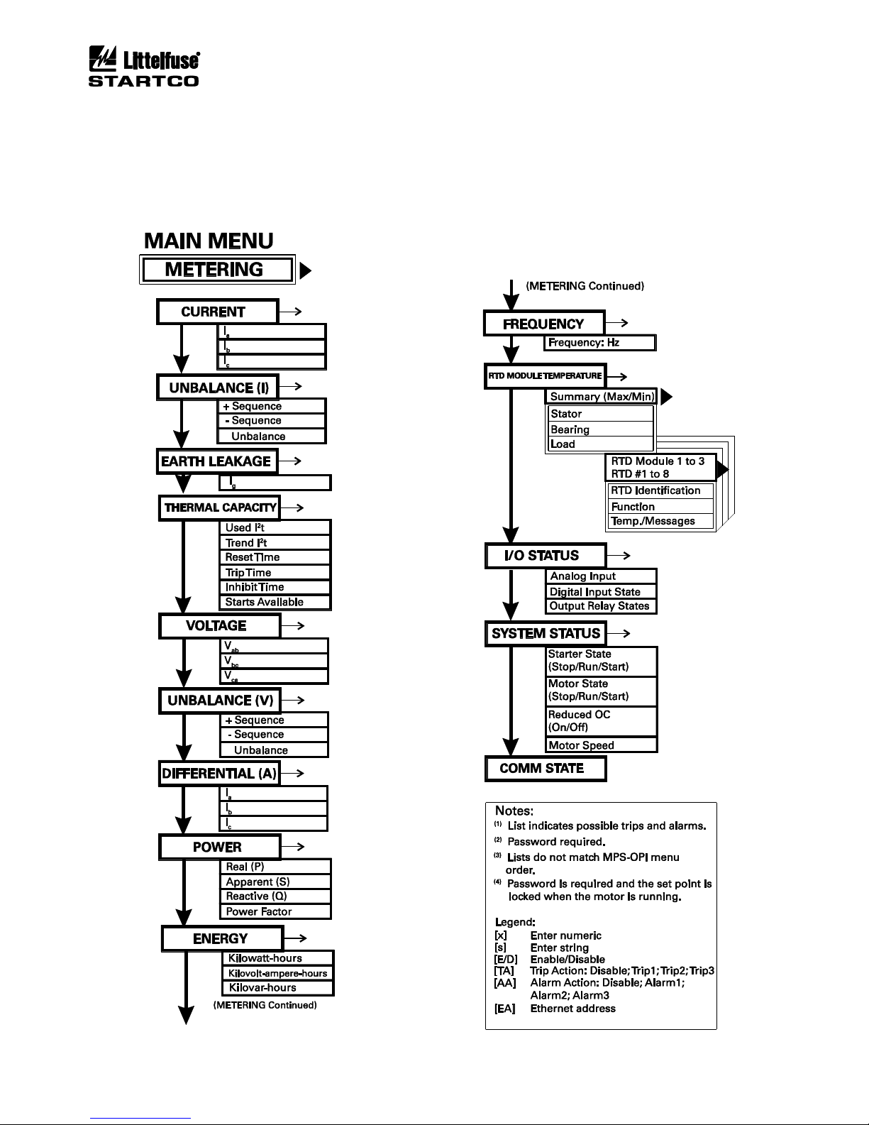
Page A-1
MPS Motor Protection System Rev. 6-F-022117
Appendix A, MPS-OPI Menu Map
APPENDIX A
MPS-OPI MENU MAP
Page 84
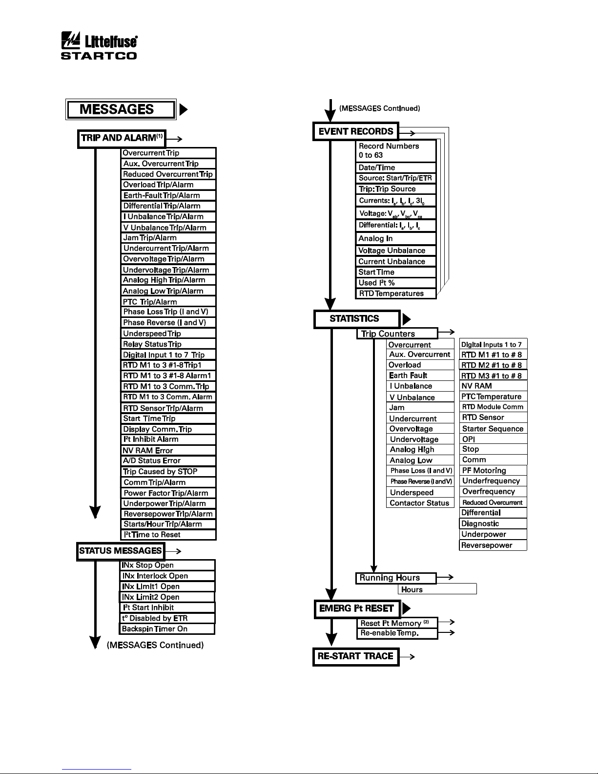
Page A-2
MPS Motor Protection System Rev. 6-F-022117
Appendix A, MPS-OPI Menu Map
Page 85
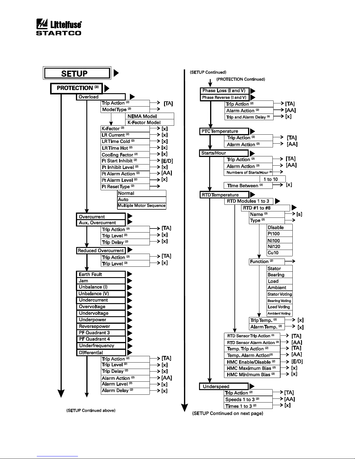
Page A-3
MPS Motor Protection System Rev. 6-F-022117
Appendix A, MPS-OPI Menu Map
Page 86
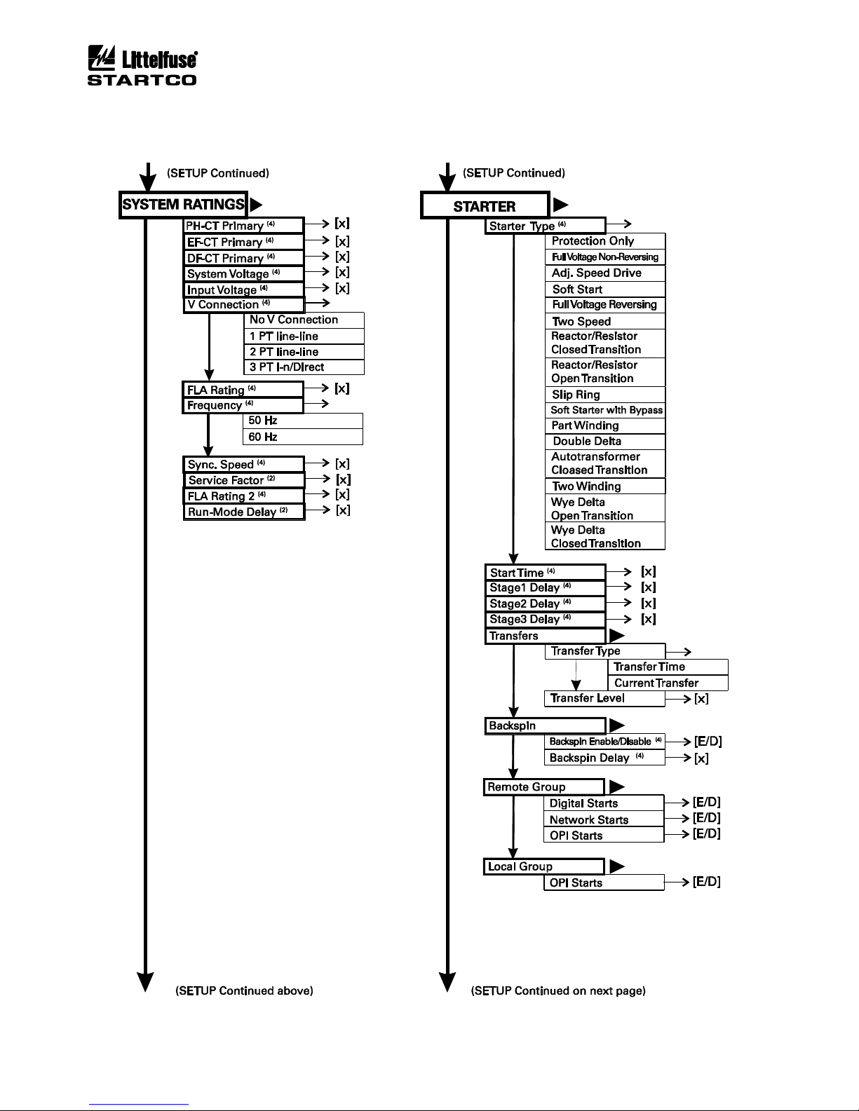
Page A-4
MPS Motor Protection System Rev. 6-F-022117
Appendix A, MPS-OPI Menu Map
Page 87
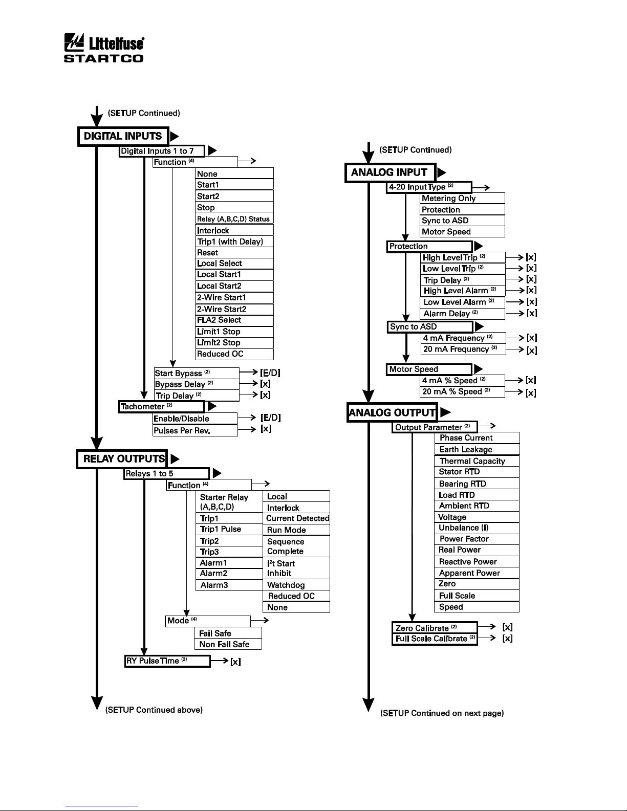
Page A-5
MPS Motor Protection System Rev. 6-F-022117
Appendix A, MPS-OPI Menu Map
Page 88
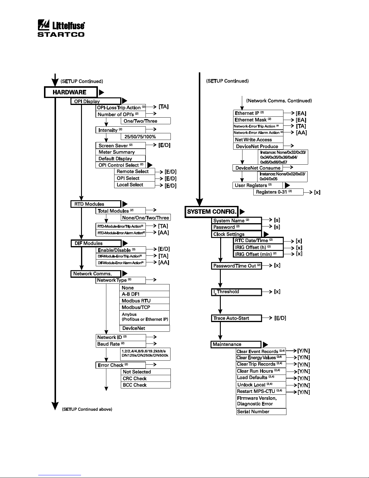
Page A-6
MPS Motor Protection System Rev. 6-F-022117
Appendix A, MPS-OPI Menu Map
Page 89

Page B-1
MPS Motor Protection System Rev. 6-F-022117
Appendix B, MPS Set-Up Record
APPENDIX B
MPS SET-UP RECORD
Motor: _____________________________ MPS S/N: __________________________ Date: _____________________
Firmware Revision:___________________________
PART I: SYSTEM AND MOTOR PARAMETERS
PARAMETER AND SETTINGS
MIN
DEFAULT
MAX
UNIT
PROGRAM SELECTION
System Ratings
PH-CT Primary (Ip)
1
100.00
5,000
A
EF-CT Primary (Ie)
1
5.00
5,000
A
DF-CT Primary (Id)
1
100.00
5,000
A
System Voltage
0.12
0.60
25
kV
Input Voltage
0.06
0.12
0.6
kV
Input Voltage Connection
None
q None
q 1PT
q 2PT
q 3PT/Direct
Full-Load Current
1
100.00
5,000
A
Frequency
60 Hz
q 50
q 60
Synchronous Speed
10
1,800.00
10k
rpm
Service Factor
1
1.00
1.25
pu
FLA Rating 2
1
100.00
5,000
A
Run-Mode Delay
5
10.00
120
s
Digital Inputs
See Table 4.2 Input Function Definition
Input 1: Function
Not Used
Start Bypass
Disable
q Enable
q Disable
Bypass Delay
0.5
5.00
100
s
Trip Delay
0.01
0.10
100
s
Input 2: Function
Not Used
Start Bypass
Disable
q Enable
q Disable
Bypass Delay
0.5
5.00
100
s
Trip Delay
0.01
0.10
100
s
Input 3: Function
Not Used
Start Bypass
Disable
q Enable
q Disable
Bypass Delay
0.5
5.00
100
s
Trip Delay
0.01
0.10
100
s
Input 4: Function
Not Used
Start Bypass
Disable
q Enable
q Disable
Bypass Delay
0.5
5.00
100
s
Trip Delay
0.01
0.10
100
s
Input 5: Function
Not Used
Start Bypass
Disable
q Enable
q Disable
Bypass Delay
0.5
5.00
100
s
Trip Delay
0.01
0.10
100
s
Input 6: Function
Not Used
Start Bypass
Disable
q Enable
q Disable
Bypass Delay
0.5
5.00
100
s
Trip Delay
0.01
0.10
100
s
Input 7: Function
Not Used
Start Bypass
Disable
q Enable
q Disable
Bypass Delay
0.5
5.00
100
s
Trip Delay
0.01
0.10
100
s
Page 90
Page B-2
MPS Motor Protection System Rev. 6-F-022117
Appendix B, MPS Set-Up Record
PARAMETER AND SETTINGS
MIN
DEFAULT
MAX
UNIT
PROGRAM SELECTION
Tachometer
Disable
q Enable
q Disable
Pulses per Revolution
1
60.00
100
Relay Outputs
See Table 4.1 Output Function Definition
Relay 1: Function
None
Mode
Fail-Safe
q Fail-Safe
q Non-Fail-Safe
Relay 2: Function
None
Mode
Fail-Safe
q Fail-Safe
q Non-Fail-Safe
Relay 3: Function
None
Mode
Fail-Safe
q Fail-Safe
q Non-Fail-Safe
Relay 4: Function
None
Mode
Fail-Safe
q Fail-Safe
q Non-Fail-Safe
Relay 5: Function
None
Mode
Fail-Safe
q Fail-Safe
q Non-Fail-Safe
RY Pulse Time
0.05
0.25
10 s
Analog Input
4-20 Input Type
Metering
Only
q Metering Only
q Protection
q Sync. to ASD
q Motor Speed
Protection:
High-Level Trip
0.1
16.00
20
mA
Low-Level Trip
0.1
7.00
20
mA
Trip Delay
0.01
5.00
100
s
High-Level Alarm
0.1
14.00
20
mA
Low-Level Alarm
0.1
9.00
20
mA
Alarm Delay
0.01
1.00
100
s
Sync to ASD Set Points:
4-mA Frequency
0
10.00
70
Hz
20-mA Frequency
0
60.00
70
Hz
Motor Speed Set Points:
4-mA Percent Speed
0
10.00
100
%
20-mA Percent Speed
0
100.00
100
%
Analog Output
Output Parameter
Phase
Current
See Table 4.3 Analog Output Parameter
Definition
Zero Calibrate
Factory Calibrated
Full-Scale Calibrate
Factory Calibrated
OPI Display
OPI-Loss Trip
Trip1
q Disable
q Trip2
q Trip1
q Trip3
Number of OPI’s
1
q 1
q 2
q 3
Intensity
100 %
q 25
q 50
q 75
q 100
Screen Saver
Enable
q Enable
q Disable
OPI Control Select
Remote Select
Enable
q Enable
q Disable
OPI Select
Enable
q Enable
q Disable
Local Select
Enable
q Enable
q Disable
RTD Modules
Total Modules
0
q 0
q 1
q 2
q 3
RTD-Module-Error Trip Action
Disable
q Disable
q Trip2
q Trip1
q Trip3
Page 91
Page B-3
MPS Motor Protection System Rev. 6-F-022117
Appendix B, MPS Set-Up Record
PARAMETER AND SETTINGS
MIN
DEFAULT
MAX
UNIT
PROGRAM SELECTION
RTD-Module-Error Alarm
Action
Disable
q Disable
q Alarm2
q Alarm1
q Alarm3
Temperature Trip Action
Trip1
q Disable
q Trip2
q Trip1
q Trip3
Temperature Alarm Action
Alarm1
q Disable
q Alarm2
q Alarm1
q Alarm3
DIF Module
Enable/Disable
Disable
q Enable
q Disable
DIF-Module-Error Trip Action
Disable
q Disable
q Trip2
q Trip1
q Trip3
DIF-Module-Error Alarm
Action
Disable
q Disable
q Trip2
q Trip1
q Trip3
Network Communications
Network Type
Modbus
q None
q Allen-Bradley
q Modbus
q DeviceNet
q Anybus
q Modbus TCP
Network ID
0
254
255
Baud Rate
SCI 9600
q SCI 1200
q SCI 2400
q SCI 4800
q SCI 9600
q SCI 19200
(1)
q DN125
q DN250
q DN500
Error Checking
Not
Selected
q Not Selected
q CRC
q BCC
Ethernet IP
192.168.
000.001
Ethernet Mask
255.255.
255.000
Default Gateway
0.0.0.0
Network-Error Trip Action
Disable
q Disable
q Trip2
q Trip1
q Trip3
Network-Error Alarm Action
Disable
q Disable
q Alarm2
q Alarm1
q Alarm3
DeviceNet Producing Assembly
0x36
q None
q 0x33
q 0x35
q 0x64
q 0x66
q 0x32
q 0x34
q 0x36
q 0x65
q 0x67
DeviceNet Consuming Assembly
None
q None
q 0x03
q 0x05
q 0x02
q 0x04
System Name
Startco MPS
Change Password
1111
Password Timeout
1
10.00
60
min.
Ip Threshold
(IP is Phase-CT-Primary Rating)
0.10
0.10
0.50
x Ip
Firmware Revision
See Protection | System Config | Maintenance | Firmware Version
Trace Auto-Start
Disable
q Enable
q Disable
(1)
Error rate is 1 byte/120 kB. For high reliability, use SCI9600.
Page 92
Page B-4
MPS Motor Protection System Rev. 6-F-022117
Appendix B, MPS Set-Up Record
PART II: STARTER PARAMETERS
SET POINT
MIN
DEFAULT
MAX
UNIT
PROGRAM SELECTION
Starter Type (see Table 6.2)
Protection Only
Start Time
0.1
20.00
500 s
Stage 1 Delay
0.1
20.00
500 s
Stage 2 Delay
0.1
20.00
500 s
Stage 3 Delay
0.1
20.00
500 s
Backspin Timer
Disable
q Enable
q Disable
Backspin Delay
0.1
5.00
3,600
s
Remote Group
Digital Inputs
Enable
q Enable
q Disable
Network
Enable
q Enable
q Disable
OPI
Enable
q Enable
q Disable
Transfer
Type
Time
q Time
q Current
Level
1.0
1.25
3.0
x FLA
PART III: PROTECTION SET POINTS
FUNCTION & SET POINT
MIN
DEFAULT
MAX
UNIT
PROGRAM SELECTION
Overload
Trip Action
Trip1
q Disable
q Trip2
q Trip1
q Trip3
Model Type
NEMA
q NEMA
q K-Factor
K-Factor
1
6.00
10 Locked-Rotor Current
1.5
6.00
10
x FLA
Locked-Rotor Time Cold
0.10
10.00
100
s
Locked-Rotor Time Hot
0.10
5.00
100
s
Cooling Factor
0.10
2.00
10 I2t Start Inhibit
Disable
q Enable
q Disable
I2t Inhibit Level
(Per Unit Based on 100% I2t)
0.10
0.30
.90
pu
I2t Alarm Action
Alarm1
q Disable
q Alarm2
q Alarm1
q Alarm3
I2t Overload Alarm Level
0.50
1.00 1 pu
Reset Type
Normal
q Normal
q Auto
q Multiple Motor Sequence
Overcurrent
Trip Action
Trip1
q Disable
q Trip2
q Trip1
q Trip3
Trip Level
(Ip is Phase-CT-Primary Rating)
1
10.00
15
x Ip
Trip Delay
0
0.05
10 s Auxiliary Overcurrent
Trip Action
Disable
q Disable
q Trip2
q Trip1
q Trip3
Trip Level
(Ip is Phase-CT-Primary Rating)
1
10.00
15
x Ip
Trip Delay
0
0.05
10 s
Page 93
Page B-5
MPS Motor Protection System Rev. 6-F-022117
Appendix B, MPS Set-Up Record
FUNCTION & SET POINT
MIN
DEFAULT
MAX
UNIT
PROGRAM SELECTION
Reduced Overcurrent
Trip Action
Trip1
q Disable
q Trip2
q Trip1
q Trip3
Trip Level
(Ip is Phase-CT-Primary Rating)
1
2.00
15
x Ip
Earth Fault
Trip Action
Trip1
q Disable
q Trip2
q Trip1
q Trip3
Trip Level
(Ie is EF-CT-Primary Rating)
0.05
0.40 1 x Ie
Trip Delay
0
0.25
100
s
Alarm Action
Alarm1
q Disable
q Alarm2
q Alarm1
q Alarm3
Alarm Level
(Ie is EF-CT-Primary Rating)
0.05
0.20 1 x Ie
Alarm Delay
0
1.00
100
s
Jam
Trip Action
Trip1
q Disable
q Trip2
q Trip1
q Trip3
Trip Level
1
6.00
10
x FLA
Trip Delay
1
5.00
100
s
Alarm Action
Alarm1
q Disable
q Alarm2
q Alarm1
q Alarm3
Alarm Level
1
3.00
10
x FLA
Alarm Delay
1
5.00
100
s
Unbalance (I)
Trip Action
Trip1
q Disable
q Trip2
q Trip1
q Trip3
Trip Level
(Per Unit Based on I2/I1)
0.05
0.25 1 pu
Trip Delay
1
15.00
100
s
Alarm Action
Alarm1
q Disable
q Alarm2
q Alarm1
q Alarm3
Alarm Level
0.05
0.10 1 pu
Alarm Delay
1
10.00
100
s
Phase Loss (I)
Trip Action
Trip1
q Disable
q Trip2
q Trip1
q Trip3
Phase Loss Delay
1
5.00
100
s
Phase Reverse (I)
Trip Action
Disable
q Disable
q Trip2
q Trip1
q Trip3
Alarm Action
Alarm1
q Disable
q Alarm2
q Alarm1
q Alarm3
Trip and Alarm Delay
1
2.00
100
s
Page 94
Page B-6
MPS Motor Protection System Rev. 6-F-022117
Appendix B, MPS Set-Up Record
FUNCTION & SET POINT
MIN
DEFAULT
MAX
UNIT
PROGRAM SELECTION
Unbalance (V)
Trip Action
Trip1
q Disable
q Trip2
q Trip1
q Trip3
Trip Level
(Per Unit Based on V2/V1)
0.05
0.10 1 pu
Trip Delay
1
15.00
100
s
Alarm Action
Alarm1
q Disable
q Alarm2
q Alarm1
q Alarm3
Alarm Level
0.05
0.05 1 pu
Alarm Delay
1
10.00
100
s
Phase Loss (V)
Trip Action
Disable
q Disable
q Trip2
q Trip1
q Trip3
Phase Loss Delay
1
5.00
100
s
Phase Reverse (V)
Trip Action
Disable
q Disable
q Trip2
q Trip1
q Trip3
Alarm Action
Alarm1
q Disable
q Alarm2
q Alarm1
q Alarm3
Phase Reverse
Trip and Alarm Delay
1
2.00
100
s
Undercurrent
Trip Action
Disable
q Disable
q Trip2
q Trip1
q Trip3
Trip Level
0.1
0.50
1
x FLA
Trip Delay
1
10.00
100
s
Alarm Action
Disable
q Disable
q Alarm2
q Alarm1
q Alarm3
Alarm Level
0.1
0.80
1
x FLA
Alarm Delay
1
20.00
100
s
Differential
Trip Action
Disable
q Disable
q Trip2
q Trip1
q Trip3
Trip Level
(Id is DF-CT-Primary Current)
0.1
1.00
15
x Id
Trip Delay
0
0.10
10
s
Alarm Action
Disable
q Disable
q Alarm2
q Alarm1
q Alarm3
Alarm Level
(Id is DF-CT-Primary Current)
0.1
0.50
15
x Id
Alarm Delay
0
0.10
10
s
PF Quadrant 4
Trip Action
Disable
q Disable
q Trip2
q Trip1
q Trip3
Trip Level
0.5
0.80 1
Trip Delay
0.1
5.00
500
s
Alarm Action
Disable
q Disable
q Alarm2
q Alarm1
q Alarm3
Alarm Level
0.5
0.90 1
Alarm Delay
0.1
5.00
500
s
Page 95
Page B-7
MPS Motor Protection System Rev. 6-F-022117
Appendix B, MPS Set-Up Record
FUNCTION & SET POINT
MIN
DEFAULT
MAX
UNIT
PROGRAM SELECTION
PF Quadrant 3
Trip Action
Disable
q Disable
q Trip2
q Trip1
q Trip3
Trip Level
0.5
0.80 1
Trip Delay
0.1
5.00
500
s
Alarm Action
Disable
q Disable
q Alarm2
q Alarm1
q Alarm3
Alarm Level
0.5
0.90 1
Alarm Delay
0.1
5.00
500
s
Underpower
Trip Action
Disable
q Disable
q Trip2
q Trip1
q Trip3
Trip Level
(Per Unit of Rated Power)
0.1
0.80 1 pu
Trip Delay
0.5
5.00
500
s
Alarm Action
Disable
q Disable
q Alarm2
q Alarm1
q Alarm3
Alarm Level
(Per Unit of Rated Power)
0.1
0.80 1 pu
Alarm Delay
0.5
1.00
500
s
Reversepower
Trip Action
Disable
q Disable
q Trip2
q Trip1
q Trip3
Trip Level
(Per Unit of Rated Power)
0.1
0.20 1 pu
Trip Delay
0.5
5.00
500
s
Alarm Action
Disable
q Disable
q Alarm2
q Alarm1
q Alarm3
Alarm Level
(Per Unit of Rated Power)
0.1
0.20 1 pu
Alarm Delay
0.5
1.00
500
s
Underfrequency
Trip Action
Disable
q Disable
q Trip2
q Trip1
q Trip3
Trip Level
30
45
80
Hz
Trip Delay
0.5 5 500
s
Alarm Action
Disable
q Disable
q Alarm2
q Alarm1
q Alarm3
Alarm Level
30
48
80
Hz
Alarm Delay
0.5 1 500
s
Overfrequency
Trip Action
Disable
q Disable
q Trip2
q Trip1
q Trip3
Trip Level
30
65
80
Hz
Trip Delay
0.5 5 500
s
Alarm Action
Disable
q Disable
q Alarm2
q Alarm1
q Alarm3
Alarm Level
30
62
80
Hz
Alarm Delay
0.5 1 500
s
Page 96
Page B-8
MPS Motor Protection System Rev. 6-F-022117
Appendix B, MPS Set-Up Record
FUNCTION & SET POINT
MIN
DEFAULT
MAX
UNIT
PROGRAM SELECTION
PTC Temperature
Trip Action
Disable
q Disable
q Trip2
q Trip1
q Trip3
Alarm Action
Disable
q Disable
q Alarm2
q Alarm1
q Alarm3
RTD-Sensor-Error Trip Action
Disable
q Disable
q Trip2
q Trip1
q Trip3
RTD-Sensor-Error Alarm
Action
Alarm1
q Disable
q Alarm2
q Alarm1
q Alarm3
Hot-Motor Compensation (HMC)
Disable
q Enable
q Disable
HMC High
40
150.00
200
°C
HMC Low
40
40.00
200
°C
Acceleration Failure—
Underspeed
Trip Action
Disable
q Disable
q Trip2
q Trip1
q Trip3
Speed 1 (Percent Sync Speed)
1
30.00
100
% SS
Time 1
1
5.00
1,000
s
Speed 2
1
60.00
100
% SS
Time 2
1
10.00
1,000
s
Speed 3
1
90.00
100
% SS
Time 3
1
15.00
1,000
s
Overvoltage
Trip Action
Trip1
q Disable
q Trip2
q Trip1
q Trip3
Trip Level
(Vp is system voltage)
1
1.20
1.4
x Vp
Trip Delay
1
5.00
500
s
Alarm Action
Alarm1
q Disable
q Alarm2
q Alarm1
q Alarm3
Alarm Level
(Vp is system voltage)
1
1.10
1.4
x Vp
Alarm Delay
1
5.00
500
s
Undervoltage
Trip Action
Disable
q Disable
q Trip2
q Trip1
q Trip3
Trip Level
(Vp is system voltage)
0.5
0.70 1 x Vp
Trip Delay
1
5.00
500
s
Alarm Action
Disable
q Disable
q Alarm2
q Alarm1
q Alarm3
Alarm Level
(Vp is system voltage)
0.5
0.80 1 x Vp
Alarm Delay
1
5.00
500
s
Starts/Hour
Trip Action
Disable
q Disable
q Trip2
q Trip1
q Trip3
Alarm Action
q Disable
q Alarm2
q Alarm1
q Alarm3
Number of Starts/Hour
1 5 10
Time Between Starts
0
0.00
500
min
Page 97
Page B-9
MPS Motor Protection System Rev. 6-F-022117
Appendix B, MPS Set-Up Record
FUNCTION & SET POINT
MIN
DEFAULT
MAX
UNIT
PROGRAM SELECTION
RTD TEMPERATURE
Requires RTD Module(s)
RTD M1 #1:
Name
RTD Module 1 #1
Type
Disable
q Disable
q Pt100 Ω
q Ni100 Ω
q Ni120 Ω
q Cu10 Ω
Function
Stator
q Stator
q Bearing
q Stator Voting
q Bearing Voting
q Load
q Ambient
q Load Voting
q Ambient Voting
Trip
40
130.00
200
°C
Alarm
40
110.00
200
°C
RTD M1 #2:
Name
RTD Module 1 #2
Type
Disable
q Disable
q Pt100 Ω
q Ni100 Ω
q Ni120 Ω
q Cu10 Ω
Function
Stator
q Stator
q Bearing
q Stator Voting
q Bearing Voting
q Load
q Ambient
q Load Voting
q Ambient Voting
Trip
40
130.00
200
°C
Alarm
40
110.00
200
°C
RTD M1 #3:
Name
RTD Module 1 #3
Type
Disable
q Disable
q Pt100 Ω
q Ni100 Ω
q Ni120 Ω
q Cu10 Ω
Function
Stator
q Stator
q Bearing
q Stator Voting
q Bearing Voting
q Load
q Ambient
q Load Voting
q Ambient Voting
Trip
40
130.00
200
°C
Alarm
40
110.00
200
°C
RTD M1 #4:
Name
RTD Module 1 #4
Type
Disable
q Disable
q Pt100 Ω
q Ni100 Ω
q Ni120 Ω
q Cu10 Ω
Function
Stator
q Stator
q Bearing
q Stator Voting
q Bearing Voting
q Load
q Ambient
q Load Voting
q Ambient Voting
Trip
40
130.00
200
°C
Alarm
40
110.00
200
°C
Page 98
Page B-10
MPS Motor Protection System Rev. 6-F-022117
Appendix B, MPS Set-Up Record
FUNCTION & SET POINT
MIN
DEFAULT
MAX
UNIT
PROGRAM SELECTION
RTD M1 #5:
Name
RTD Module 1 #5
Type
Disable
q Disable
q Pt100 Ω
q Ni100 Ω
q Ni120 Ω
q Cu10 Ω
Function
Stator
q Stator
q Bearing
q Stator Voting
q Bearing Voting
q Load
q Ambient
q Load Voting
q Ambient Voting
Trip
40
130.00
200
°C
Alarm
40
110.00
200
°C
RTD M1 #6:
Name
RTD Module 1 #6
Type
Disable
q Disable
q Pt100 Ω
q Ni100 Ω
q Ni120 Ω
q Cu10 Ω
Function
Stator
q Stator
q Bearing
q Stator Voting
q Bearing Voting
q Load
q Ambient
q Load Voting
q Ambient Voting
Trip
40
130.00
200
°C
Alarm
40
110.00
200
°C
RTD M1 #7:
Name
RTD Module 1 #7
Type
Disable
q Disable
q Pt100 Ω
q Ni100 Ω
q Ni120 Ω
q Cu10 Ω
Function
Stator
q Stator
q Bearing
q Stator Voting
q Bearing Voting
q Load
q Ambient
q Load Voting
q Ambient Voting
Trip
40
130.00
200
°C
Alarm
40
110.00
200
°C
RTD M1 #8:
Name
RTD Module 1 #8
Type
Disable
q Disable
q Pt100 Ω
q Ni100 Ω
q Ni120 Ω
q Cu10 Ω
Function
Stator
q Stator
q Bearing
q Stator Voting
q Bearing Voting
q Load
q Ambient
q Load Voting
q Ambient Voting
Trip
40
130.00
200
°C
Alarm
40
110.00
200
°C
Page 99
Page B-11
MPS Motor Protection System Rev. 6-F-022117
Appendix B, MPS Set-Up Record
FUNCTION & SET POINT
MIN
DEFAULT
MAX
UNIT
PROGRAM SELECTION
RTD M2 #1:
Name
RTD Module 2 #1
Type
Disable
q Disable
q Pt100 Ω
q Ni100 Ω
q Ni120 Ω
q Cu10 Ω
Function
Stator
q Stator
q Bearing
q Stator Voting
q Bearing Voting
q Load
q Ambient
q Load Voting
q Ambient Voting
Trip
40
130.00
200
°C
Alarm
40
110.00
200
°C
RTD M2 #2:
Name
RTD Module 2 #2
Type
Disable
q Disable
q Pt100 Ω
q Ni100 Ω
q Ni120 Ω
q Cu10 Ω
Function
Stator
q Stator
q Bearing
q Stator Voting
q Bearing Voting
q Load
q Ambient
q Load Voting
q Ambient Voting
Trip
40
130.00
200
°C
Alarm
40
110.00
200
°C
RTD M2 #3:
Name
RTD Module 2 #3
Type
Disable
q Disable
q Pt100 Ω
q Ni100 Ω
q Ni120 Ω
q Cu10 Ω
Function
Stator
q Stator
q Bearing
q Stator Voting
q Bearing Voting
q Load
q Ambient
q Load Voting
q Ambient Voting
Trip
40
130.00
200
°C
Alarm
40
110.00
200
°C
RTD M2 #4:
Name
RTD Module 2 #4
Type
Disable
q Disable
q Pt100 Ω
q Ni100 Ω
q Ni120 Ω
q Cu10 Ω
Function
Stator
q Stator
q Bearing
q Stator Voting
q Bearing Voting
q Load
q Ambient
q Load Voting
q Ambient Voting
Trip
40
130.00
200
°C
Alarm
40
110.00
200
°C
Page 100
Page B-12
MPS Motor Protection System Rev. 6-F-022117
Appendix B, MPS Set-Up Record
FUNCTION & SET POINT
MIN
DEFAULT
MAX
UNIT
PROGRAM SELECTION
RTD M2 #5:
Name
RTD Module 2 #5
Type
Disable
q Disable
q Pt100 Ω
q Ni100 Ω
q Ni120 Ω
q Cu10 Ω
Function
Stator
q Stator
q Bearing
q Stator Voting
q Bearing Voting
q Load
q Ambient
q Load Voting
q Ambient Voting
Trip
40
130.00
200
°C
Alarm
40
110.00
200
°C
RTD M2 #6:
Name
RTD Module 2 #6
Type
Disable
q Disable
q Pt100 Ω
q Ni100 Ω
q Ni120 Ω
q Cu10 Ω
Function
Stator
q Stator
q Bearing
q Stator Voting
q Bearing Voting
q Load
q Ambient
q Load Voting
q Ambient Voting
Trip
40
130.00
200
°C
Alarm
40
110.00
200
°C
RTD M2 #7:
Name
RTD Module 2 #7
Type
Disable
q Disable
q Pt100 Ω
q Ni100 Ω
q Ni120 Ω
q Cu10 Ω
Function
Stator
q Stator
q Bearing
q Stator Voting
q Bearing Voting
q Load
q Ambient
q Load Voting
q Ambient Voting
Trip
40
130.00
200
°C
Alarm
40
110.00
200
°C
RTD M2 #8:
Name
RTD Module 2 #8
Type
Disable
q Disable
q Pt100 Ω
q Ni100 Ω
q Ni120 Ω
q Cu10 Ω
Function
Stator
q Stator
q Bearing
q Stator Voting
q Bearing Voting
q Load
q Ambient
q Load Voting
q Ambient Voting
Trip
40
130.00
200
°C
Alarm
40
110.00
200
°C
 Loading...