

Page 1
6-PIN DIP RANDOM-PHASE
OPTOISOLATORS TRIAC DRIVER OUTPUT
(250/400 VOLT PEAK)
MOC3010M MOC3011M MOC3012M MOC3020M MOC3021M MOC3022M MOC3023M
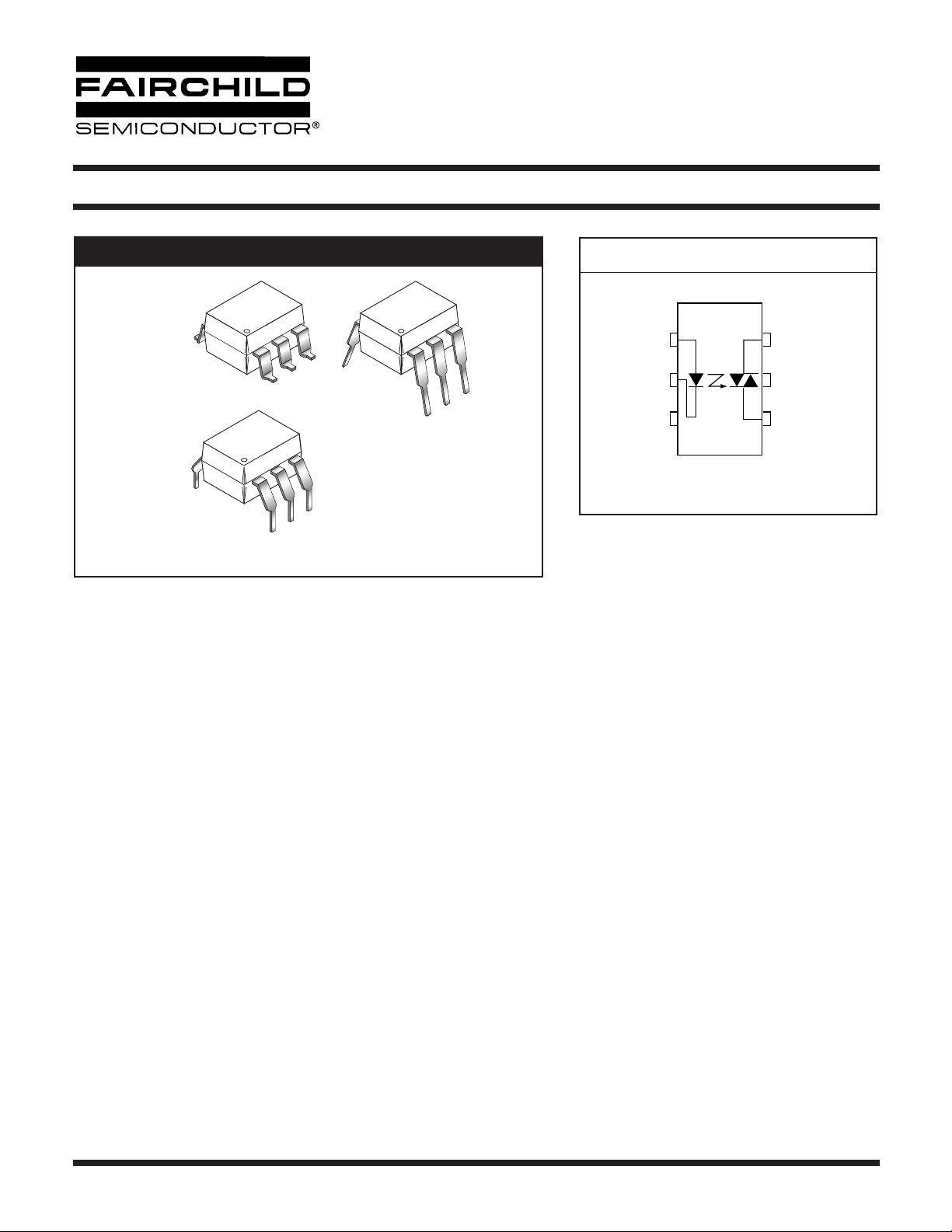
PACKAGE
SCHEMATIC
1
ANODE
MAIN TERM.
6
6
6
CATHODE
2
NC*
5
1
3
1
N/C
*DO NOT CONNECT
(TRIAC SUBSTRATE)
4
MAIN TERM.
6
1
DESCRIPTION
The MOC301XM and MOC302XM series are optically isolated triac driver devices. These devices contain a GaAs infrared
emitting diode and a light activated silicon bilateral switch, which functions like a triac. They are designed for interfacing between
electronic controls and power triacs to control resistive and inductive loads for 115 VAC operations.
FEATURES
• Excellent I
• High isolation voltage—minimum 5300 VAC RMS
• Underwriters Laboratory (UL) recognized—File #E90700
•Peak blocking voltage
– 250V-MOC301XM
– 400V-MOC302XM
• VDE recognized (File #94766)
– Ordering option V (e.g. MOC3023VM)
stability—IR emitting diode has low degradation
FT
APPLICATIONS
• Industrial controls • Solenoid/valve controls
•Traffic lights • Static AC power switch
•Vending machines • Incandescent lamp dimmers
• Solid state relay • Motor control
• Lamp ballasts
© 2005 Fairchild Semiconductor Corporation
Page 1 of 10
6/15/05
Page 2

6-PIN DIP RANDOM-PHASE
OPTOISOLATORS TRIAC DRIVER OUTPUT
(250/400 VOLT PEAK)
MOC3010M MOC3011M MOC3012M MOC3020M MOC3021M MOC3022M MOC3023M
ABSOLUTE MAXIMUM RATINGS
(T
= 25°C unless otherwise noted)
A
Parameters Symbol Device Value Units
TOTAL DEVICE
Storage Temperature T
Operating Temperature T
Lead Solder Temperature T
Junction Temperature Range T
(1)
Isolation Surge Voltage
(peak AC voltage, 60Hz, 1 sec duration)
Total Device Power Dissipation @ 25°C
Derate above 25°C 4.4 mW/°C
V
STG
OPR
SOL
J
ISO
P
D
All -40 to +150 °C
All -40 to +85 °C
All 260 for 10 sec °C
All -40 to +100 °C
All 7500 Vac(pk)
All
330 mW
EMITTER
Continuous Forward Current I
Reverse Voltage V
Total Power Dissipation 25°C Ambient
Derate above 25°C 1.33 mW/°C
F
R
P
D
All 60 mA
All 3 V
All
100 mW
DETECTOR
Off-State Output Terminal Voltage V
Peak Repetitive Surge Current (PW = 1 ms, 120 pps) I
Total Power Dissipation @ 25°C Ambient
Derate above 25°C 4 mW/°C
DRM
TSM
P
D
MOC3010M/1M/2M
MOC3020M/1M/2M/3M
All 1 A
All
250
400
V
300 mW
Note
1. Isolation surge voltage, V
, is an internal device dielectric breakdown rating. For this test, Pins 1 and 2 are common, and
ISO
Pins 4, 5 and 6 are common.
© 2005 Fairchild Semiconductor Corporation
Page 2 of 10
6/15/05
Page 3

6-PIN DIP RANDOM-PHASE
OPTOISOLATORS TRIAC DRIVER OUTPUT
(250/400 VOLT PEAK)
MOC3010M MOC3011M MOC3012M MOC3020M MOC3021M MOC3022M MOC3023M
ELECTRICAL CHARACTERISTICS
INDIVIDUAL COMPONENT CHARACTERISTICS
Parameters Test Conditions Symbol Device Min Typ Max Units
EMITTER
Input Forward Voltage I
Reverse Leakage Current V
DETECTOR
Peak Blocking Current,Either Direction Rated V
Peak On-State Voltage,Either Direction I
(T
= 25°C Unless otherwise specified)
A
= 10 mA V
F
= 3 V, T
R
= 100 mA peak, I
TM
= 25°C I
A
, I
= 0 (note 1) I
DRM
F
= 0 V
F
F
R
DRM
TM
All 1.15 1.5 V
All 0.01 100 µA
All 10 100 nA
All 1.8 3 V
TRANSFER CHARACTERISTICS
(T
= 25°C Unless otherwise specified.)
A
DC Characteristics Test Conditions Symbol Device Min Typ Max Units
MOC3020M 30
LED Trigger Current Voltage = 3V (note 3) I
Holding Current, Either Direction I
FT
MOC3010M
MOC3021M
MOC3011M
MOC3022M
MOC3012M
MOC3023M
H
All 100 µA
15
10
mA
5
Note
1. Test voltage must be applied within dv/dt rating.
2. This is static dv/dt. See Figure 5 for test circuit. Commutating dv/dt is a function of the load-driving thyristor(s) only.
3. All devices are guaranteed to trigger at an I
between max I
(30 mA for MOC3020M, 15 mA for MOC3010M and MOC3021M, 10 mA for MOC3011M and MOC3022M,
FT
5 mA for MOC3012M and MOC3023M) and absolute max I
value less than or equal to max I
F
(60 mA).
F
. Therefore, recommended operating I
FT
lies
F
© 2005 Fairchild Semiconductor Corporation
Page 3 of 10
6/15/05
Page 4
6-PIN DIP RANDOM-PHASE
OPTOISOLATORS TRIAC DRIVER OUTPUT
(250/400 VOLT PEAK)
MOC3010M MOC3011M MOC3012M MOC3020M MOC3021M MOC3022M MOC3023M
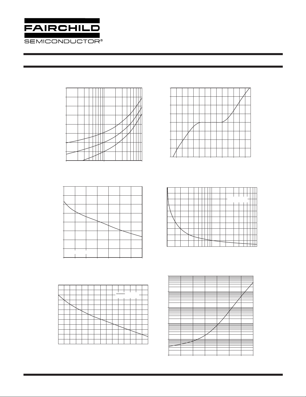
Fig. 1 LED Forward Voltage vs. Forward Current
1.8
1.7
1.6
1.5
1.4
1.3
- FORWARD VOLTAGE (V)
F
V
1.2
1.1
1.0
110100
IF - LED FORWARD CURRENT (mA)
TA = -55oC
T
= 25oC
A
T
= 100oC
A
Fig. 3 Trigger Current vs. Ambient Temperature
1.4
1.3
1.2
1.1
(NORMALIZED)
FT
1.0
0.9
0.8
TRIGGER CURRENT - I
0.7
NORMALIZED TO TA = 25∞C
0.6
-40 -20 0 20 40 60 80 100
AMBIENT TEMPERATURE - TA (oC)
Fig. 5 dv/dt vs. Temperature
12
10
8
µs)
6
STATIC dv/dt
CIRCUIT IN FIGURE 5
800
600
400
(mA)
TM
200
0
-200
-400
ON-STATE CURRENT - I
-600
-800
-3 -2 -1 0 1 2 3
ON-STATE VOLTAGE - VTM (V)
Fig. 4 LED Current Required to Trigger vs. LED Pulse Width
25
Fig. 2 On-State Characteristics
20
15
(NORMALIZED)
FT
10
5
TRIGGER CURRENT - I
0
12 5102050100
LED TRIGGER WIDTH - PWin (µs)
Fig. 6 Leakage Current, I
10000
1000
100
NORMALIZED TO:
PWin ≥ 100 µs
vs. Temperature
DRM
4
STATIC - dv/dt (V/
2
0
25 30 40 6050 70 80 90 100
Ambient Temperature - TA (oC)
© 2005 Fairchild Semiconductor Corporation
, LEAKAGE CURRENT (nA)
DRM
I
Page 4 of 10
10
1
0.1
-40 -20 0 20 40 60 80 100
TA, AMBIENT TEMPERATURE (oC)
6/15/05
Page 5
6-PIN DIP RANDOM-PHASE
OPTOISOLATORS TRIAC DRIVER OUTPUT
(250/400 VOLT PEAK)
MOC3010M MOC3011M MOC3012M MOC3020M MOC3021M MOC3022M MOC3023M
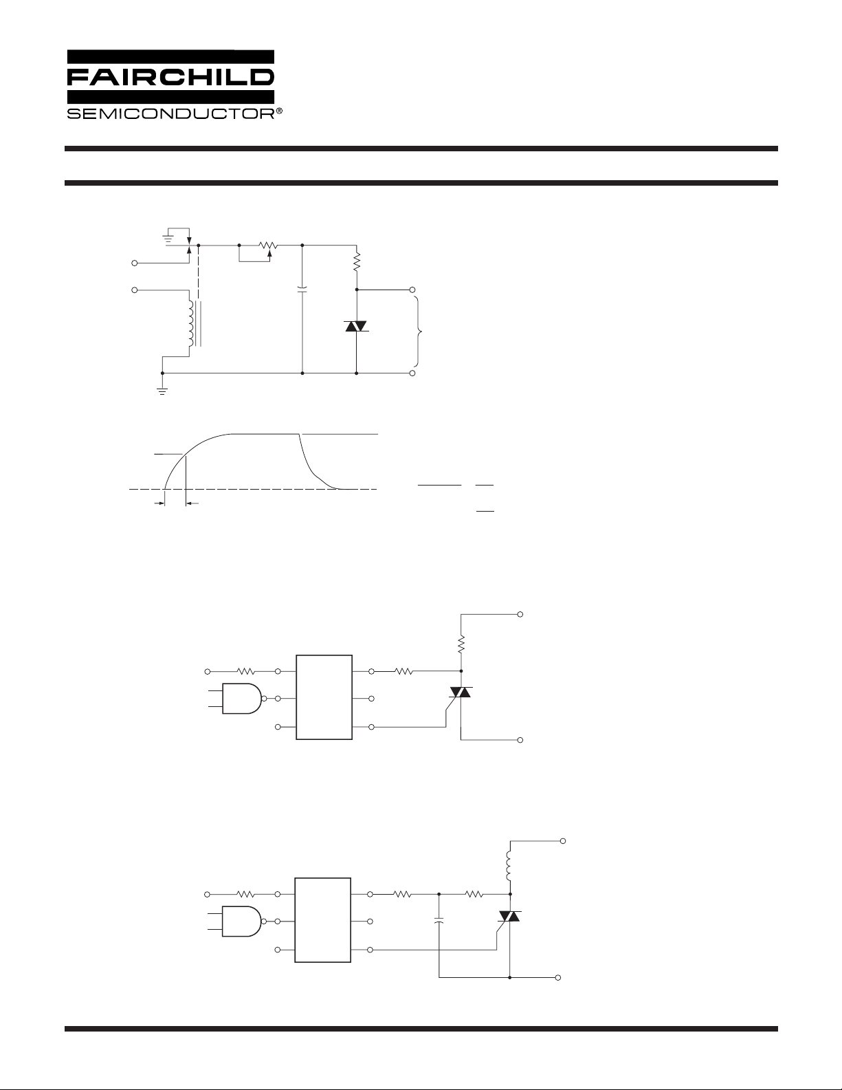
1. The mercury wetted relay provides a high speed repeated
400V (MOC302X)
250V (MOC301X)
Vdc
PULSE
INPUT
MERCURY
WETTED
RELAY
R
TEST
C
TEST
D.U. T.D.U. T.
R = 10 kΩ
X100
SCOPE
PROBE
pulse to the D.U.T.
2. 100x scope probes are used, to allow high speeds and
voltages.
3. The worst-case condition for static dv/dt is established by
triggering the D.U.T. with a normal LED input current, then
removing the current. The variable R
allows the dv/dt
TEST
to be gradually increased until the D.U.T. continues to
trigger in response to the applied voltage pulse, even
after the LED current has been removed. The dv/dt is
then decreased until the D.U.T. stops triggering. τ
RC
is
measured at this point and recorded.
V
=
400 V (MOC302X)
APPLIED VOLTAGE
WAVEFORM
0 VOLTS
252 V (MOC302X)
158 V (MOC301X)
τ
RC
max
= 250 V (MOC301X)
0.63 V
dv/dt =
Figure 5. Static dv/dt Test Circuit
Note: This optoisolator should not be used to drive a load directly.
It is intended to be a trigger device only.
R
in
V
CC
1
MOC3010M
2
MOC3011M
MOC3012M
3
Figure 6. Resistive Load
180
6
5
4
252
max
=
=
τ
158
τ
RC
RC
(MOC302X)
(MOC301X)
120 V
60 Hz
τ
RC
R
L
R
V
CC
in
Figure 7. Inductive Load with Sensitive Gate Triac (IGT ≤ 15 mA)
© 2005 Fairchild Semiconductor Corporation
1
2
3
MOC3010M
MOC3011M
MOC3012M
180
6
5
4
Page 5 of 10
0.1 µF
Z
L
2.4k
120 V
C1
60 Hz
6/15/05
Page 6
6-PIN DIP RANDOM-PHASE
OPTOISOLATORS TRIAC DRIVER OUTPUT
(250/400 VOLT PEAK)
MOC3010M MOC3011M MOC3012M MOC3020M MOC3021M MOC3022M MOC3023M
Z
L
R
in
V
CC
1
2
3
MOC3010M
MOC3011M
MOC3012M
180
6
5
4
0.2 µF
1.2 k
120 V
60 Hz
C1
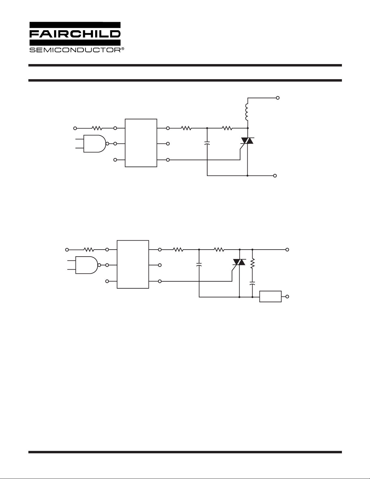
Figure 8. Inductive Load with Sensitive Gate Triac (IGT ≤ 15 mA)
R
in
V
CC
1
2
3
MOC3020M
MOC3021M
MOC3022M
MOC3023M
360
6
5
4
0.05 µF
470
39
0.01 µF
LOAD
HOT
240
VAC
GROUND
In this circuit the “hot” side of the line is switched and the load connected to the cold or ground side.
The 39 ohm resistor and 0.01µF capacitor are for snubbing of the triac, and the 470 ohm resistor and
0.05 µF capacitor are for snubbing the coupler. These components may or may not be necessary
depending upon the particular and load used.
© 2005 Fairchild Semiconductor Corporation
Figure 9. Typical Application Circuit
Page 6 of 10
6/15/05
Page 7
)
)
)
)
)
)
6-PIN DIP RANDOM-PHASE
OPTOISOLATORS TRIAC DRIVER OUTPUT
(250/400 VOLT PEAK)
MOC3010M MOC3011M MOC3012M MOC3020M MOC3021M MOC3022M MOC3023M
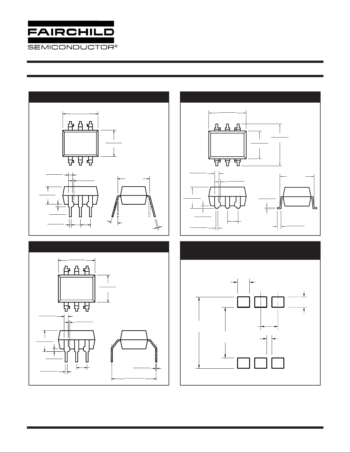
Package Dimensions (Through Hole) Package Dimensions (Surface Mount)
0.350 (8.89)
0.320 (8.13)
0.014 (0.36)
0.010 (0.25)
0.260 (6.60)
0.240 (6.10)
0.100 [2.54]
0.390 (9.90)
0.332 (8.43)
0.012 (0.30)
0.008 (0.20)
0.320 (8.13)
0.035 (0.88)
0.012 (0.30)
0.070 (1.77)
0.040 (1.02)
0.200 (5.08)
0.115 (2.93)
0.100 (2.54)
0.015 (0.38)
0.020 (0.50)
0.016 (0.41)
0.350 (8.89)
0.320 (8.13)
0.014 (0.36)
0.010 (0.25)
0.100 (2.54)
0.260 (6.60)
0.240 (6.10)
0.320 (8.13)
15°
0.012 (0.30)
0.070 (1.77)
0.040 (1.02)
0.200 (5.08)
0.115 (2.93)
0.025 (0.63)
0.020 (0.51)
0.020 (0.50)
0.016 (0.41)
Package Dimensions (0.4” Lead Spacing) Recommended Pad Layout for
0.350 (8.89)
0.320 (8.13)
Surface Mount Leadform
0.260 (6.60)
0.240 (6.10)
0.070 (1.77)
0.040 (1.02)
0.200 (5.08)
0.115 (2.93)
0.100 (2.54)
0.015 (0.38)
0.020 (0.50)
0.016 (0.41)
0.014 (0.36)
0.010 (0.25)
0.100 [2.54]
NOTE
All dimensions are in inches (millimeters)
© 2005 Fairchild Semiconductor Corporation
0.012 (0.30)
0.008 (0.21)
0.425 (10.80)
0.400 (10.16)
Page 7 of 10
0.425 (10.79
0.100 (2.54
0.305 (7.75
0.070 (1.78
0.060 (1.52
0.030 (0.76
6/15/05
Page 8
6-PIN DIP RANDOM-PHASE
OPTOISOLATORS TRIAC DRIVER OUTPUT
(250/400 VOLT PEAK)
MOC3010M MOC3011M MOC3012M MOC3020M MOC3021M MOC3022M MOC3023M
ORDERING INFORMATION
Option Order Entry Identifier Description
SS Surface Mount Lead Bend
SR2 SR2 Surface Mount; Tape and reel
TT 0.4" Lead Spacing
VV VDE 0884
TV TV VDE 0884, 0.4" Lead Spacing
SV SV VDE 0884, Surface Mount
SR2V SR2V VDE 0884, Surface Mount, Tape & Reel
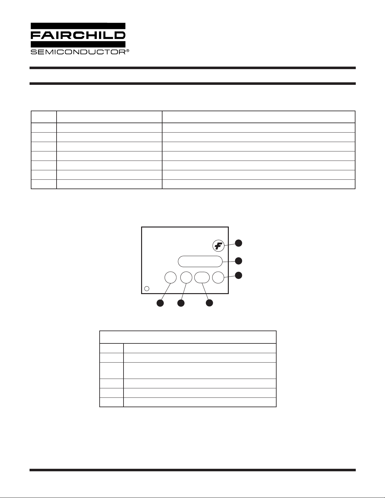
MARKING INFORMATION
Definitions
1Fairchild logo
2Device number
3
4 One digit year code, e.g., ‘3’
5Two digit work week ranging from ‘01’ to ‘53’
6 Assembly package code
*Note – Parts that do not have the ‘V’ option (see definition 3 above) that are marked with
date code ‘325’ or earlier are marked in portrait format.
1
MOC3010
V X YY Q
43
VDE mark (Note: Only appears on parts ordered with VDE
option – See order entry table)
5
2
6
© 2005 Fairchild Semiconductor Corporation
Page 8 of 10
6/15/05
Page 9
6-PIN DIP RANDOM-PHASE
OPTOISOLATORS TRIAC DRIVER OUTPUT
(250/400 VOLT PEAK)
MOC3010M MOC3011M MOC3012M MOC3020M MOC3021M MOC3022M MOC3023M
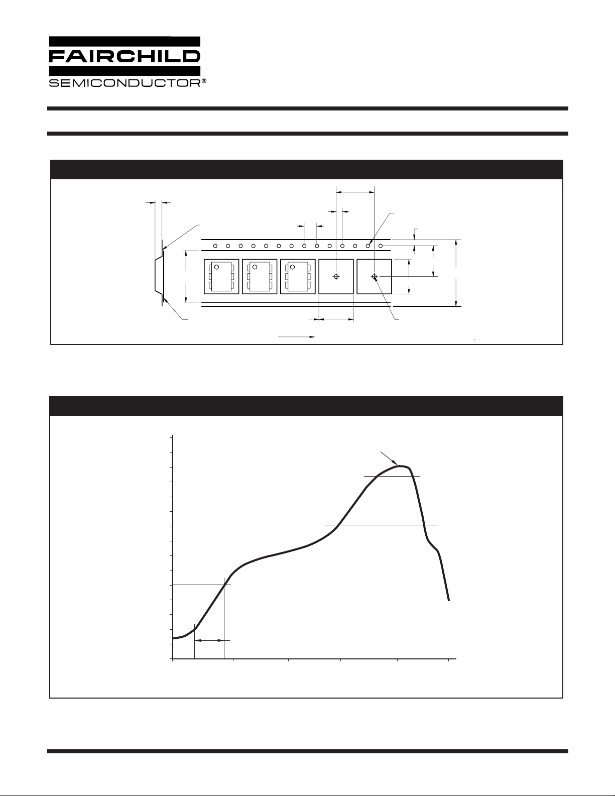
Carrier Tape Specifications
12.0 ± 0.1
4.5 ± 0.20
0.30 ± 0.05
21.0 ± 0.1
4.0 ± 0.1
2.0 ± 0.05
1.5 MIN
Ø
9.1 ± 0.20
1.75 ± 0.10
11.5 ± 1.0
24.0 ± 0.3
0.1 MAX
User Direction of Feed
NOTE
All dimensions are in inches (millimeters)
Reflow Profile (White Package, -M Suffix)
300
280
260
240
220
200
180
160
°C
140
120
100
80
60
40
20
0
0 60 180120 270
10.1 ± 0.20
1.822°C/Sec Ramp up rate
33 Sec
Time (s)
260°C
Time above
183°C = 90 Sec
Ø
1.5 ± 0.1/-0
>245°C = 42 Sec
360
© 2005 Fairchild Semiconductor Corporation
Page 9 of 10
6/15/05
Page 10

6-PIN DIP RANDOM-PHASE
OPTOISOLATORS TRIAC DRIVER OUTPUT
(250/400 VOLT PEAK)
MOC3010M MOC3011M MOC3012M MOC3020M MOC3021M MOC3022M MOC3023M
DISCLAIMER
FAIRCHILD SEMICONDUCTOR RESERVES THE RIGHT TO MAKE CHANGES WITHOUT FURTHER NOTICE TO
ANY PRODUCTS HEREIN TO IMPROVE RELIABILITY, FUNCTION OR DESIGN. FAIRCHILD DOES NOT ASSUME
ANY LIABILITY ARISING OUT OF THE APPLICATION OR USE OF ANY PRODUCT OR CIRCUIT DESCRIBED HEREIN;
NEITHER DOES IT CONVEY ANY LICENSE UNDER ITS PATENT RIGHTS, NOR THE RIGHTS OF OTHERS.
LIFE SUPPORT POLICY
FAIRCHILD’S PRODUCTS ARE NOT AUTHORIZED FOR USE AS CRITICAL COMPONENTS IN LIFE SUPPORT DEVICES
OR SYSTEMS WITHOUT THE EXPRESS WRITTEN APPROVAL OF THE PRESIDENT OF FAIRCHILD SEMICONDUCTOR
CORPORATION. As used herein:
1. Life support devices or systems are devices or systems
which, (a) are intended for surgical implant into the body, or
(b) support or sustain life, and (c) whose failure to perform
when properly used in accordance with instructions for use
provided in the labeling, can be reasonably expected to
result in a significant injury of the user.
2. A critical component in any component of a life support
device or system whose failure to perform can be
reasonably expected to cause the failure of the life support
device or system, or to affect its safety or effectiveness.
© 2005 Fairchild Semiconductor Corporation
Page 10 of 10
6/15/05
 Loading...