

Datasheet MMBZ5258BW, MMBZ5256BW, MMBZ5255BW, MMBZ5252BW, MMBZ5243BW Datasheet (PANJIT)
...Page 1
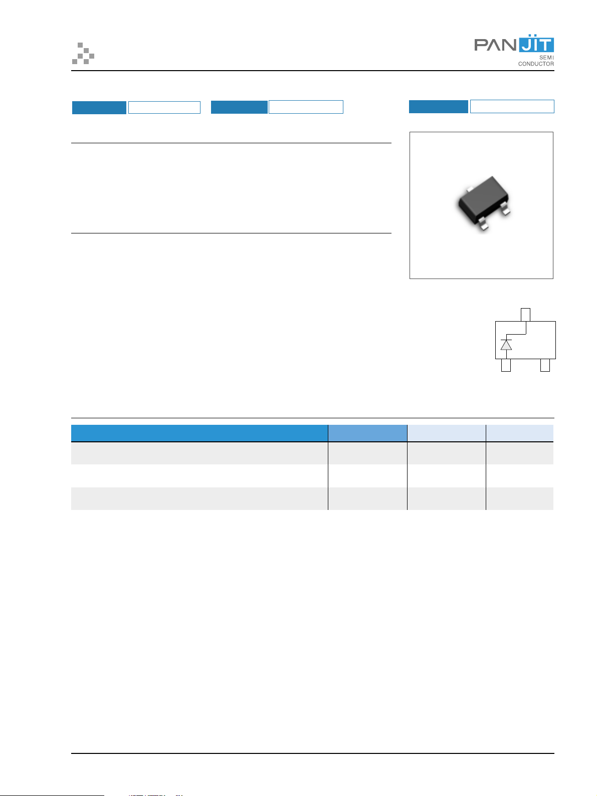
MMBZ5221BW thru MMBZ5259BW
SURFACE MOUNT SILICON ZENER DIODES
VOLTAGE
2.4 - 39 Volts
POWER
FEATURES
• Planar Die construction
• 200mW Power Dissipation
• Zener Voltages from 2.4V - 39V
• Ideally Suited for Automated Assembly Processes
MECHANICAL DATA
Case: SOT-323, Plastic
Terminals: Solderable per MIL-STD-202, Method 208
Approx. Weight: 0.008 gram
200 mWatts
PACKAGE SOT-323
SINGLE
MAXIMUM RATINGS AND ELECTRICAL CHARACTERISTICS
retemaraP lobmyS
O
52ta)AsetoN(noitapissiDrewoP
C
flahelgnissm3.8,tnerruCegruSdrawroFkaeP
)BsetoN()dohtemCEDEJ(daoldetarnodesopmirepusevaw-enis
egnaRerutarepmeTegarotSdnanoitcnuJgnitarepO
NOTES:
A. Mounted on 5.0mm2(.013mm thick) land areas.
B. Measured on 8.3ms, single half sine-wave or equivalent square wave, duty cycle = 4 pulses per minute maximum.
P
I
FSM
D
T
J
eulaV stinU
002 Wm
0.2spmA
051+ot55-
O
C
Part Number: MMBZ5221BW thru MMBZ5259BW PAGE 1
Page 2
MMBZ5221BW thru MMBZ5259BW
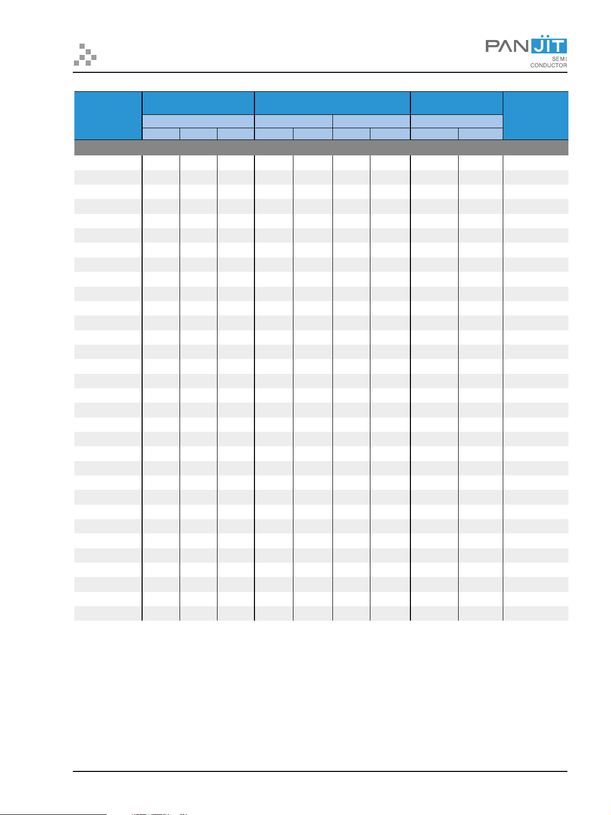
ELECTRICAL CHARACTERISTICS (TA=25OC unless otherwise noted) VF=1.2V max, IF=100mA for all types.
IR@V
esreveRxaM
tnerruCegakaeL
R
V
egatloVreneZlanimoN ecnadepmIreneZ.xaM
rebmuNtraP
VZ@I
ZT
V.moN V.niM V.xaM ΩΩΩΩΩ Am ΩΩΩΩΩ Am
ZZT@I
ZT
ZZK@I
ZK
µA
sedoiDreneZsttaWm002
WB1225ZBMM4.282.225.20302002152.00011 323-TOS
WB2225ZBMM 5.2 83.2 36.2 03 02 0521 52.0 001 1 323-TOS
WB3225ZBMM7.275.248.20302003152.0571 323-TOS
WB5225ZBMM 3 58.2 51.3 03 02 0061 52.0 05 1 323-TOS
WB6225ZBMM3.341.374.38202006152.0521 323-TOS
WB7225ZBMM 6.3 24.3 87.3 42 02 0071 52.0 51 1 323-TOS
WB8225ZBMM9.317.31.43202009152.0011 323-TOS
WB9225ZBMM 3.4 90.4 25.4 22 02 0002 52.0 5 1 323-TOS
WB0325ZBMM7.474.449.49102009152.052 323-TOS
WB1325ZBMM 1.5 58.4 63.5 71 02 0061 52.0 5 2 323-TOS
WB2325ZBMM6.523.588.51102006152.053 323-TOS
WB4325ZBMM 2.6 98.5 15.6 7 02 0001 52.0 5 4 323-TOS
WB5325ZBMM8.664.641.750205752.035 323-TOS
WB6325ZBMM 5.7 31.7 88.7 6 02 005 52.0 3 6 323-TOS
WB7325ZBMM2.897.716.880200552.036 323-TOS
WB9325ZBMM 1.9 56.8 65.9 01 02 006 52.0 3 5.6 323-TOS
WB0425ZBMM015.95.01710200652.038 323-TOS
WB1425ZBMM 11 54.01 55.11 22 02 006 52.0 3 4.8 323-TOS
WB2425ZBMM214.116.21030200652.021.9323-TOS
WB3425ZBMM 31 53.21 56.31 31 5.9 006 52.0 1 9.9 323-TOS
WB5425ZBMM5152.4157.51615.800652.05.011323-TOS
WB6425ZBMM 61 2.51 8.61 71 8.7 006 52.0 1.0 21 323-TOS
WB8425ZBMM811.719.81127 00652.01.041323-TOS
WB0525ZBMM 02 91 12 52 2.6 006 52.0 1.0 51 323-TOS
WB1525ZBMM229.021.32926.500652.01.071323-TOS
WB2525ZBMM 42 8.22 2.52 33 2.5 006 52.0 1.0 81 323-TOS
WB4525ZBMM7256.5253.8214500652.01.012323-TOS
WB5525ZBMM 82 6.62 4.92 44 5.4 006 52.0 1.0 12 323-TOS
WB6525ZBMM035.825.13942.400652.01.032323-TOS
WB7525ZBMM 33 53.13 56.43 85 8.3 007 52.0 1.0 52 323-TOS
WB8525ZBMM632.438.73074.300752.01.072323-TOS
WB9525ZBMM 93 50.73 59.04 08 2.3 008 52.0 1.0 03 323-TOS
egakcaP
NOTE:
1.Tolerance and Type Number Designation. The type numbers listed have a standard tolerance on the nominal zener voltage of ±5%.
2.Specials Available Include:
A. Nominal zener voltages between the voltages shown and tighter voltage tolerances.
B. Matched sets.
3.Zener Voltage (VZ) Measurement. Guarantees the zener voltage when measured at 90 seconds while maintaining the lead temperature (TL) at 30OC, from the diode body.
4.Zener Impedance (ZZ) Derivation. The zener impedance is derived from the 60 cycle ac voltage, which results when an AC current having an rms value equal to 10% of the dc zener
current (IZT or IZK) is superimposed on IZT or IZK.
5.Surge Current (IR) Non-Repetitive. The rating listed in the electrical characteristics table is maximum peak, non-repetitive, reverse surge current of 1/2 square wave or equivalent sine
wave pulse of 1/120 second duration superimposed on the test current, IZT, per JEDEC registration; however, actual device capability is as described in Figure 5.
Part Number: MMBZ5221BW thru MMBZ5259BW PAGE 2
Page 3

RATING and CHARACTERISTIC CURVES
o
TEMPERATURE COEFFICIENT,mV / C)
1000
100
8
7
6
5
4
3
2
1
0
-1
-2
-3
12111098765432
NOMINAL ZENER VOLTAGE, Volts
TYPICAL REVERSE CURRENT
O
TJ=25 C
I
Z(AC)=0.1
I
Z(DC)
IZ=1mA
F=1 kHZ
100
o
10
TEMPERATURE COEFFICIENT,mV / C)
1
10 100
NOMINAL ZENER VOLTAGE, Volts
STEADY STATE POWER DERATING
1000
100
5mA
20 mA
10
DYNAMIC IMPEDANCE, W
1
NORMAL ZENER VOLTAGE, Volts
EFFECT OF ZENER VOLTAGE ON ZENER IMPEDANCE
1.2
1.0
0.8
0.6
POWER DISSIPATION, Watts
0.4
0.2
0
PDV.S.T
A
TEMPERATURE ( C)
150125100755025
o
155
O
FORWARD CURRENT,mA
100101
150 C
10
O
75 C
25 C
1
O
O
5C
1.21.11.00.90.80.70.60.50.4
FORWARD VOLTAGE, Volts
TYPICAL FORWARD VOLTAGE
1000
CAPACITANCE, pF
100
10
1
0 V BIAS
1 V BIAS
BIAS AT
50% OF VZNOM
101
NOMINAL ZENER VOLTAGE, Volts
T =25 C
A
o
100
STEADY STATE POWER DERATING
TYPICAL CAPACITANCE
Part Number: MMBZ5221BW thru MMBZ5259BW PAGE 3
Page 4

RATING and CHARACTERISTIC CURVES
100
10
1
0.1
ZENER CURRENT,mA
0.01
ZENER VOLTAGE, Volts
ZENER VOLTAGE V.S. ZENER CURRENT
1000
100
10
1
0.1
0.01
0.001
LEAKAGE CURRENT ( A)m
0.0001
0.00001
T =25 C
A
+150 C
+25 C
o
1086420
O
-55 C
80706050403020100
100
o
T =25 C
A
10
1
0.1
ZENER CURRENT,mA
0.01
12
10 30 50 70 90
ZENER VOLTAGE, Volts
ZENER VOLTAGE V.S. ZENER CURRENT
O
O
90
NOMINAL ZENER VOLTAGE, Vlots
TYPICAL LEAKGE CURRENT
Part Number: MMBZ5221BW thru MMBZ5259BW PAGE 4
Page 5

OUTLINE DRAWING
)
)
1.35
1.15
(
(
.054
.045
.087(2.20
.070(1.80
.056(1.40
.047(1.20
)
)
)
)
SOT-323
.006(.15
.002(.05
MIN.
)
.25
(
.010
)
)
2.20
2.00
(
(
.087
.078
)
)
MAX.
)
.10
(
.004
)
.016(.40
)
.078(.20
© Copyright PanjIt International Inc. 2001
All rights are reserved. Reproduction in whole or in part is prohibited without the prior written consent of the copyright owner.
The information presented in this document does not form part of any quotation or contract, is believed to be accurate and reliable and may changed without notice. No liability will be
accepted by the publisher for any consequence of its use.
Publication thereof does not convey nor imply any license under patent or other industrial or intellectual property rights.
)
1.10
(
.044
)
.90
(
.035
PanJit Internatioal Inc.
TEL:886-7-6213121 Fax:886-7-6213129 Internet: http://www.panjit.com.tw email: sales@panjit.com.tw
Part Number: MMBZ5221BW thru MMBZ5259BW PAGE 5
 Loading...