

Page 1
SEMICONDUCTOR TECHNICAL DATA
±40g Amplified
The MMAS40G family of silicon capacitive, micro–machined accelerometers
features integral signal amplification, signal conditioning, a 4–pole low–pass
filter and temperature compensation. Zero–G offset, full scale span and filter
roll–off are factory set and require no external passives. A calibrated self–test
feature mechanically displaces the seismic mass with the application of a digital
self–test signal.
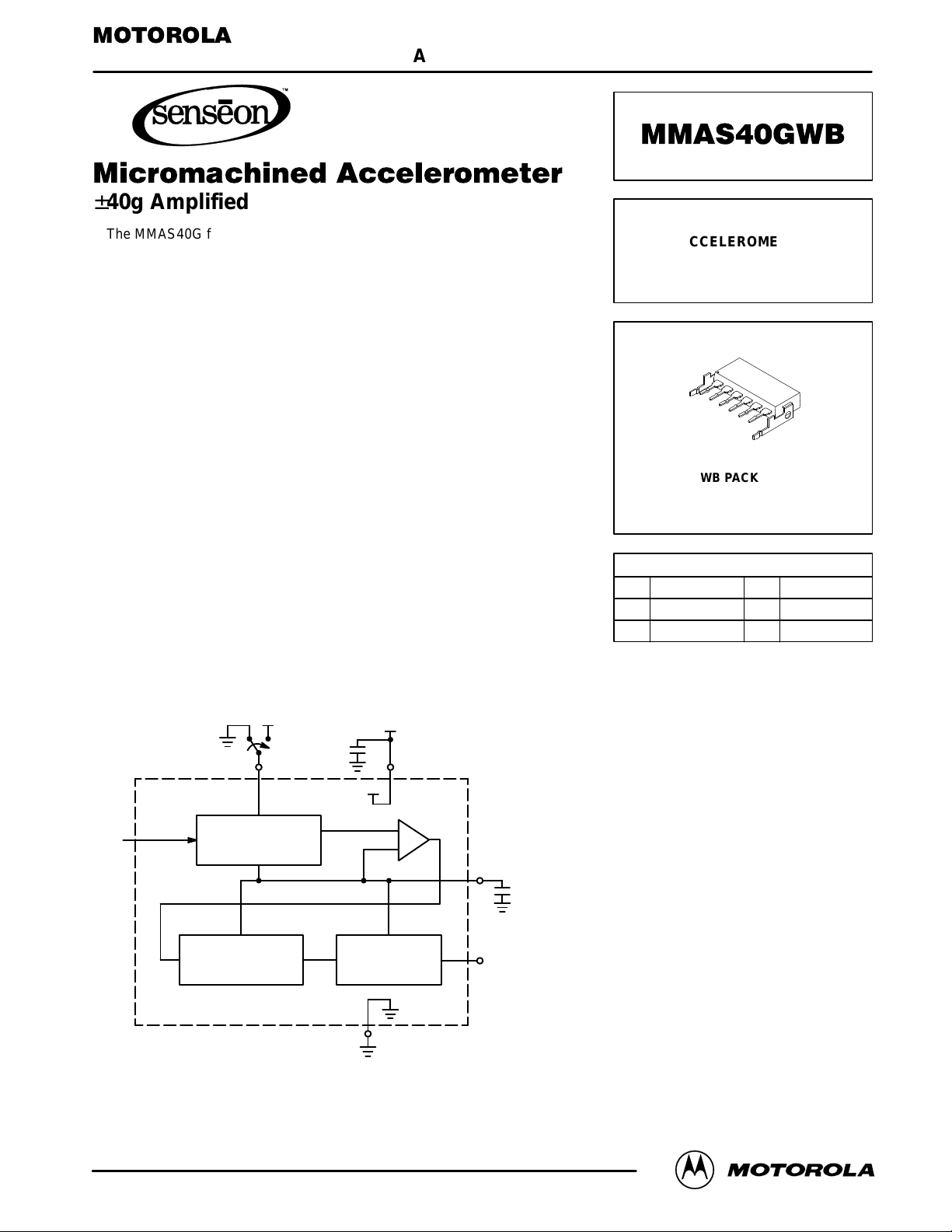
The MMAS40G incorporates a single polysilicon seismic mass, suspended
between two fixed polysilicon plates (G–cell). The forces of acceleration move
the seismic mass, thereby resulting in a change in capacitance. The G–cell is
sealed at the wafer level, creating a particle–free environment. The G–cell
features built–in damping and over–range stops to protect it from mechanical
shock.
MMAS40G accelerometers are ideally suited for automotive crash detection
and recording, vibration monitoring, automotive suspension control, appliance
control systems, etc.
Features
• Minimum Full Scale Measurement ±40g
• Calibrated, True Self–Test
• Senses Parallel to the Printed Circuit Board
• Integral Signal Conditioning and 4–Pole Filter
• Linear Output
• Robust, High Shock Survivability
SIMPLIFIED BLOCK DIAGRAM
+
+
Order this document
by MMAS40GWB/D
MICROMACHINED
ACCELEROMETER
±40g AMPLIFIED
(Wingback)
1
2
3
4
5
6
WB PACKAGE
CASE 456–03
PIN NUMBER (WB)
1 4
NC (1) V
25
Self–Test GND
36
Output VS (2)
NOTES:
1. Connect to ground.
2. Bypass at pin to ground with 0.1 µF
ceramic capacitor for specified performance.
ref
(2)
2 SELF–TEST
g
(Replaces XMMAS40GWB)
Motorola Sensor Device Data
Motorola, Inc. 1997
G–CELL
LOW–PASS FILTER
6V
S
+
A
TEMPERATURE
COMPENSATION
5 GND
4V
ref
3
OUTPUT
1
Page 2
MMAS40GWB
MAXIMUM RATINGS
Rating Symbol Value Unit
Acceleration (biased each axis) G ±500 g
Acceleration (unbiased each axis) G ±2000 g
Supply Voltage V
Storage Temperature T
Operating Temperature(6) T
Smax
stg
A
–0.3 to +7.0 Vdc
–40 to +105 °C
–40 to +85 °C
OPERATING CHARACTERISTICS (V
Characteristic Symbol Min Typ Max Unit
Acceleration Range G ±40 ±55 — g
Output Drive Capability — –0.2 — 0.2 mA
Supply Voltage V
Supply Current I
Full Scale Output Range V
Sensitivity (over temperature range) (2) (3) ∆V/∆G 36 40 44 mV/g
Zero Acceleration Output (over temperature range) (3) (4) V
Linearity — — 0.5 2.0 %FSO
Transverse Sensitivity — — 1.0 3.0 %FSO
Frequency Bandwidth — 300 400 500 Hz
Noise — — 15 25 mV
Self–Test Output Equivalent (5) G
Self–Test Input Low V
Self–Test Input High V
Self–Test Input Current — 10 70 200 µA
NOTES:
1. The output voltage increases from the Zero Acceleration Output for positive acceleration and decreases for negative acceleration. The
typical sensitivity is 40 mV/g. For example, with VS = 5.0 V , a +20g input will result in a 3.3 V output. (V
input will result in a 1.7 V output.
2. Sensitivity is a ratiometric parameter: ∆V/∆G
3. The compensated temperature operating range is –40 to +85°C.
4. Zero Acceleration Output is a ratiometric parameter: V
5. Equivalent output in response to a Logic Level One on the self–test pin.
6. Additional temperature range available. Consult factory.
= 5.0 Vdc, TA = 25°C unless otherwise noted)
S
S
O
FSO
off
S
STL
STH
(Vs)
= ∆V/∆G
off(Vs)
x (VS/5 V).
(5 V)
= V
off(5 V)
x (VS/5 V).
4.75 5.0 5.25 V
— 5.0 7.0 mA
0.3 — VS – 0.3 V
2.2 2.5 2.8 V
20 25 30 g
— — 1.6 V
3.4 — — V
= 2.5 + 0.040 x 20) and a –20g
output
pk
ORDERING INFORMATION
Device Temperature Range Case No. Package
MMAS40GWB –40 to +85°C 456–03 Plastic Wingback
2
Motorola Sensor Device Data
Page 3

POSITIVE ACCELERATION SENSING DIRECTION
MMAS40GWB
12
16
7
*
Earth’s
Surface
WINGBACK PACKAGE
* When positioned as shown, the earth’s gravity will result in a positive 1g output
WINGBACK PACKAGE DRILLING PATTERN
.100 .200 .300 .400 .500
.000
0.088 0.588
.13
PIN 1
.627
∅
.045 2X
.095 2X
.000
∅
.030 6X
Measurement in inches
Motorola Sensor Device Data
3
Page 4

MMAS40GWB
P ACKAGE DIMENSIONS
–A–
C
12
7
–B–
16
L
K
M
G
H
0.13 (0.005) B
6 PL
D
M
M
A
T
J
S
M
NOTES:
1. DIMENSIONING AND TOLERANCING PER ANSI
Y14.5M, 1982.
2. CONTROLLING DIMENSION: INCH.
DIM MIN MAX MIN MAX
A 15.700.6380.618 16.21
B 6.350.2700.250 6.86
C 3.300.1350.130 3.43
D 0.380.0210.015 0.53
E 8.330.3680.328 9.35
F 2.840.112 3.050.120
G 0.100 BSC 2.54 BSC
H 0.050 BSC 1.27 BSC
J 0.009 0.012 0.23 0.30
K 0.125 0.140 3.18 3.56
L 0.063 0.070 1.60 1.78
M 0.015 0.025 0.38 0.64
N 0.036 0.044 0.91 1.12
P 0.110 0.120 2.79 3.05
N
S 0.025 0.035 0.64 0.89
MILLIMETERSINCHES
P
E
F
–T–
CASE 456–03
ISSUE D
WB P ACKAGE
Motorola reserves the right to make changes without further notice to any products herein. Motorola makes no warranty , representation or guarantee regarding
the suitability of its products for any particular purpose, nor does Motorola assume any liability arising out of the application or use of any product or circuit, and
specifically disclaims any and all liability, including without limitation consequential or incidental damages. “T ypical” parameters which may be provided in Motorola
data sheets and/or specifications can and do vary in different applications and actual performance may vary over time. All operating parameters, including “Typicals”
must be validated for each customer application by customer’s technical experts. Motorola does not convey any license under its patent rights nor the rights of
others. Motorola products are not designed, intended, or authorized for use as components in systems intended for surgical implant into the body, or other
applications intended to support or sustain life, or for any other application in which the failure of the Motorola product could create a situation where personal injury
or death may occur. Should Buyer purchase or use Motorola products for any such unintended or unauthorized application, Buyer shall indemnify and hold Motorola
and its officers, employees, subsidiaries, affiliates, and distributors harmless against all claims, costs, damages, and expenses, and reasonable attorney fees
arising out of, directly or indirectly, any claim of personal injury or death associated with such unintended or unauthorized use, even if such claim alleges that
Motorola was negligent regarding the design or manufacture of the part. Motorola and are registered trademarks of Motorola, Inc. Motorola, Inc. is an Equal
Opportunity/Affirmative Action Employer.
How to reach us:
USA/EUROPE/Locations Not Listed: Motorola Literature Distribution; JAPAN: Nippon Motorola Ltd.: SPD, Strategic Planning Office, 4–32–1,
P.O. Box 5405, Denver , Colorado 80217. 303–675–2140 or 1–800–441–2447 Nishi–Gotanda, Shinagawa–ku, Tokyo 141, Japan. 81–3–5487–8488
Mfax: RMFAX0@email.sps.mot.com – TOUCHTONE 602–244–6609 ASIA/PACIFIC: Motorola Semiconductors H.K. Ltd.; 8B Tai Ping Industrial Park,
INTERNET: http://motorola.com/sps
4
– US & Canada ONLY 1–800–774–1848 51 Ting Kok Road, T ai Po, N.T., Hong Kong. 852–26629298
◊
Mfax is a trademark of Motorola, Inc.
Motorola Sensor Device Data
MMAS40GWB/D
 Loading...