

Page 1
查询MM74C373供应商
MM74C373 • MM74C374
3-STATE Octal D-Type Latch •
3-STATE Octal D-Type Flip-Flop
MM74C373 • MM74C374 3-STATE Octal D-T ype Latch • 3-STATE Octal D-Type Flip-Flop
October 1987
Revised January 1999
General Description
The MM74C373 and MM74C374 are integrated, complementary MOS (CMOS), 8-bit storage elements with 3STATE outputs. These outputs have been specially
designed to drive high capaci tive loads, such as on e might
find when driving a bus, and to have a fan out of 1 when
driving standard TT L. When a high l ogic level is applied to
the OUTPUT DISABLE input, all outputs go to a high
impedance state, regardless of what sig nals are prese nt at
the other inputs and the state of the storage elements.
The MM74C373 is an 8-bit latch. When LATCH
high, the Q outputs will follow the D inputs. When LATCH
ENABLE goes low, data at the D inputs, which meets the
set-up and hold time requirements, will be retained at the
outputs until LATCH
The MM74C374 is an 8-bit, D-type, positive-edge triggered
flip-flop. Data at the D input s, meeting the set-up and hold
time requirements, is transferred to th e Q outpu ts on positive-going transitions of the CLOCK input.
ENABLE returns high again.
ENABLE is
Both the MM74C373 and the MM74C374 are being assem-
bled in 20-pin dual-i n-line packages with 0.300” pin centers.
Features
■ Wide supply voltage range: 3V to 15V
■ High noise immunity: 0.45 V
■ Low power consumption
■ TTL compatibility:
Fan out of 1driving standard TTL
■ Bus driving capability
■ 3-STATE outputs
■ Eight storage elements in one package
■ Single CLOCK/LATCH
ABLE control inputs
■ 20-pin dual-in-line package with 0.300” centers takes
half the board space of a 24-pin package
(typ.)
CC
ENABLE and OUTPUT DIS-
Ordering Code:
Order Number Package Number Package Description
MM74C373M M20B 20-Lead Small Outline Integrated Circuit (SOIC), JEDEC MS-013, 0.300” Wide
MM74C373N N20A 20-Lead Plastic Dual-In-Line Package (PDIP), JEDEC MS-001, 0.300” Wide
MM74C374M M20B 20-Lead Small Outline Integrated Circuit (SOIC), JEDEC MS-013, 0.300” Wide
MM74C374N N20A 20-Lead Plastic Dual-In-Line Package (PDIP), JEDEC MS-001, 0.300” Wide
Devices also available in Tape and Reel. Specify by appending the suffix letter “X” to t he ordering code.
© 1999 Fairchild Semiconductor Corporation DS005906.prf www.fairchildsemi.com
Page 2
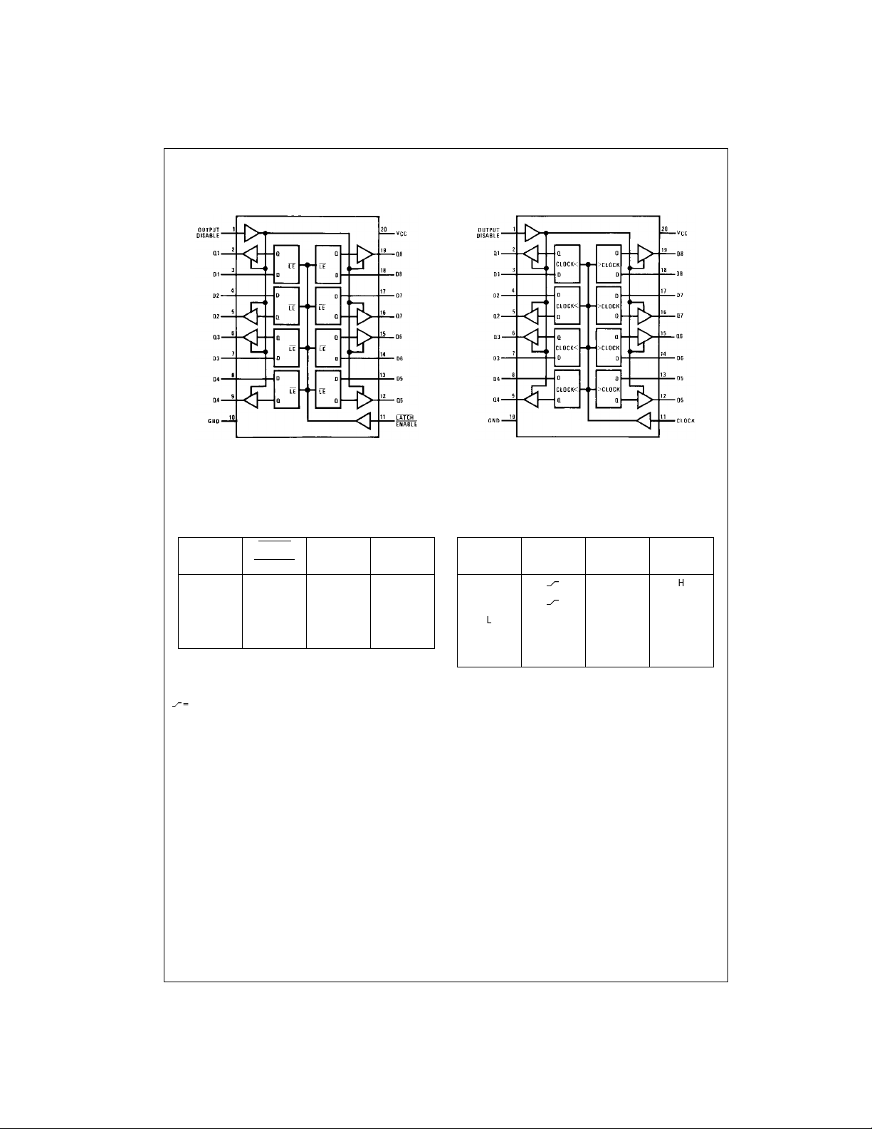
Connection Diagrams
MM74C373
MM74C373 • MM74C374
Pin Assignments for DIP and SOIC
MM74C374
Top View
Truth Tables
MM74C373 MM74C374
Output LATCH DQ
Disable ENABLE
LHHH
LHLL
LLXQ
H X X Hi-Z
L = LOW logic level
H = HIGH logic level
X = Irrelevant
= LOW-to-HIGH logic level transition
Q = Preexisting output level
Hi-Z = High impedance output state
Top View
Output Clock D Q
Disable
L
L
LLXQ
LHXQ
H X X Hi-Z
HH
LL
www.fairchildsemi.com 2
Page 3
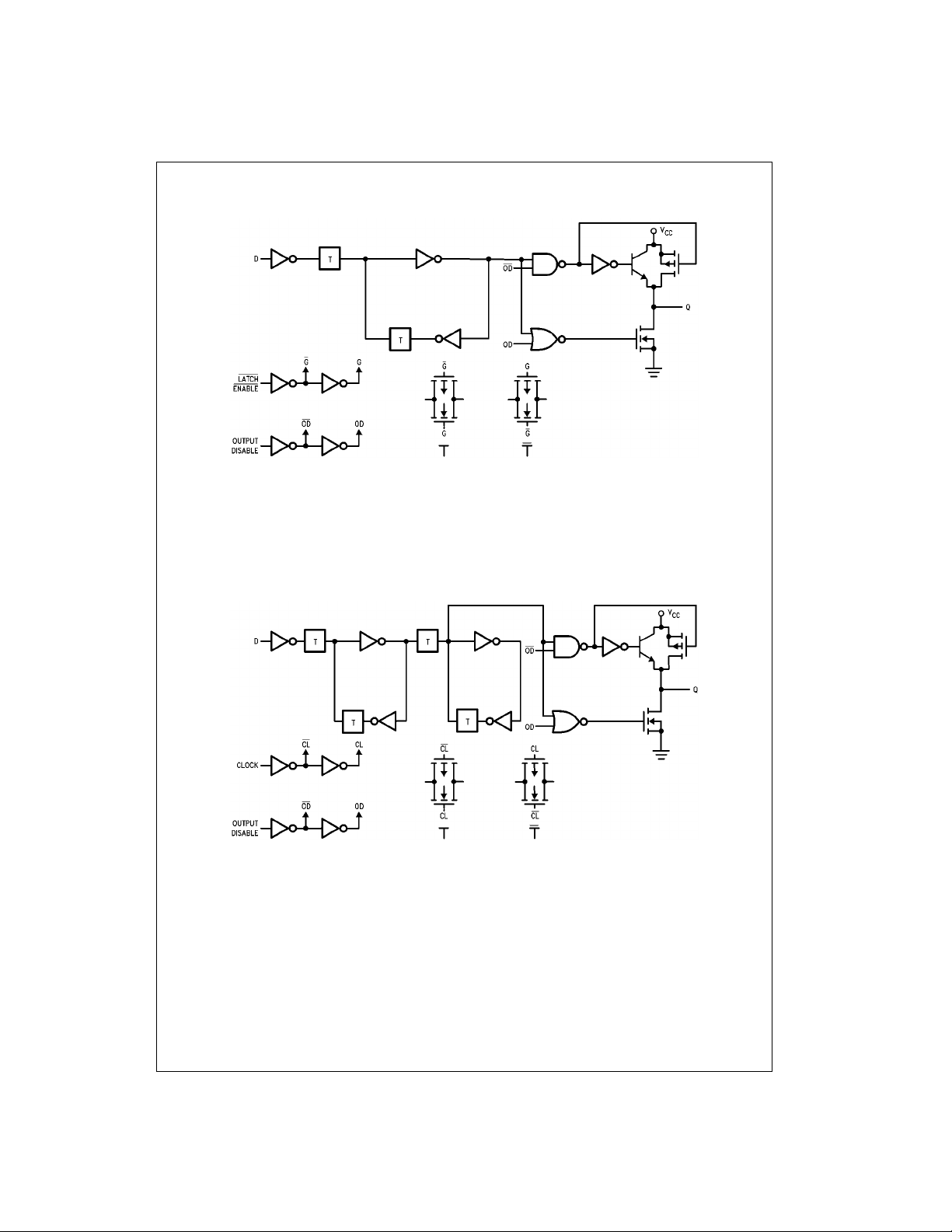
Block Diagrams
MM74C373 • MM74C374
MM74C373 (1 of 8 Latches)
MM74C374 (1 of 8 Flip-Flops)
3 www.fairchildsemi.com
Page 4
Absolute Maximum Ratings(Note 1)
Voltage at Any Pin −0.3V to VCC + 0.3V
Operating Temperature Range (T
MM74C373 −40°C to +85°C
Storage Temperature Range (T
Power Dissipation
Dual-In-Line 700 mW
Small Outline 500 mW
MM74C373 • MM74C374
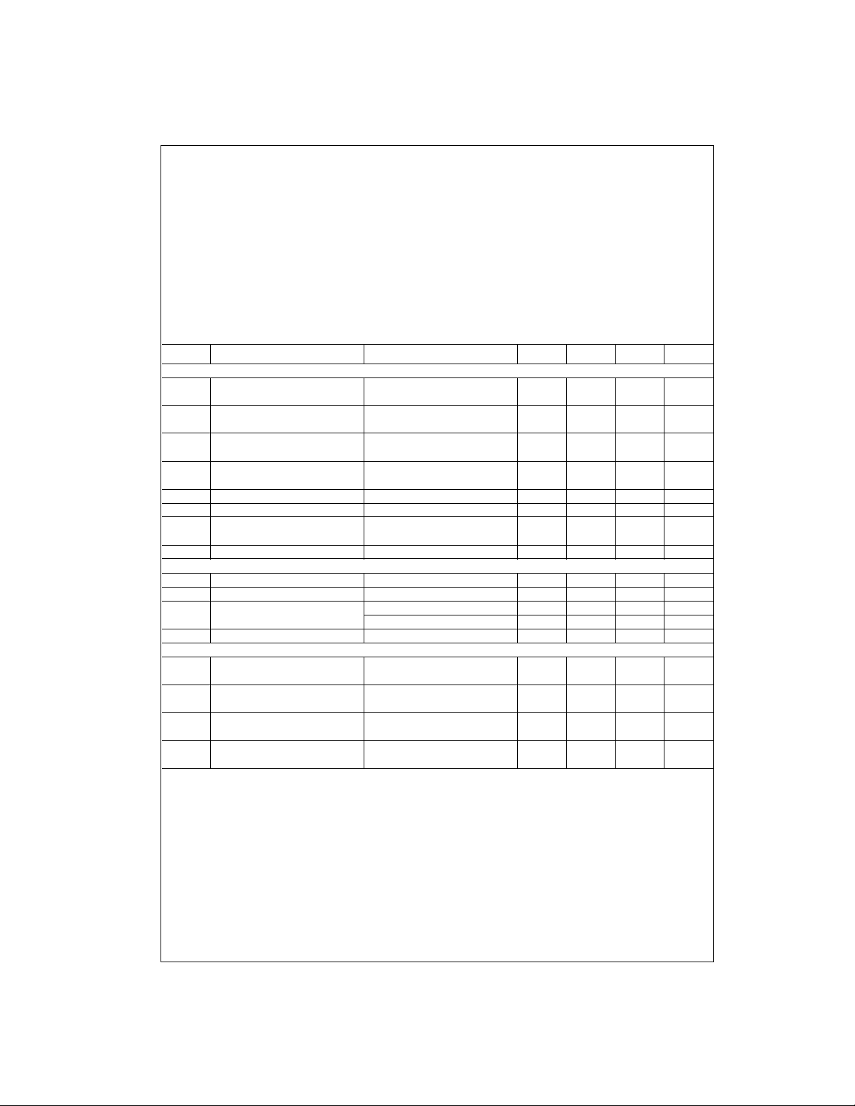
DC Electrical Characteristics
)
A
) −65°C to +150°C
S
Operating V
Absolute Maximum V
Lead Temperature (T
(Soldering, 10 seconds) 260°C
Note 1: “Absolute Maxi mum Ratings” are those valu es beyond which the
safety of the device cannot be guaranteed. Ex ce pt for “O perating Temperature Range” they are not mean t to imply that the devices sho uld be operated at these limits. The table of “Electrical Characteristics” provides
conditions for actual device op eration.
Range 3V to 15V
CC
CC
)
L
Min/Max limits apply across temperature range unless otherwise noted
Symbol Parameter Conditions Min Typ Max Units
CMOS TO CMOS
V
IN(1)
Logical “1” Input Voltage VCC = 5V 3.5 V
VCC = 10V 8.0 V
V
IN(0)
Logical “0” Input Voltage VCC = 5V 1.5 V
VCC = 10V 2.0 V
V
OUT(1)
Logical “1” Output Voltage VCC = 5V, IO = −10 µA4.5 V
VCC = 10V, IO = −10 µA9.0 V
V
OUT(0)
Logical “0” Output Voltage VCC = 5V, IO = 10 µA0.5V
VCC = 10V, IO = 10 µA1.0V
I
I
I
IN(1)
IN(0)
OZ
Logical “1” Input Current VCC = 15V, VIN = 15V 0.005 1.0 µA
Logical “0” Input Current VCC = 15V, VIN = 0V −1.0 −0.005 µA
3-STATE Leakage Current VCC = 15V, VO = 15V 0.005 1.0 µA
VCC = 15V, VO = 0V −1.0 −0.005 µA
I
CC
Supply Current VCC = 15V 0.05 300 µA
CMOS/LPTTL INTERFA CE
V
IN(1)
V
IN(0)
V
OUT(1)
Logical “1” Input Voltage VCC = 4.75V VCC − 1.5 V
Logical “0” Input Voltage VCC = 4.75V 0.8 V
Logical “1” Output Voltage VCC = 4.75V, IO = −360 µAV
− 0.4 V
CC
VCC = 4.75V, IO = −1.6 mA 2.4 V
V
OUT(0)
Logical “0” Output Voltage VCC = 4.75V, IO = 1.6 mA 0.4 V
OUTPUT DRIVE (Short Circuit Current)
I
SOURCE
Output Source Current VCC = 5V, V
= 0V −12 −24 mA
OUT
TA = 25°C (Note 2)
I
SOURCE
Output Source Current VCC = 10V, V
= 0V −24 −48 mA
OUT
TA = 25°C (Note 2)
I
SINK
Output Sink Current VCC = 5V, V
OUT
= V
CC
612 mA
(N-Channel) TA = 25°C (Note 2)
I
SINK
Output Sink Current VCC = 10V, V
OUT
= V
CC
24 48 mA
(N-Channel) TA = 25°C (Note 2)
Note 2: These are peak output current capabilities. Continuous output current is rated at 12 mA max.
18V
www.fairchildsemi.com 4
Page 5
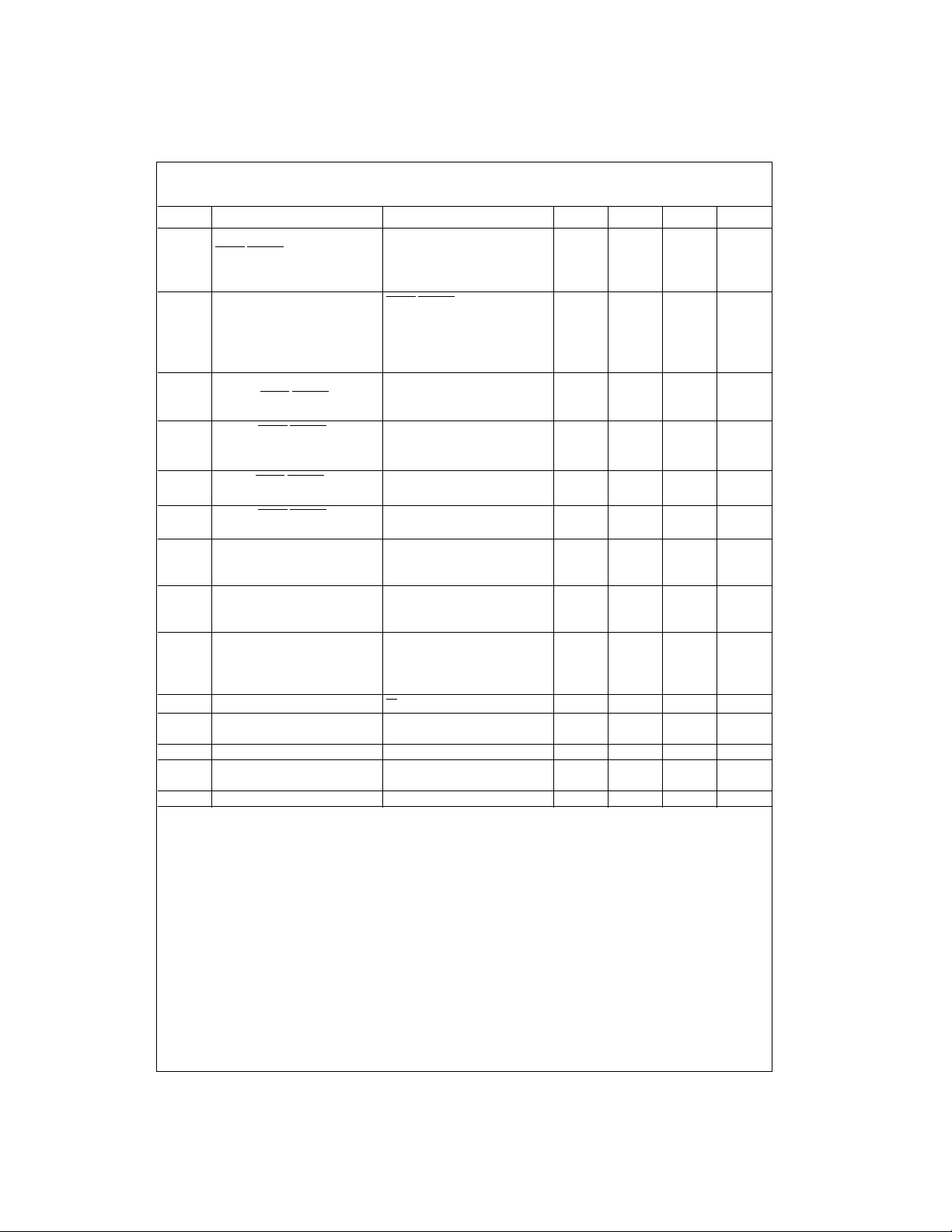
AC Electrical Characteristics (Note 3)
MM74C373, TA = 25°C, CL = 50 pF, tr = tf = 20 ns, unless otherwise noted
Symbol Parameter Conditions Min Typ Max Units
t
, t
pd0
t
pd0
t
SET-UP
f
MAX
t
PWH
tr, t
t1H, t
tH1, t
t
THL
C
LE
C
OD
C
IN
C
OUT
C
PD
Note 3: AC Parameters are guaranteed by DC correlated testing.
Note 4: Capacitance is guaranteed by periodic testing.
Note 5: C
AN-90.
Propagation Delay, VCC = 5V, CL = 50 pF 165 330 ns
pd1
LATCH ENABLE to Output
VCC = 10V, CL = 50 pF 70 140 ns
VCC = 5V, CL = 150 pF 195 390 ns
VCC = 10V, CL = 150 pF 85 170 ns
, t
Propagation Delay Data
pd1
LATCH ENABLE = V
CC
In to Output VCC = 5V, CL = 50 pF 155 310 ns
VCC = 10V, CL = 50 pF 70 140 ns
VCC = 5V, CL = 150 pF 185 370 ns
VCC = 10V, CL = 150 pF 85 170 ns
Minimum Set-Up Time Data In t
to CLOCK/LATCH ENABLE
= 0 ns
HOLD
VCC = 5V 70 140 ns
VCC = 10V 35 70 ns
Maximum LATCH ENABLE
Frequency VCC = 5V 3.5 6.7 MHz
VCC = 10V 4.5 9.0 MHz
Minimum LATCH ENABLE
VCC 5V 75 150 ns
Pulse Width VCC = 10V 55 110 ns
f
Maximum LATCH ENABLE
VCC = 5V NA µs
Rise and Fall Time VCC = 10V NA µs
Propagation Delay OUTPUT RL = 10k, CL = 5 pF
0H
DISABLE to High Impedance VCC = 5V 105 210 ns
State (from a Logic Level) VCC = 10V 60 120 ns
Propagation Delay OUTPUT RL = 10k, CL = 50 pF
H0
DISABLE to Logic Level VCC = 5V 105 210 ns
(from High Impedance State) VCC = 10V 45 90 ns
, t
Transition Time VCC = 5V, CL = 50 pF 65 130 ns
TLH
VCC = 10V, CL = 50 pF 35 70 ns
VCC = 5V, CL = 150 pF 110 220 ns
VCC = 10V, CL = 150 pF 70 140 ns
Input Capacitance
LE Input (Note 4)
7.5 10 pF
Input Capacitance OUTPUT DISABLE 7.5 10 pF
Input (Note 4)
Input Capacitance Any Other Input (Note 4) 5 7.5 pF
Output Capacitance High Impedance 10 15 pF
State (Note 4)
Power Dissipation Capacitance Per Package (Note 5) 200 pF
determines th e no load AC power consumption of any CMOS device. For complete explanation see Family Characteristics Application Note
PD
MM74C373 • MM74C374
5 www.fairchildsemi.com
Page 6

AC Electrical Charac teristics (Note 6)
MM74C374, TA = 25°C, CL = 50 pF, tr = tf = 20 ns, unless otherwise noted
Symbol Parameter Conditions Min Typ Max Units
t
, t
pd0
t
SET-UP
t
PWH
MM74C373 • MM74C374
f
MAX
t1H, t
tH1, t
t
THL
tr, t
C
CLK
C
OD
C
IN
C
OUT
C
PD
Note 6: AC Parameters are guara nt eed by DC correlated testing.
Note 7: Capacitance is guaranteed by periodic testing.
Note 8: C
AN-90.
Propagation Delay, VCC = 5V, CL = 50 pF 150 300 ns
pd1
CLOCK to Output VCC = 10V, CL = 50 pF 65 130 ns
VCC = 5V, CL = 150 pF 180 360 ns
VCC = 10V, CL = 150 pF 80 160 ns
Minimum Set-Up Time Data In t
to CLOCK/LATCH ENABLE
= 0 ns
HOLD
VCC = 5V 70 140 ns
VCC = 10V 35 70 ns
, t
Minimum CLOCK Pulse Width VCC = 5V 70 140 ns
PWL
VCC = 10V 50 100 ns
Maximum CLOCK Frequency VCC = 5V 3.5 7.0 MHz
VCC = 10V 5 10 MHz
Propagation Delay OUTPUT RL = 10k, CL = 50 pF
0H
DISABLE to High Impedance VCC = 5V 105 210 ns
State (from a Logic Level) VCC = 10V 60 120 ns
Propagation Delay OUTPUT RL = 10k, CL = 50 pF
H0
DISABLE to Logic Level VCC = 5V 105 210 ns
(from High Impedance State) VCC = 10V 45 90 ns
, t
Transition Time VCC = 5V, CL = 50 pF 65 130 ns
TLH
VCC = 10V, CL = 50 pF 35 70 ns
VCC = 5V, CL = 150 pF 110 220 ns
VCC = 10V, CL = 150 pF 70 140 ns
Maximum CLOCK Rise VCC = 5V 15 >2000 µs
f
and Fall Time VCC = 10V 5 >2000 µs
Input Capacitance CLOCK Input (Note 7) 7.5 10 pF
Input Capacitance OUTPUT DISABLE 7.5 10 pF
Input (Note 7)
Input Capacitance Any Other Input (Note 7) 5 7.5 pF
Output Capacitance High Impedance 10 15 pF
State (Note 7)
Power Dissipation Capacitance Per Package (Note 8) 250 pF
determines the no load AC power consumption of any C M OS device. For complete explanation se e Family Characteristics Applic ation Note
PD
www.fairchildsemi.com 6
Page 7
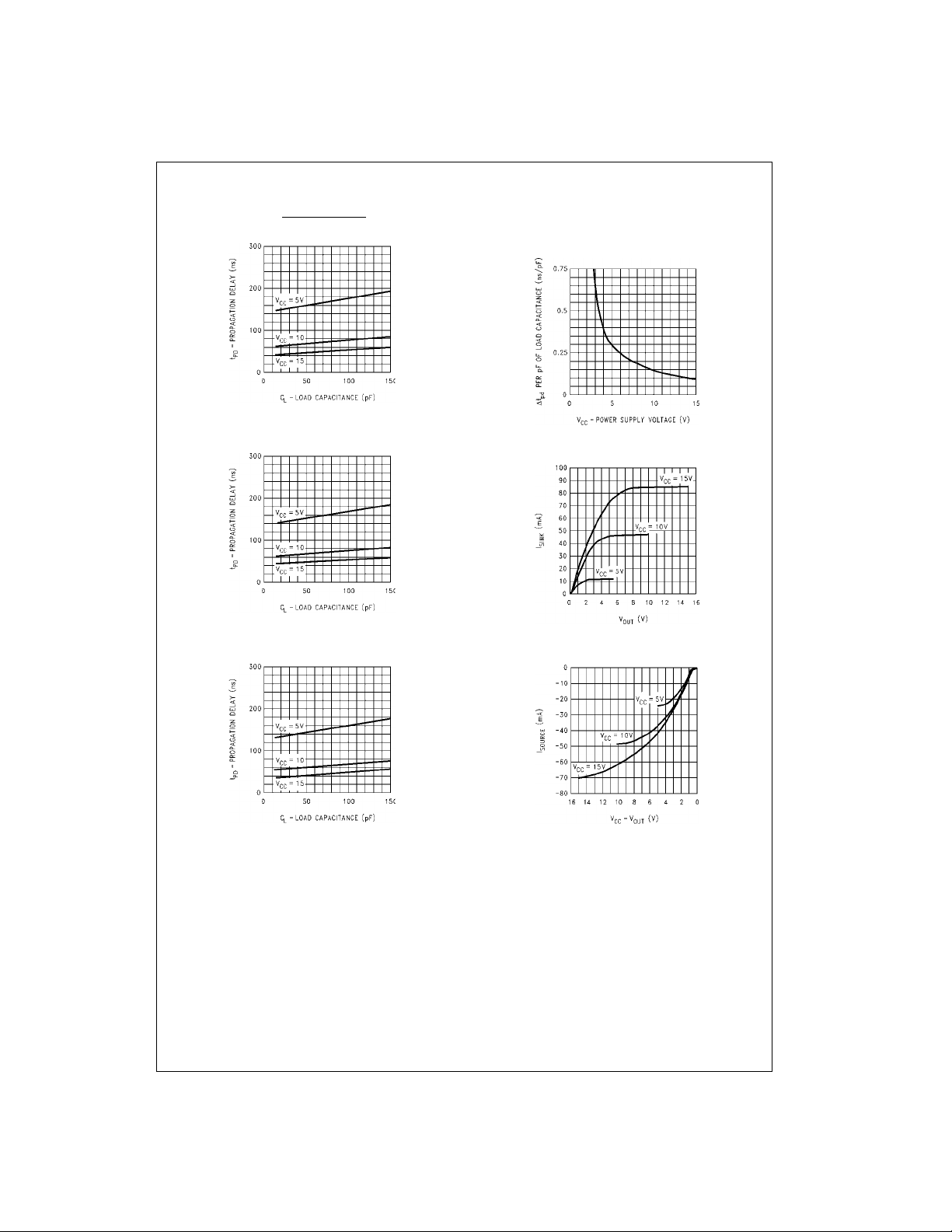
Typical Performance Charact eristics
MM74C373 • MM74C374
Propagation Delay, LATCH ENABLE
MM74C373
Load Capacitance
MM74C373
Propagation Delay, Data In to Output
vs Load Capac itance
MM74C373
Propagation Delay, CLOCK to Output
vs Load Capac itance
to Output vs
MM74C373, MM74C374
Change in Propagation Delay
per pF of Load Capacitance
/pF) vs Power Supply Voltage
(∆t
PD
MM74C373, MM74C374
Output Sink Current vs V
MM74C373, MM74C374
Source Current vs V
CC
− V
OUT
OUT
7 www.fairchildsemi.com
Page 8
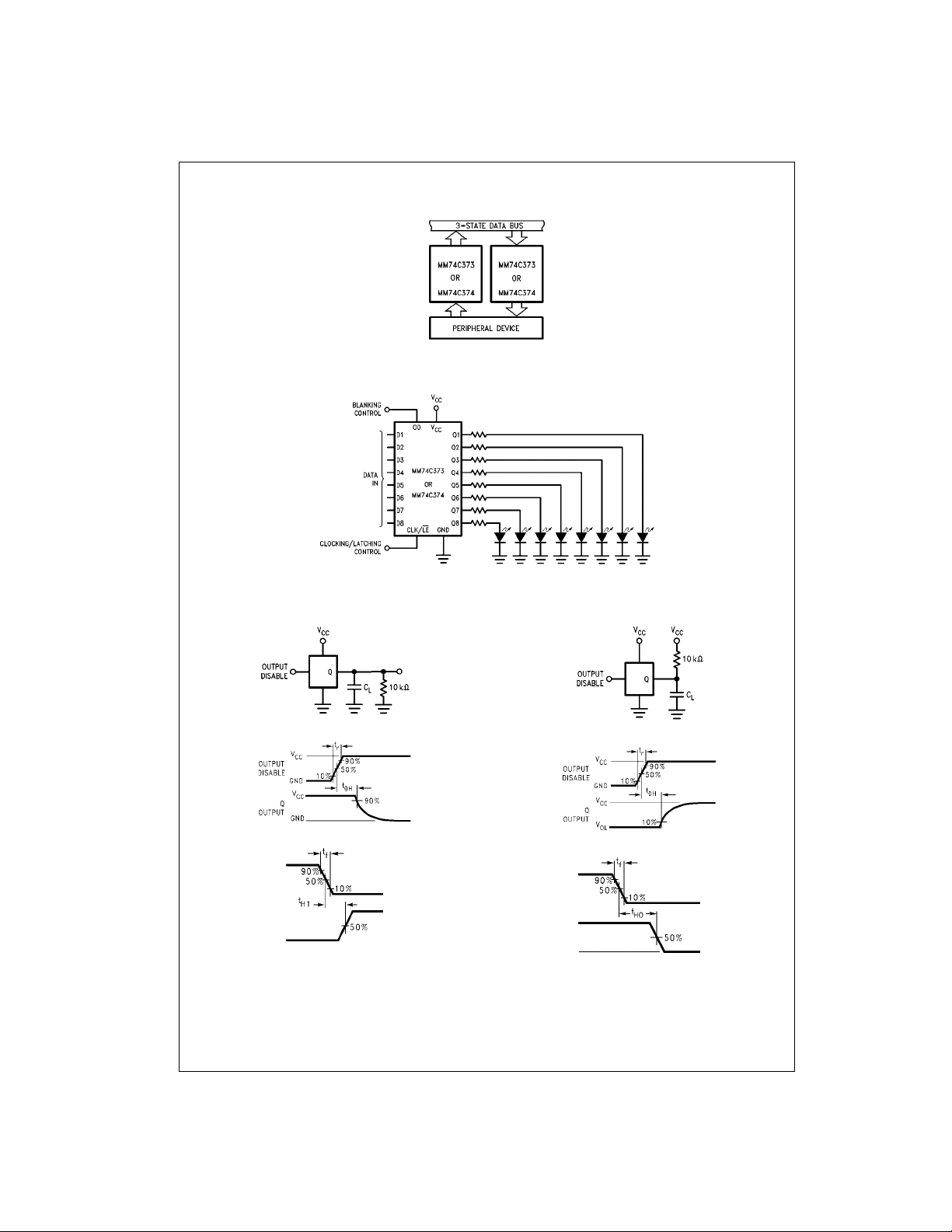
Typical Applications
Data Bus Interfacing Element
MM74C373 • MM74C374
Simple, Latching, Octal, LED Indicator
Driver with Blanking for Use as Data Display,
Bus Monitor, µP Front Panel Displa y, Etc.
3-STATE Test Circuits and Switching Time Waveforms
t1H, t
H1
t1H, CL = 5 pF
t
0H
, CL = 5 pF
t
0H
, tH0
, CL = 50 pF
t
H1
www.fairchildsemi.com 8
, CL = 50 pF
t
H0
Page 9
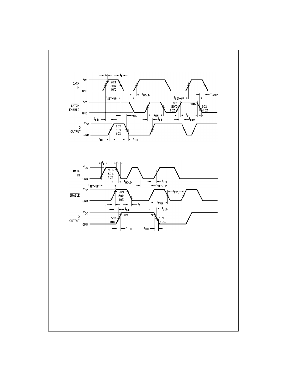
Switching Time Waveforms
Output Disable = GND
MM74C373 • MM74C374
MM74C373
MM74C374
Output Disable = GND
9 www.fairchildsemi.com
Page 10

Physical Dimensions in ches (millimeters) unless otherwise noted
MM74C373 • MM74C374
20-Lead Small Outline Integrated Circuit (SOIC), JEDEC MS-013. 0.300” Wide
Package Number M20B
www.fairchildsemi.com 10
Page 11
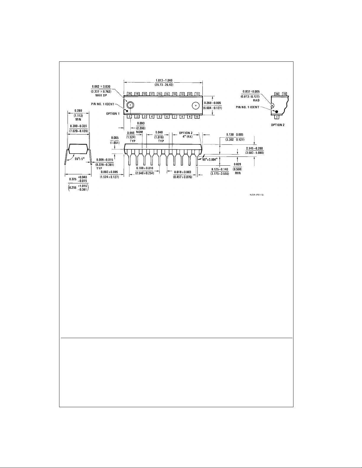
Physical Dimensions inches (millimeters) unless otherwise noted (Continued)
MM74C373 • MM74C374 3-STATE Octal D-Type Latch • 3-STATE Octal D-Type Flip-Flop
20-Lead Plastic Dual-In-Line Package (PDIP), JEDEC MS-001, 0.300” Wide
LIFE SUPPORT POLICY
FAIRCHILD’S PRODUCTS ARE NOT AUTHORIZED FOR USE AS CRITICAL COMPONENTS IN LIFE SUPPORT
DEVICES OR SYSTEMS WITHOUT THE EXPRESS WRITTEN APPROVAL OF THE PRESIDENT OF FAIRCHILD
SEMICONDUCTOR CORPORATION. As used herein:
1. Life support devices or system s a re devices or syste ms
which, (a) are intended for surgical implant into the
body, or (b) support or sustain life, and (c) whose failure
to perform when properly used in accordance with
instructions for use provided in the labeling, can be reasonably expected to result in a significant injur y to the
user.
Package Number N20A
2. A critical comp onent in any com ponent of a l ife support
device or system whose failure to perform can be reasonably expected to cause the failure of the life suppor t
device or system, or to affect its safety or effectiveness.
www.fairchildsemi.com
Fairchild does not assume any responsibility for use of any circuitry described, no circuit patent licenses are implied and Fairchild reserves the right at any time without notice to change said circuitry and specifications.
 Loading...