

Page 1
MITSUMI
Remaining Battery Power Display MM1251, MM1252, MM1253
Remaining Battery Power Display
Monolithic IC MM1251, MM1252, MM1253
This IC detects battery voltage and displays the power remaining in the battery. Display of the battery's
remaining power is an indispensable function for portable equipment. The use of this IC makes this display
easily achievable.
The usual method of display of remaining battery power, as in the MM1206, is three marks lighting up in
sequence on an LED or other display. This IC, however, uses only one light to display the remaining battery
power, resulting in lower cost.
Outline
Features
1. Adjustable flashing speed
2. Adjustable detection voltage supports all settings
3. Adjustable hysteresis voltage enables response to large ripple settings
4. High precision voltage detection (MM1253) enables support of sets using nickel cadmium and other
batteries
5. The LED can be lit up by the voltage from one battery (type of special built-in step-up circuit : rank B)
Package
SOP-8D (MM1251AF, MM1251BF, MM1252AF, MM1252BF, MM1253AF)
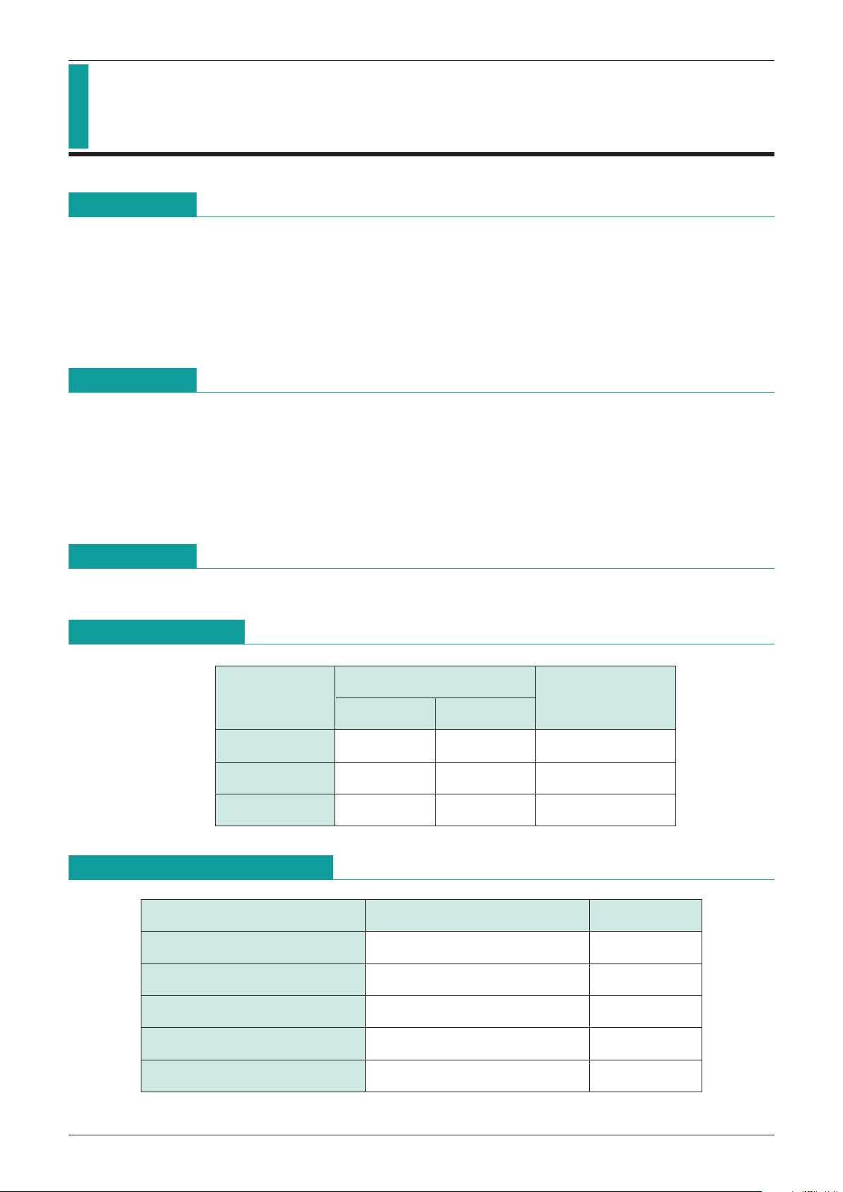
Series Description
Display Pattern
Normal Low Power
Detection Precision
MM1251 Light Off Flashing ±30mV
MM1252 Light On Flashing ±30mV
MM1253 Light Off Flashing ±9mV
Absolute Maximum Ratings
(Ta=25°C)
Item Rating Unit
Storage temperature
-
40~+125 °C
Operating temperature
-
20~+70 °C
Input voltage
-
0.3~+3 V
Output Terminal Applied Voltage
-
0.3~+7 V
Allowable loss 300 mW
Page 2

MITSUMI
Remaining Battery Power Display MM1251, MM1252, MM1253
Electrical Characteristics
(Unless otherwise specified Ta=25°C, Vc=1.5V, Vs=0.8V)
(Applicable to all models when the model name is left blank.)
Item Symbol
Measurement Conditions
Min. Typ. Max. Unit
V
S=1.0V
MM1251
25 40 µA
Current consumption 1 I
CC1
MM1253A
VCT=0.4V
MM1252A
0.15 0.25 mA
MM1252B
0.75 0.1 mA
MM1251A
0.15 0.25 mA
Current consumption 2 I
CC2VS=0.8V, VCT=0.4V
MM1253A
MM1251B
25 40 µA
V
S=1V 0.5V
MM1251
0.82 0.85 0.88 V
Detection voltage VD
V
HYS
<
=
0.1V
MM1252
MM1253 0.841 0.85 0.859 V
Detection voltage temperature factor
V/ T ±200
PPM/°C
HYS pin saturation voltage 1 VHYS1IHYS=5µA 25 50 mV
HYS pin saturation voltage 2 V
HYS2IHYS=25µA 50 100 mV
C
T pin charge current ICTS VCT=0.1V
-
60-40-20 nA
C
T pin discharge current ICTO VCT=0.4V 20 40 60 nA
C
T pin threshold value H VCTH VCT=0.1 0.4, VO
<
=
0.1V 0.2 0.3 0.4 V
C
T pin threshold value L VCTL VCT=0.4 0.1, VO
>
=
0.1V 0.1 0.2 0.3 V
Output sink current I
OUT VCR=0.4V 5 10 mA
Output saturation voltage I
OUTLVCT=0.4, IOUT=1mA 100 150 mA
Output leak current I
LE VS=1V, VOUT=5V 1 µA
Operating limit voltage V
OPR VS=0.8 VCCVOUT > 0.4V Rank A 0.65 0.75 V
V
S=0.8 VCC
Step-up operation limit voltage VOPL
VCC=0.1V 0.5V
Rank B 0.85 0.95 V
Voltage limit for maintaining
LED flashing
Page 3

MITSUMI
Remaining Battery Power Display MM1251, MM1252, MM1253
MM1251A/MM1253A
Application Circuit
Timing Chart
unsettled
V
CC
CT
OUT
VD
Page 4

MITSUMI
Remaining Battery Power Display MM1251, MM1252, MM1253
MM1251B
Application Circuit
Timing Chart
unsettled
V
CC
CT
VD
OUT
Page 5

MITSUMI
Remaining Battery Power Display MM1251, MM1252, MM1253
MM1252A
Application Circuit
Timing Chart
unsettled
V
CC
CT
VD
OUT
Page 6

MITSUMI
Remaining Battery Power Display MM1251, MM1252, MM1253
Step-up (Rank B) Type Inductor Values
This circuit allows step-up for LED lighting even when low only. The LED repeats On/Off at high frequency,
but to the human eye it appears as if the LED is lit. Therefore, we do not recommend the use of this step-up
circuit in other circuits.
Flash Cycle
Oscillation frequency
Off intervalFlashing interval
V
CC
100 200 300 500 700 1000
Inductor value (µH)
VCC=0.90V
V
CC=0.95V
V
CC=1.00V
10
20
30
50
70
100
200
300
500
Oscillation frequency (kHz)
Inductor Value-Oscillation Frequency Characteristics (reference data)
Note : The above data are reference values. Please set constants using a ±50% variance.
 Loading...