

Page 1

MLX90109
125kHz RFID Integrated Transceiver
Features and Benefits
- Highly Integrated transmitter-receiver for 125kHz ASK transponders
- Parallel antenna gives factor of Qreader improved power efficiency over serial antenna
implementations
- Minimum reader PCB size with SO8 reader IC and minimum external components
- Integrated hardwired decoding for Biphase and Manchester ASK, 2kbit and 4kbit
transponders.
- Direct amplitude modulation on the reader antenna for downlink to transponder.
- Power down mode with Brown out protection
- Optimized system cost
- Fast design-in, ease of implementation.
Applications
Car Immobilizers, portable readers, battery powered door locks, house held appliances, …
Ordering Information
Part No. Temperature Range Package
MLX90109 25oC SO: 150mils 8pins SOIC
-40oC to 85oC
Production parts available Q1 2001
Functional Diagram Description
The MLX90109 is a single chip inductive RFID
transmitter-receiver for the 125kHz range. It has
VDD
VDD
COIL
GND
Peak Det. SC filt
Clock
Loop Gain+
Osc.
MODU SPEED MODE
Digital
demod.
MLX90109
Comparator
Dataout
Clockout
DATA
CLOCK
been conceived for minimum system cost, and
minimum power consumption, whilst offering all
required flexibility for a state of the art AM ReadWrite base station.
An external L and C are connected as a parallel
resonant circuit, which will determine the carrier
frequency and the oscillator frequency of the
reader. This eliminates zero modulation effects,
and avoids the need for an external oscillator.
The antenna amplitude can be adjusted
externally on the fly. This allows straightforward
modulation of the antenna amplitude to write to
the transponder.
The reader IC can easily be switched to power
down by switching the antenna amplitude to
zero.
The MLX90109 can be configured to decode the
transponder signal on-chip. In this case the
decoded signal is available through a 2-wire
interface of clock and data. For minimum
interface wiring, the undecoded transponder
signal can also be made available on a single
wire interface.
MLX90109 Parallel Resonant transceiver Page 1 of 9 Rev 1.4 19-Dec-00
Page 2

MLX90109
125kHz RFID Integrated Transceiver
MLX90109 Electrical Specifications
DC Operating Parameters TA = -40oC to 85oC, VDD = 5V (unless otherwise specified)
General test conditions (see test set up blockdiagram) Creader= 21pF, Qreader=17, Lreader =75uH, Zant=1kOhm
T: 100% tested, C: guaranteed by Design & Characterization
Parameter Symbol Test Conditions Min Typ Max Units
Supply Voltage VDD 4.5 5 5.5 V T
Operating Resonance Freq. Fres 100 150 kHz C
Fres Temperature detuning
Quality factor Antenna Qant See footnote
∆(T)Fres
1
Antenna Impedance Zant 1 10
-1 +1 % T
10 50 C
kΩ
Power down Current IDDsleep MODU = 5V 1 uA T
Max. Operating Current IDDmax MODU = 1V, excluding antenna driver
0.6 1.5 mA T
current
Coil pin clamping Voltage Vclamp 21 26 V T
Max Antenna Driver Current Idrivemax DC equivalent, See footnote
MODU power up current Imodupor See footnote
MODU power down voltage Vmodupd See footnote
MODU minimum voltage Vmodumin See footnote
3
4
5
2
5 8.5 mA C
60 uA C
4.2 4.35 4.5 V C
0.8 V C
Max. Antenna Voltage swing Vantmax MODU = 1V 8.0 8.6 Vpp T
Modulation depth
1
A minimum Quality factor is required in order for the reader to recover the transponder signal. The maximum
∆Vant
MODU switched between 0.5 and 1.5V, 1.4 2 2.6 V T
quality factor is not limited, since the transponder signal is picked up even.
C
2
Antenna driver current is dimensioned, so as to guarantee that for Zant, within the specified range, the antenna
driver can act as a perfect current source to drive the resonant circuit.
For a typical Zant~ωL*Q = 1kOhm (e.g. L= 67uH, Q=19), and MODU at 1V, MLX90109 will force 4V antenna
amplitude, therefore should supply 4mA current amplitude on the first harmonic sine wave.
Duty cycle is 50%, therefore the equivalent DC current consumption for such a system is 1.3mA.
3
Power up is realized by forcing a current into MODU through the external correction network. This will release
an internal strap to VDD of the MODU pin.
4
The MLX90109 goes in power down mode when the MODU pin is brought to VDD.
5
Voltages below Vmodumin, may cause the antenna Voltage to drop below VSS+0.3V. This will degrade the
performance of the current driver. There is always a slight overshoot of the antenna voltage due to the antenna
resonance.
6
Since the modulation is realized by altering (∆duty )the duty cycle around the 50% value, the driver current
setting influences directly the modulation depth, as Moddepth=Zant*Idrive*∆duty.
MLX90109 Parallel Resonant transceiver Page 2 of 9 Rev 1.4 19-Dec-00
Page 3
MLX90109
125kHz RFID Integrated Transceiver
See footnote
Modulation depth range See footnote
6
7
68 % C
White Noise rejection Schmitt trigger hysteresis 5 3 mV C
Sensitivity Vsens
40 3 mV T
Filter Gain 28 dB C
Filter ripple 3 dB C
Filter 3db BW slow SPEED = 1 400 – 3.6k Hz C
Filter 3db BW fast SPEED = 0 800 - 7.2k Hz C
Output voltage DATA and
Vout Isink = 2.5mA 0.4 V C
CLOCK pin
Start up time MODU = 5V to 1V 8 ms C
AM demodulation Delay time
0 us C
MODU-IN ANTENNA-OUT
AM demodulation Delay time
Antenna input to Data output
2kHz square wave modulation
Falling edge on antenna
25 periods C
MODE= floating (See footnote 8)
AM demodulation Delay time
Antenna input to Data output
2kHz square wave modulation
Rising edge on antenna
29 periods C
MODE= floating (See footnote 8)
Modulation pulse width
deviation Antenna input to
Data output
Antenna pulse width versus output pulse
width.
MODE= floating (See footnote 8)
-4 0 +4 periods C
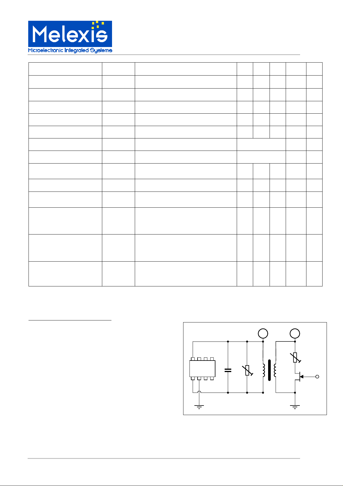
Test set up Block diagram
7
Modulation on the reader antenna is limited towards
maximum modulation depth, to prevent the reader from
VDD
going into power down.
Modudepth = (VPPmax-VPPmin)/( VPPmax+VPPmin)
Since Vppmin (Vmodu=4.2V)=1.6V,
and Vppmax (Vmodu=0.8V)=8.4, modudepthmax=68%.
8
The data slicer samples every 4 clock periods(=1/Fres),
8
7 6 5
90109
1 2 3 4
therefore any pulse on the output can be 4 periods off.
C
R
R
L
par
R
MLX90109 Parallel Resonant transceiver Page 3 of 9 Rev 1.4 19-Dec-00
VDD
L
tag
R
damp
Page 4

MLX90109
125kHz RFID Integrated Transceiver
General Description
The MLX90109 is designed for use with a parallel
antenna. This set up requires Qantenna times less
current compared to traditional serial antennas, for
building up the same magnetic field strength. Draw
back is that the voltage swing (Vpp) is limited by the
applied supply voltage.
Vppmax ~ 2* VDD.
In practice the antenna driver on the COIL pin limits
the voltage swing some more.
The MODU pin can regulate Vpp. The voltage level
on MODU defines the reference level of the antenna
voltage, as follows
Vpp ~ 2*(VDD-VMODU)
See specifications for VMODU values.
Oscillator
The oscillator frequency is locked on the antenna
frequency. The clock of the filter is derived from the
oscillator. In this way the filter characteristics are
locked to the transmission frequency. Consequently
the MLX90109 is not sensitive to zero modulation.
Amplitude detection
The amplitude demodulator of the transceiver detects
the AM signal generated by the tag. This signal is
filtered and amplified by an on-chip switched capacitor
filter before feeding it to the digital decoder. The
same signal is used to control the antenna voltage.
Filter settings
By setting the SPEED pin to VDD or to GND the
filtering characteristics are optimized for either 2kbaud
or 4kbaud respectively.
Digital decoding
The MODE pin allows to define whether to issue
directly the filtered data stream on the DATA pin
(MODE floating), or to have the MLX90109 decoding
Manchester (MODE = VDD) or biphase (MODE =
VSS) data.
In the decoding mode, the digital receiver gets the
filtered data stream and issues the tag data on the
DATA pin at the rising edge of the clock, which is
issued on the CLOCK pin. Both CLOCK and DATA
are open drain outputs and require external pull-ups.
Remark that the clockwidth and duty cycle can vary
from bit to bit, between a half and one and a half bit
periods on the tag coil especially in manchester mode.
Power Down
By setting V
0. At that moment MLX90109 stops oscillations,
setting the device in power down mode. Wake up
time depends on Qantenna, such that increased Q,
will lead to increased wake up time.
= VDD, Antenna Voltage will fade to
MODU
Write operation
Not only is the MODU pin used to set the carrier
amplitude, it can also be used to put modulation on
the carrier for write operations.
Taking into account the transfer function of the
regulation mechanism, a correction network is
required to compensate for the system poles and
zeroes. These poles and zero depend not only on
internal parameters, but also on the antenna
parameters.
See annex for calculating the correction network.
VSS FLOAT (*) VDD
SPEED
MODE
(*) Internally strapped to VDD/2
4kBaud - 2kBaud
Biphase No decoding Manchester
Noise cancellation
Capacitance C2 should always be connected to VDD.
Noise on VDD is coupled through to MODU,
optimizing the power supply rejection ration (PSRR)
through internal cancellation. This improves
sensitivity in noisy environments. Maximum
precautions should however be taken to minimize
noise level, to benefit from the reader sensitivity, and
obtain the maximum reading distances.
MLX90109 Parallel Resonant transceiver Page 4 of 9 Rev 1.4 19-Dec-00
Page 5

MLX90109
125kHz RFID Integrated Transceiver
Correction network
For a typical application, where 2kbaud date has to
be sent to a transponder using a Manchester or
Biphase encoding scheme, the most important
harmonics lie in a bandwidth between 400Hz and
3.6kHz.
As can be seen from the graphs below, the antenna
parameters can significantly reduce the available
bandwidth [FL, FH].
With a suitable correction network, the 3dB points
can be shifted to extend the possibilities.
Important system parameters are data rate, antenna
inductance (Lreader) and antenna quality factor
(Qreader).
In the time domain we optimize the shape of the
amplitude modulation on the reader antenna by
applying that correction network.
dB(Vampl/Vmodu)
MLX90109
Calculation
In the graph below the transfer function of the
MLX90109 is given.
• The first Zero (Fi) is determined the by the
MLX90109 and is typically 70Hz.
• The Poles (FL and FH) are set by the Open loop
Gain (G=2mA/V) of the MLX90109 and the
Antenna Impedance Zant, which is system
dependent. In the graphs below the
dependency of both poles on applied inductance
and for 2 quality factors are reflected. It is clear
that the bandwidth reduces significantly with
increase of Qreader.
Remark: Amax = G*Zant
A correction network with a single pole/zero couple
can increase the bandwidth by moving FH to FHH.
A more complex correction network with 2 pole/zero
couples can also improve the signal loss in case of
important low frequency harmonics (DC like signals).
In the Frequency domain this means FL is shifted
towards Fi
FH -> F
A
max
0
0
-A
max
A
max
0
fif
L
Correction network with ... single pole/zero:
f
f
i
L
MLX90109 + different correction networks
f
f
i
L
... double pole/zero:
f
H
f
H
f
H
f
HH
f
HH
HH
FL -> F
i
Frequency Domain Time Domain
MLX90109 Parallel Resonant transceiver Page 5 of 9 Rev 1.4 19-Dec-00
Page 6

Bandwidth graphs
MLX90109
125kHz RFID Integrated Transceiver
2.5
2.0
1.5
Freq [kHz]
1.0
0.5
0
0
2.5
MLX90109
F
HH
F
H
Q = 30
F
L
60
40
20
80
100
120
140
L [uH]
2.5
2.0
1.5
Freq [kHz]
1.0
0.5
0
0
F
H
Q = 40
F
L
60
40
20
L [uH]
MLX90109
F
HH
2.5
80
MLX90109
100
120
MLX90109
140
2.0
1.5
Freq [kHz]
1.0
0.5
0
0
F
H
Q = 30
F
L
60
40
20
80
100
120
140
L [uH]
2.0
1.5
Freq [kHz]
1.0
0.5
0
0
F
H
Q = 40
F
L
60
40
20
80
100
120
140
L [uH]
MLX90109 Parallel Resonant transceiver Page 6 of 9 Rev 1.4 19-Dec-00
Page 7

Applications Information
MLX90109
125kHz RFID Integrated Transceiver
VDD
C2=68nF
uctrl
Read/
Write
C1=47nF
39k
100k47k
MLX90109 Read/Write demokit:
Above schematic is used in a demokit which
allows to
• read and write
• the MLX90111 with 2cm diameter aircoils
• at 2 and 4kbaud, using Manchester and
Biphase encoding
• up to 7cm
whilst consuming only 5mA, inlcuding antenna
current.
An Atmel microcontroller (AT90S8515) was used
to have enough ports to drive a ledbar.
Rpar
Rr, Lr, Cr
1 8
2
3
4
MLX
7
6
5
90109
MODE
SPEED
VDD
CD=100nF
DataIN
ClockIN
uctrl
100k
100k
The field of the coil is proportional to the number
of windings and to the current flowing through it:
H ~ N.I = N.V/(ω.L)
with V the ac voltage across the coil, and ω.L
the impedance of the coil.
Furthermore the inductance of the coil is
proportional to the square of the number of
windings.
L = Lo*N
2
Antenna parameters:
With Lo the inductance of 1 turn.
- Lr= 89uH, Cr= 18nF
- Qr=30
- Rpar= Optional parallel resistance
So
H ~ V/(ω.Lo.N)
Reducing the number of turns on the coil is good
for improving the field strength as well as for
Coil design considerations
Let's start from an operation frequency of 120
kHz. In order for the antenna not to get detuned
by stray capacitance to ground, it is good not to
have a high L value. In this way C is big and the
detuning is minimal.
making the construction of the coil easier.
Antenna impedance specification is determined
by the current that the antenna driver can
supply. Outside the specification, the feedback
loop will not operate as designed for, and
functionality will deteriorate drastically.
Zant = Zr // Rpar with Zr = Lr/(Rl*Cr)
MLX90109 Parallel Resonant transceiver Page 7 of 9 Rev 1.4 19-Dec-00
Page 8

MLX90109
125kHz RFID Integrated Transceiver
Unique Features
Use of a parallel antenna offers multiple
advantages:
- maximum power efficiency.
- minimum system components
Ease of use thanks to:
- self resonating principle avoids zero
modulation
- flexible system configuration with higher Q's
- High level of integration.
A complete reader can be integrated on an ultra
small PCB thanks to:
- small body (150mills) SOIC8 package
- limited amount of external components
- Integrated decoding minimize demands on
microcontroller side.
Cross Reference
The MLX90109 can replace any integrated frontend base station chip for read write operation to
125kHz transponders in the 125kHz range.
All competitive products are with serial antenna,
e.g. Marin p4092, or TEMIC U2270B.
Absolute Maximum Ratings
Supply Voltage, VDD (Overvoltage)
Storage Temperature Range, T
ESD Sensitivity 2kV
S
VSS-0.3V to
VSS+6V
[-55, 125]°C
ESD Precautions
Electronic semiconductor products are sensitive
to Electro Static Discharge (ESD).
Always observe Electro Static Discharge control
procedures whenever handling semiconductor
products.
Disclaimer
Melexis reserves the right to periodically make
modifications to product specifications. The
information included herein is believed to be
accurate and reliable. However, Melexis
assumes no responsibility for its use; nor for
any infringements of patents or other rights of
third parties which may result from its use.
Melexis
FAQ
1. Since the MLX90109 under the specified
working conditions does not influence the
antenna resonance frequency, the spread
and temperature drift are determined by the
discrete antenna components only.
2. The same feature allows significantly
detuned transponders to change the
resonance frequency in case of good
coupling. This can be used to tune the
MLX90111 after assembly, to allow use of
high Q factors at minimum assembly cost.
3. Q = quality factor of the antenna reflects the
ratio between the stored electromagnetic
energy vs. the ohmic dissipated energy.
Without degrading Rpar:
Qreader = (2*pi*Fres*Lr)/Rr
Else Rr can often be neglected resulting in:
Qreader = Rpar*sqrt(Cr/Lr)
4. Zero Modulation
Due to mistuning of the resonance
frequency of transponder and reader
antennas compared to an external oscillator
frequency, the amplitude modulation
induced by the transponder on the reader
antenna is a mixture of amplitude and phase
modulation. At special combinations of the
three frequencies a pure phase modulation,
or zero (amplitude) modulation occurs.
Since the MLX90109 clock is extracted from
the antenna resonance frequency it is not
susceptible to this phenomenon.
5. The MLX90109 is insensitive to DC
magnetic levels.
6. Modudepth = (VPPmax-VPPmin)/
(VPPmax+VPPmin)
Glossary of Terms
1. Base station = reader IC + microcontroller
2. Transceiver = Write (Transmitter) and read
(receiver) unit
3. Q = antenna quality factor.
4. Modulation depth = ratio between the
antenna amplitudes that are used for
sending data with amplitude modulation.
MLX90109 Parallel Resonant transceiver Page 8 of 9 Rev 1.4 19-Dec-00
Page 9

SO8 Pinout
Melexis is QS 9000/ VDA6.1 / ISO14000 Certified
Pin Name Function
1 COIL Antenna connection: pull down NMOSFET
2 VSS Ground
3 SPEED Digital input, strapped to VSS or VDD.
4 MODU Modulation input
5 MODE Digital input, strapped to VSS or VDD.
6 CLOCK Clock output
7 DATA Data output
8 VDD Supply
For the latest version of this document,
Go to our website at:
www.melexis.com
Or for additional information
contact Melexis Direct:
MLX90109
125kHz RFID Integrated Transceiver
1 8
MLX
90109
2
3
4
7
6
5
USA
Melexis Inc. 41 Locke Road, Concord, NH 03301
Phone: +1 603 223 2362 Fax: +1 603 223 9614 E-mail: sales_usa@melexis.com
United Kingdom
Silicon Concepts PCB Lynchborough Road, Hampshire GU30 7SB, United Kingdom
Phone: +44 1428 751 617 Fax: +44 1428 751 603 E-mail: sales_uk@melexis.com
Germany
Melexis/Thesys Am Seestern 8, 40547 Düsseldorf, Germany
Phone: +49 211 5360212 Fax: +49 211 5360250 E-mail: sales_de@melexis.com
France
Melexis France Tour Arago, 5 rue Bellini, 92806 Puteaux-La-Défense, France.
Phone: +33 1 47 78 11 34 Fax: +33 1 47 78 06 35 E-mail: sales_france@melexis.com
Italy
Dimacred IRL Via Papa Giovanni XXIII no. 25, 20046 Biassono, Italy
Phone: +39 039 249 4856 Fax: +39 039 491773 E-mail: sales_italy@melexis.com
Japan
Satori Electric Co., LTD 1-14-10 Shiba, Minato-Ku, Tokyo, Japan
Phone: +81 3 3452 7171 Fax: +81 3 3769 2197 E-mail: sales_japan@melexis.com
Taiwan
Beechwood Int’l Taiwan Co. Room 8, 17F, No. 189, Taipei, Taiwan
Phone: +886 2 2739 3322 Fax: +886 2 2739 3090 E-mail: sales_taiwan@melexis.com
MLX90109 Parallel Resonant transceiver Page 9 of 9 Rev 1.4 19-Dec-00
 Loading...