

Page 1

MLX10407
5-Channel Gauge Driver with Serial Link
Features and Benefits
Supply voltage up to 12 V
Interface directly with 5 V CMOS logic MCUs
Serial link
Can drive two 360° actuators & three 90° actuators simultaneously
Open circuit / short -circuit detection of the drivers outputs
Small size (SO24 package)
Real Time Angle Tracking
Applications
Logometer Driver Dashboard
Industrial Metering
Ordering Information
Part No. Temperature Suffix Package Temperature Range
MLX11407CA N/A SO24 -40C to +85C Automotive
Functional Diagram
Description
The 10407 is a MCU peripheral for logometers control using SIN/COS PWM commands. The circuit controls two
independent sets of CMOS power bridges. A ten-bit angle is displayed with a 9 bit per quadrant resolution PWM whose
frequency is set by a crystal oscillator. A power-on self test detects open or short-circuit outputs for each logometer and
a real time angle tracking avoids display errors.
The 10407 can also drive three small angle logometers (90°). A three wire serial link allows bidirectional communication
with the MCU.
MLX902xx Name of Sensor Rev Y.X 22/Aug/98 Page 1
MLX10407 5-Channel Gauge Driver with Serial Link Page 1 Rev 1.1 28/Apr/01
Page 2
MLX10407
5-Channel Gauge Driver with Serial Link
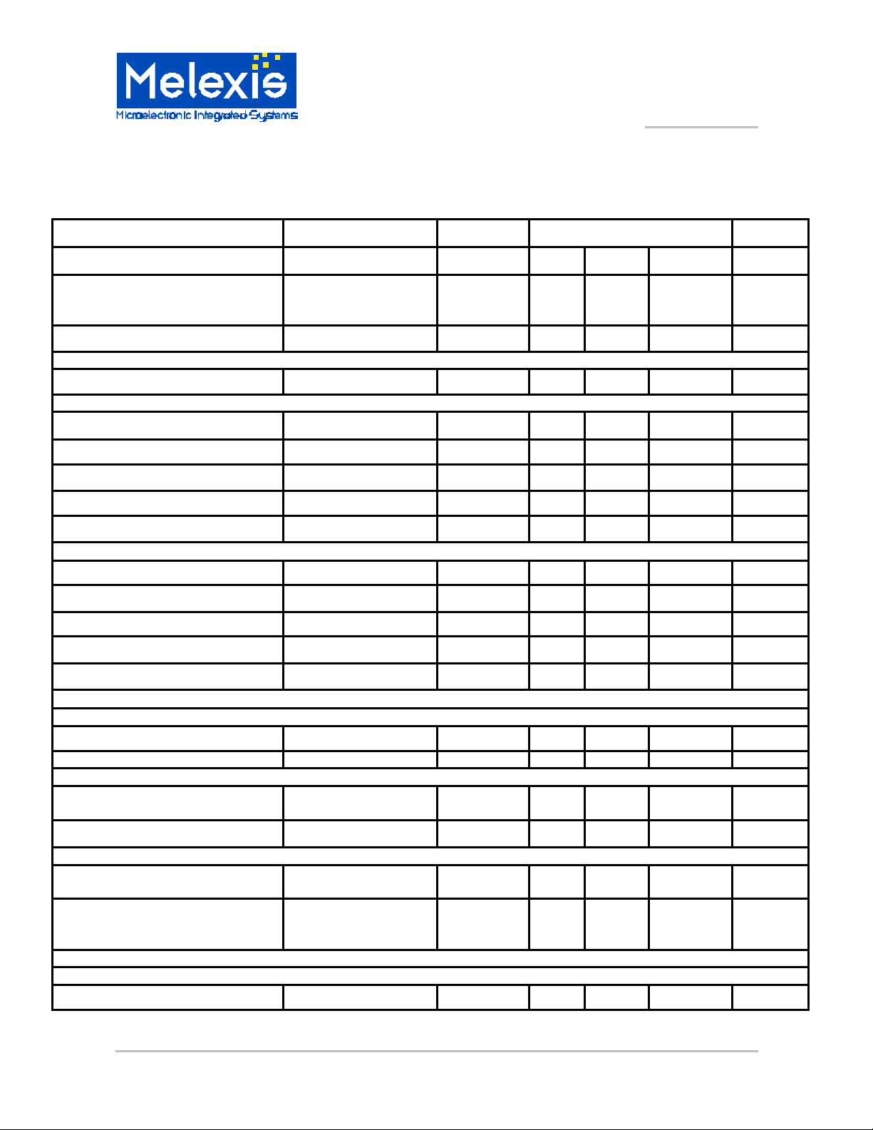
DC Electrical Characteristics
Tamb = -40 to 85°C, VDD = 4.5 V to 12 V unless otherwise specified.
Characteristics Test Conditions
Supply current Inputs at VDD or
VSS, No loads on
outputs
Maximum power dissipation
Inputs
Input capacitance
Pin 11
Pull-down resistance
Input voltage LOW
Input voltage HIGH
Hysteresis VDD = 8.5 V
Leakage current pin at VDD or VSS
Pin 12, 13, 14, 15, 17
Input voltage LOW
Input voltage HIGH
Hysteresis VDD = 8.5 V
Leakage current (pin 12, 15, 17) pin at VDD or VSS
Pull-down resistance (pin 14) Rpd 0.8 1.5 kOhm
Symbol Limits Unit
Min Typ Max
ICC
PDmax
Cin
Rpd 125
VIL -0.3
VIH 4
VHYS 0.5
IL -1
VIL -0.3
VIH 4
VHYS 0.5
IL -1
5.5 mA
620 mW
10 pF
750 kOhm
1 V
VDD+0.3 V
2.5 V
1 µA
1 V
VDD+0.3 V
2.5 V
1 µA
Outputs
Pin 16
Low level output voltage IOUT < 500 µA
High level output leakage current VOUT=VDD ILKG 10 µA
Pin 2, 3, 5, 6, 20, 21, 23, 24
Drop-out voltage for each pair of
buffers
Mismatch of drop -out voltage
Pin 7, 8, 9
Output voltage low VDD = 8.5V, Tamb=
Output voltage high VDD = 8.5V, Tamb=
Oscillator
Pin 18,19
Input pin capacitance
MLX10407 5-Channel Gauge Driver with Serial Link Page 2 Rev 1.1 27/Apr/01
VDD = 8.5V, Tamb =
25°C, Icoil = 30 mA
25°C, Isink = 40mA
25°C, Isource =
40mA
VOL
Vd
D Vd
VOL
VOH 6.8 7.8
Cin
0.3 V
1.6 V
± 50 mV
0.3 0.6 V
10 20 pF
V
Page 3
5-Channel Gauge Driver with Serial Link
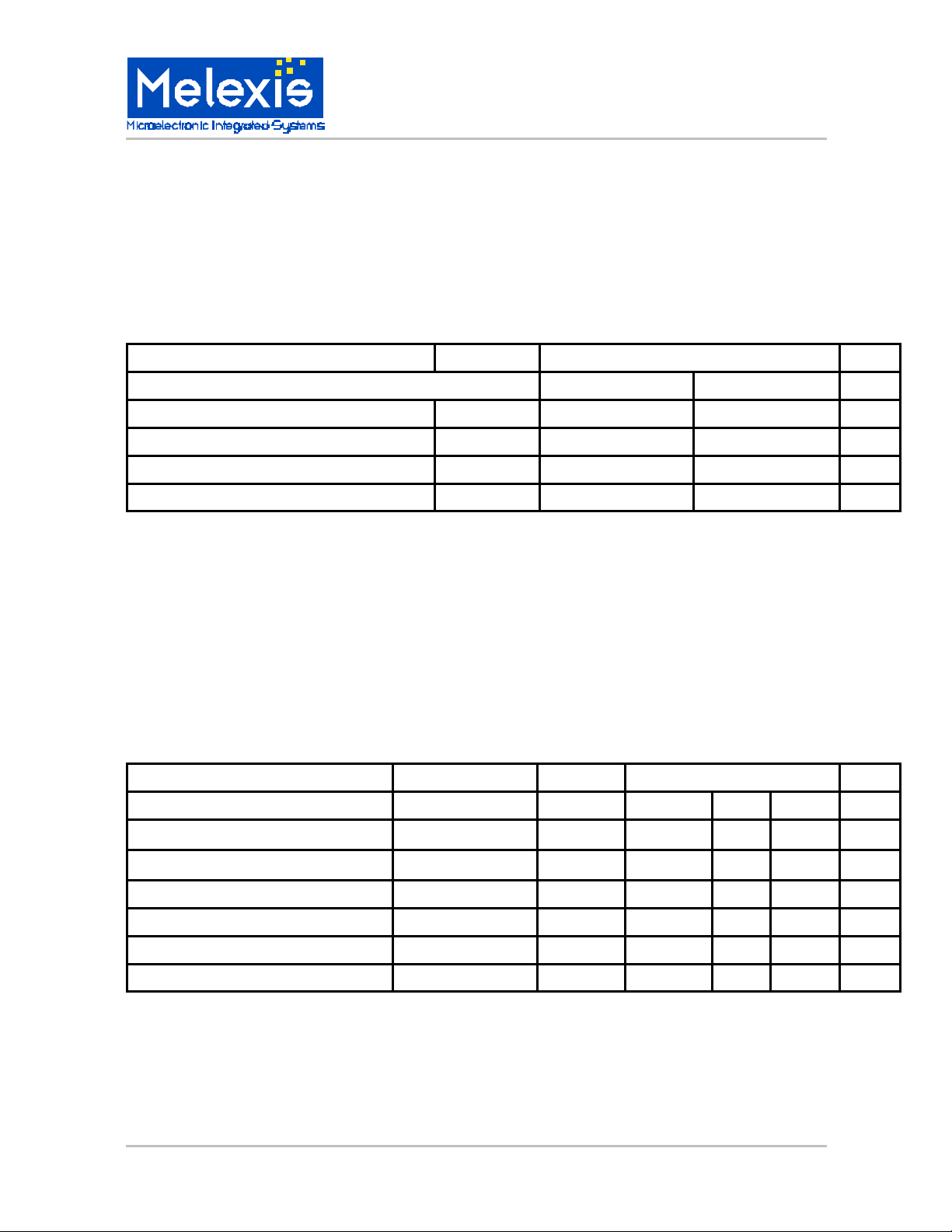
ABSOLUTE MAXIMUM RATINGS
MLX10407
Parameter Symbol
Min Max
Storage Temperature Range Tstg -40 +150 °C
Operating Temperature Range Tamb -40 +85 °C
Supply Voltage Range VDD -0.3 14.0 V
Input Voltage Range Vi -0.3 VDD +0.3 V
Value
AC Electrical Characteristics
Tamb = -40 to 85°C, VDD = 4.5 V to 12 V unless otherwise specified.
Characteristics Test Conditions
Symbol
Limits
Unit
Unit
Min Typ Max
Oscillator 0.95 8.4 MHz
Clock frequency Fclk 8 MHz
Serial communication
Serial data clock frequency Fsclk 500 kHz
Time for DIN stable to SCLK rise 100 ns
Hold time for DIN 100 ns
MLX902xx Name of Sensor Rev Y.X 22/Aug/98 Page 3
MLX10407 5-Channel Gauge Driver with Serial Link Page 3 Rev 1.1 28/Apr/01
Page 4

MLX10407
Typical application
5-Channel Gauge Driver with Serial Link
Notes
• The chip integrates its oscillator load capacitors.
• The quartz frequency is 8MHz
MLX10407 5-Channel Gauge Driver with Serial Link Page 4 Rev 1.1 27/Apr/01
Page 5

MLX10407
5-Channel Gauge Driver with Serial Link
Operation
1) 360° logometers
Immediately following a reset, the IC checks if there is any short -circuit or open circuit on each
buffer driver output (This test is not performed for outputs 5, 6 and 7). During this test, each buffer
is held in a high impedance state and large value internal resistors (100kOhm ) are sequentially
connected on each pair of buffers (note : actuator coils must be connected on bridges).
Three tests are performed according to the following figure and table.
Test for short and open circuits
Test 1 S1 closed, S2 open V1 = VSS
Test 2 S1 open, S2 closed V1 = VDD
Test 3 S1 and S2 closed V1 = VDD/2
During the tests the pin ERRB (16) is at logic level 0. After completing the tests, ERRB remains
low if one (or more) test failed.
ERRB returns to high impedance if everything is OK.
These tests last approximately 4 ms with an oscillator clock frequency of 8 MHz.
After testing, all buffers are at VSS. The chip then waits for the MCU to send an angle/quadrant
value to output the PWM signals for each buffer. Every logometer coil is connected in a bridge,
so the current Icoil can be either positive or negative.
Conditions Test for :
The total drop -out of a bridge is : Vd = | VCC - Vcoil |
One Bridge
MLX902xx Name of Sensor Rev Y.X 22/Aug/98 Page 5
MLX10407 5-Channel Gauge Driver with Serial Link Page 5 Rev 1.1 28/Apr/01
Page 6

MLX10407
5-Channel Gauge Driver with Serial Link
2) 90° logometers
In addition to driving (2) 360° logometers the MLX10407 has a push-pull stage so it Is possible to
drive (3) additional 90° coils connected to GND or VDD respectively.
Serial Link
The MCU outputs the serial communication clock SCLK, the chip select CS, the data DIP, and
reads the ERRB error stat us.
The data sent by the MCU is latched by the 10407 on the rising edge of SCLK.
The 10407 outputs the ERRB signal on the falling edge of SCLK
When CS = "0" the serial interface of the 10407 is inactive. When CS goes HIGH, the 10407
waits for a START BIT and then reads the following 15 bits transmitted by the MCU.
The START BIT (D0) must be "1".
D1 D2 D3 Instruction
0 0 0 Unused
0 0 1 Writing request LOGO1
0 1 0 Unused
0 1 1 Writing request LOGO2
1 0 0 Writing request LOGO3
1 0 1 Writing request LOGO5
1 1 0 Writing request LOGO4
1 1 1 Unused
The following 10 bits (D4, D5, D6, D7, D8, D9, D10, D11, D12, D13) set the angle value (D13
=lsb, D4 = msb).
The two remaining bits (D14D15) represent the quadrant (D14=msb). Note: for Logo1 & 2 only.
MLX10407 5-Channel Gauge Driver with Serial Link Page 6 Rev 1.1 27/Apr/01
Page 7

Serial Link
Sclk
CS
Din
ERRB
HiZ
MLX10407
5-Channel Gauge Driver with Serial Link
10 Bit AngleCODOP
MLX10407 Serial link Protocol
Quad
Error
The 10407 outputs an error status on pin ERRB on the falling edge of SCLK immediately
following the transmission of the quadrant lsb.
The pin 16 (ERRB) of the 10407 is driven low if there is no continuity between two consecutive
quadrant values sent (for logo1 or logo2). The data is valid till CS is high, then when CS goes low
ERRB returns to high impedance state and the error status is lost.
If the MCU has detected an error, it is possible to send data again : the first data bit set to "1" will
initiate a new transmission of 15 data bits.
On the HIGH to LOW transition of CS the angle and quadrant values are stored into the intern al
registers of the 10407 if the following conditions are met:
• The MCU sent the appropriate writing request
• No quadrant err or was detected by the 10407.
Otherwise new angle and quadrant values are discarded by the 10407 and the previous values
are kept. The MCU will have to initialize a new transmission to the 10407.
If VER (pin 17) is connected to VDD then the 10407 does not store values of angles and
quadrant in case of an error. It is however possible to make the 10407 store all angles and
quadrant values even if there is an error, by connecting VER (pin 17) to GND.
MLX902xx Name of Sensor Rev Y.X 22/Aug/98 Page 7
MLX10407 5-Channel Gauge Driver with Serial Link Page 7 Rev 1.1 28/Apr/01
Page 8

MLX10407
5-Channel Gauge Driver with Serial Link
PWM Generation
1) Logometers 360° ( Logo 1 and Logo 2 ):
From the angle value received from the MCU (range [0° - 89.8°]), the 10407 generates two PWM
signals (9 bit resolution) :
• The first one represents the sine PWMSIN,
• The second one is the cosine PWMCOS.
The 10407 uses a 512x9 ROM containing the sine of all angular values in the range [0° -89.8°]
(note that the lsb value of the angle is not used).
An angle value greater than 90° is obtained using different quadrant values :
• Q1 (D14D15 = 00) > 0° =< a < 90°
• Q2 (D14D15 = 01) > 90° =< a < 180°
• Q3 (D14D15 = 10) > 180° =< a < 270°
• Q4 (D14D15 = 11) > 270° =< a < 360°
a is the angle value
The PWM are switched to the outputs depending on the value of the quadrant :
• Logometer 1 is driven by outputs SIN1M/P COS1M/P,
• Logometer 2 is driven by outputs SIN2M/P COS2M/P.
The PWM frequency is given by :
F
= F
PWM
/ 512 (F
OSC
QUADRANT SIN1M SIN1P COS1M COS1P
D14 D15
0
0
1
1
= Crystal oscillator frequency)
OSC
0
1
0
1
0 PWMSIN 0 PWMCOS
0 PWMCOS PWMSIN 0
PWMSIN 0 PWMCOS 0
PWMCOS 0 0 PWMSIN
2) Logometers 90°
• There are three separate PWM outputs for Logo 3, Logo 4 and Logo 5.
MLX10407 5-Channel Gauge Driver with Serial Link Page 8 Rev 1.1 27/Apr/01
Page 9

Pin Out
5-Channel Gauge Driver with Serial Link
Pin Symbol Description
1 VDD
2 SIN1P Output buffer (coil 1 Logo1)
3 SIN1M Output buffer (coil 1 Logo1)
4 VSS
5 COS1P Output buffer (coil 2 Logo1)
6 COS1M Output buffer (coil 2 Logo1)
7 OUT5 Output buffer (Logo 3)
8 OUT6 Output buffer (Logo 4)
9 OUT7 Output buffer (Logo 5)
10 VDD
11 CS
12 SCLK Serial clock (Schmitt trigger)
13 DIN Data IN (Schmitt trigger)
14 TEST TEST input.(1K pull-down)
15 RSTB External reset (Schmitt trigger)
16 ERRB Quadrant error output (Open drain)
17 VER Quadrant verification inhibit
18 OSCO Crystal oscillator output
19 OSCI Crystal oscillator input
20 COS2M Output buffer (coil 2 Logo2)
21 COS2P Output buffer (coil 2 Logo2)
22 VSS
23 SIN2M Output buffer (coil 1 Logo2)
24 SIN2P Output buffer (coil 1 Logo2)
Chip select (Schmitt trigger with 300kOhm
pull-down)
MLX10407
For the latest version of this document,
Go to our website at:
www.melexis.com
Or for additional information
contact Melexis Di rect:
USA
Melexis Inc.
41 Locke Road, Concord, NH 03301
Phone: +1 603 223 2362 Fax: +1 603 223 9614
E-mail: sales_usa@melexis.com
United Kingdom
Silicon Concepts
PCB Lynchborough Road, Hampshire GU30 7SB, United Kingdom
Phone: +44 1428 751 617 Fax: +44 1428 751 603
E-mail: sales_uk@melexis.com
Germany
Am Seestern 8, 40547 Düsseldorf, Germany
Phone: +49 211 5360212 Fax: +49 211 5360250
E-mail: sales_de@melexis.com
MLX902xx Name of Sensor Rev Y.X 22/Aug/98 Page 9
MLX10407 5-Channel Gauge Driver with Serial Link Page 9 Rev 1.1 28/Apr/01
France
Melexis France
Tour Arago, 5 rue Bellini, 92806 Puteaux-La-Défense, France.
Phone: +33 1 47 78 11 34 Fax: +33 1 47 78 06 35
E-mail: sales_france@melexis.com
Italy
Dimacred IRL
Via Papa Giovanni XXIII no. 25, 20046 Biassono, Italy
Phone: +39 039 249 4856 Fax: +39 039 491773
E-mail: sales_italy@melexis.com
Japan
Satori Electric Co., LTD
1-14-10 Shiba, Minato -Ku, Tokyo, Japan
Phone: +81 3 3452 7171 Fax: +81 3 3769 2197
E-mail: sales_japan@melexis.com
Taiwan
Beechwood Int’l Taiwan Co.
Room 8, 17F, No. 189, Taipei, Taiwan
Phone: +886 2 2739 3322 Fax: +886 2 2739 3090
E-mail: sales_taiwan@melexis.com
 Loading...