

Page 1
MKP 338 2 X2
168x12(halfpage)
Vishay BCcomponents
Interference Suppression Film Capacitors
168x12(halfpage)
l
h
P
w
l
t
Ø d
F'
F
t
10
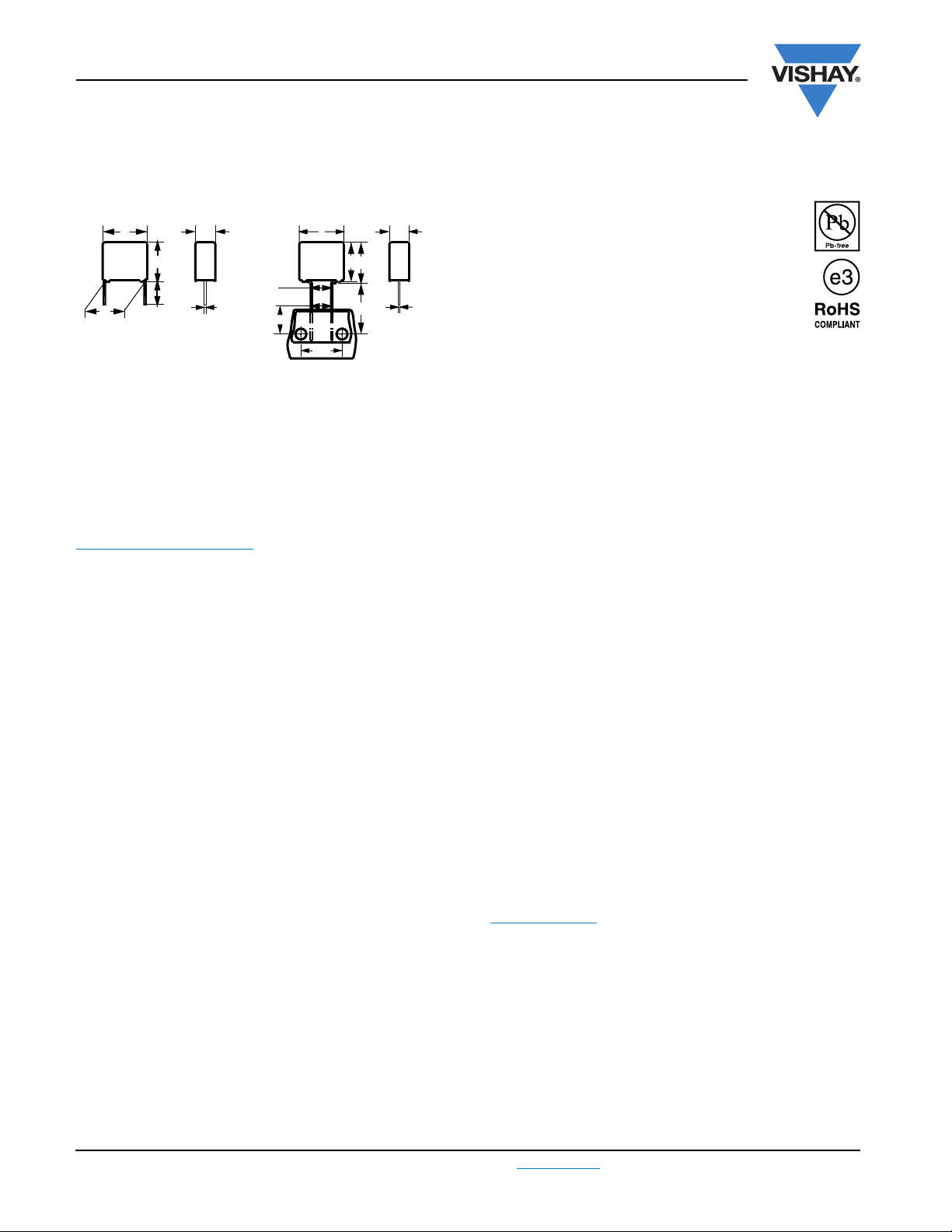
MKP Radial Potted Type
FEATURES
l
h
(1)
15
w
h'
7.5 mm to 27.5 mm lead pitch. Supplied in box,
taped on ammopack or reel.
Compliant to RoHS directive 2002/95/EC.
H
Ø d
t
PERMISSIBLE DC VOLTAGE
DC 630 V
Dimensions in mm
⎪F − F"⎪<0.3 mm
F = 7.5 + 0.6/- 0.1 mm
APPLICATIONS
For standard across the line X2 applications
See also application note:
www.vishay.com/doc?28153
REFERENCE STANDARDS
“IEC 60384-14 ed 3 and EN 60384-14”
“IEC 60065 requires pass flamm class B”
UL1414; CSA-C22.2 No. 1
UL1283; CSA-E384-14, CQC
MARKING
C-value; tolerance; rated voltage; sub-class; manufacturer’s
type designation; code for dielectric material, manufacturer
location; manufacturer’s logo; year and week; safety
approvals
DIELECTRIC
Polypropylene film
ENCAPSULATION
Plastic case, epoxy resin sealed, flame retardant UL-class
94 V-0
CLIMATIC TESTING CLASS ACC. TO IEC 60068-1
55/110/56/B
CAPACITANCE RANGE (E12 SERIES)
E12 series 0.001 µF to 3.3 µF
Preferred values acc. to E6
CAPACITANCE TOLERANCE
± 20 %; ± 10 %; ± 5 %
LEADS
Tinned wire
MAXIMUM APPLICATION TEMPERATURE
C ≤ 470 nF: 110 °C (125 °C for less than 1000 h)
C > 470 nF: 110 °C
ELECTRODES
Metallized film
CONSTRUCTION
Mono construction
RATED VOLTAGE
AC 310 V; 50 Hz to 60 Hz
www.vishay.com For technical questions, contact: rfi@vishay.com
145 Revision: 16-Jul-09
DETAIL SPECIFICATION
For more detailed data and test requirements contact:
RFI@vishay.com
Document Number: 28119
Page 2
MKP 338 2 X2
Interference Suppression Film Capacitors
Vishay BCcomponents
MKP Radial Potted Type
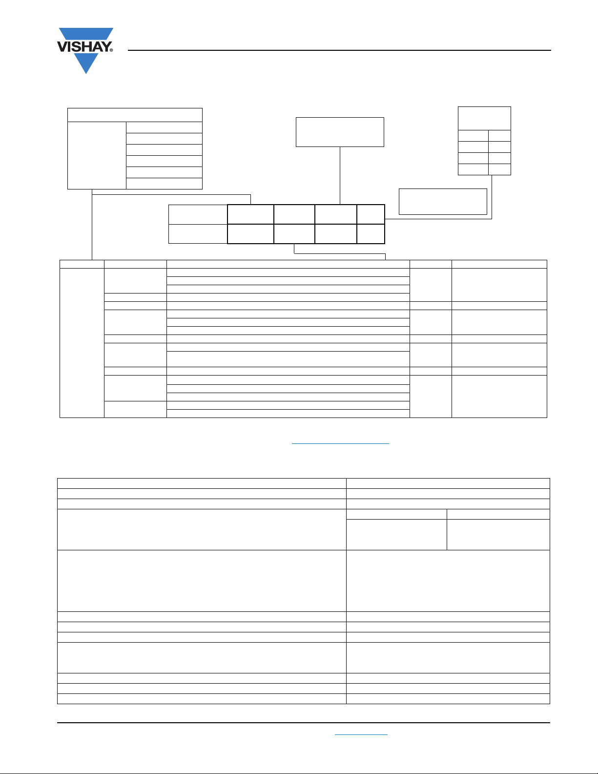
COMPOSITION OF CATALOG NUMBER
TYPE AND PITCHES
7.5 mm (bent back)
338 2
X2
7.5 mm
10.0 mm
15.0 mm
22.5 mm
27.5 mm
CAPACITANCE
(numerically)
Example:
104 = 10 x 10 = 100 nF
MULTIPLIER
(nF)
0.1 2
13
10 4
100 5
BFC2 338 2X XX X
2222
(*) Old ordering code
TYPE PACKAGING STANDARD DIMENSIONS C-TOL. PREFERRED TYPES
Loose in box
(2)
Taped
PACKAGING ALTERNATIVE LARGER PITCH SIZES C-TOL. ON REQUEST
Loose in box
338 2 X2
Notes
(1)
Taped on reel pitch = 27.5 mm is not available
(2)
For detailed tape specifications refer to “Packaging Information” www.vishay.com/doc?28139 or end of catalog
(3)
SPQ = Standard Packaging Quantity
PACKAGING ALTERNATIVE TAPED VERSION
(2)
Taped
PACKAGING ALTERNATIVE C-TOL ON REQUEST
Loose in box
(2)
Taped
Lead length 3.5 mm + 1 mm/- 0.5 mm or 3.5 mm ± 0.3 mm
Lead length 5.0 mm ± 1.0 mm BFC2 338 22...
Lead length 25.0 mm ± 2.0 mm BFC2 338 24...
Pitch 7.5 mm or bent back to 7.5 mm BFC2 338 26...
Lead length 3.5 mm + 1 mm/- 0.5 mm or 3.5 mm ± 0.3 mm
Lead length 25.0 mm ± 2.0 mm
Ammopack: H = 18.5 mm; P0= 12.7 mm ± 5 %
Reel: Pitch 7.5 mm (bent back) H = 16.0 mm; P
Lead length 3.5 mm + 1 mm/- 0.5 mm or 3.5 mm ± 0.3 mm
Lead length 5.0 mm ± 1.0 mm
Lead length 25.0 mm ± 2.0 mm See tables for details
Pitch 7.5 mm or bent back to 7.5 mm
H = 18.5 mm; P
(*)
338 2X XX X
=12.7mm
0
(1)
= 15.0 mm
0
± 20 %
± 20 % See tables for detailsLead length 5.0 mm ± 1.0 mm
± 10 %
± 20 %
± 10 %
± 5 %
BFC2 338 20...
ON REQUEST
See tables for details
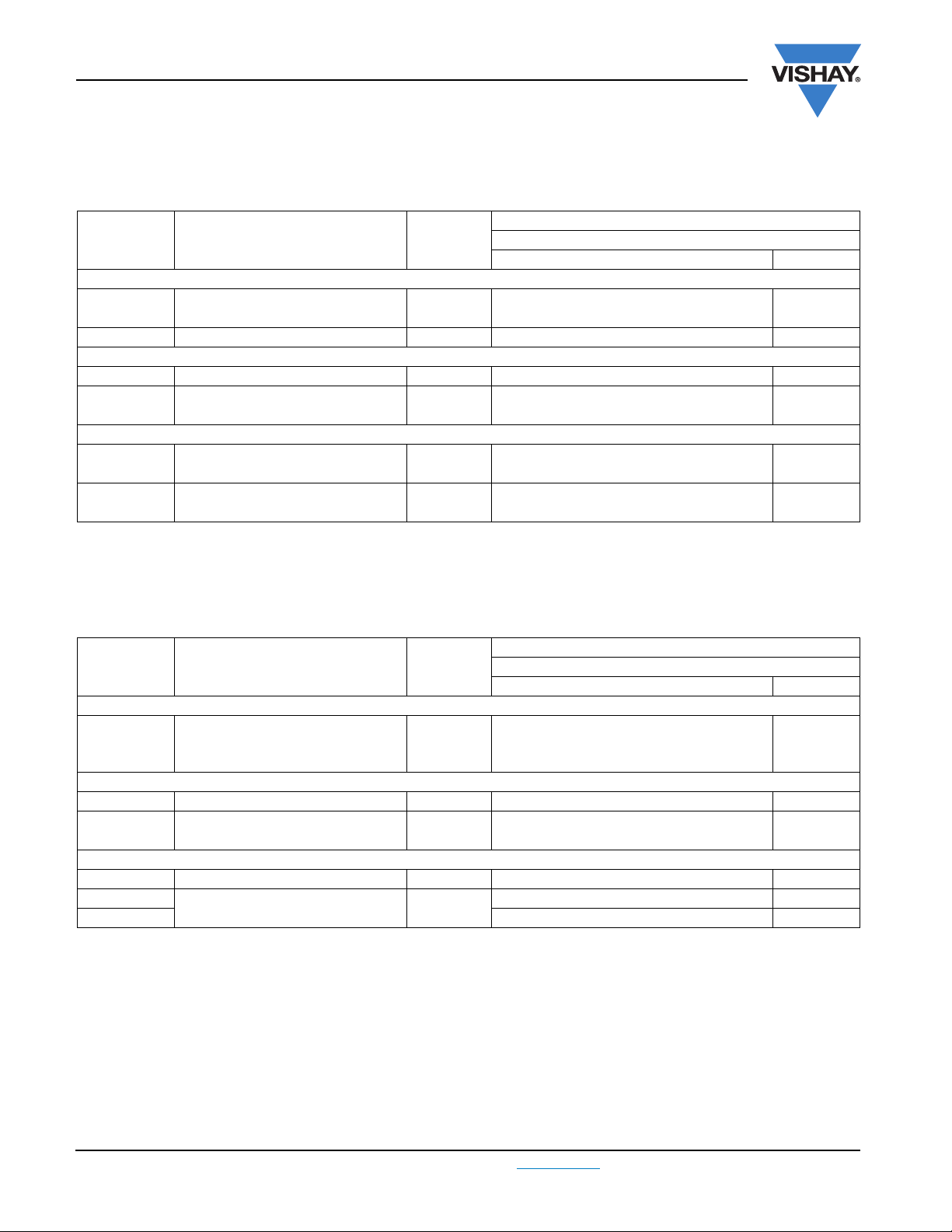
SPECIFIC REFERENCE DATA
DESCRIPTION VALUE
Rated AC voltage (U
Permisssible DC voltage (U
Tangent of loss angle: at 1 kHz at 10 kHz
C ≤ 470 nF ≤ 10 x 10
470 nF < C ≤ 1µF ≤ 20 x 10
C>1µF ≤ 30 x 10
Rated voltage pulse slope (dU/dt)
Pitch = 7.5 mm 600 V/µs
Pitch = 10 mm 600 V/µs
Pitch = 15 mm and 7.5 mm (bent back) 400 V/µs
Pitch = 22.5 mm 150 V/µs
Pitch = 27.5 mm 100 V/µs
R between leads, for C ≤ 0.33 µF at 100 V; 1 min > 15 000 MΩ
RC between leads, for C > 0.33 µF at 100 V; 1 min > 5000 s
R between leads and case; 100 V; 1 min > 30 000 MΩ
Withstanding (DC) voltage (cut off current 10 mA); rise time 100 V/s:
C ≤ 1µF 2200 V; 1 min
C>1µF 1800 V; 1 min
Withstanding (AC) voltage between leads and case 2120 V; 1 min
Max. application temperature for 0.001 µF ≤ C ≤ 0.47 µF 110 °C (125 °C for less than 1000 h)
Max. application temperature for C > 0.47 µF 110 °C
Document Number: 28119 For technical questions, contact: rfi@vishay.com
Revision: 16-Jul-09 146
) 310 V
Rac
) 630 V
Rdc
-4
-4
-4
at 435 Vdc
R
≤ 20 x 10
≤ 70 x 10
-4
-4
-
www.vishay.com
Page 3
MKP 338 2 X2
Vishay BCcomponents
Interference Suppression Film Capacitors
MKP Radial Potted Type
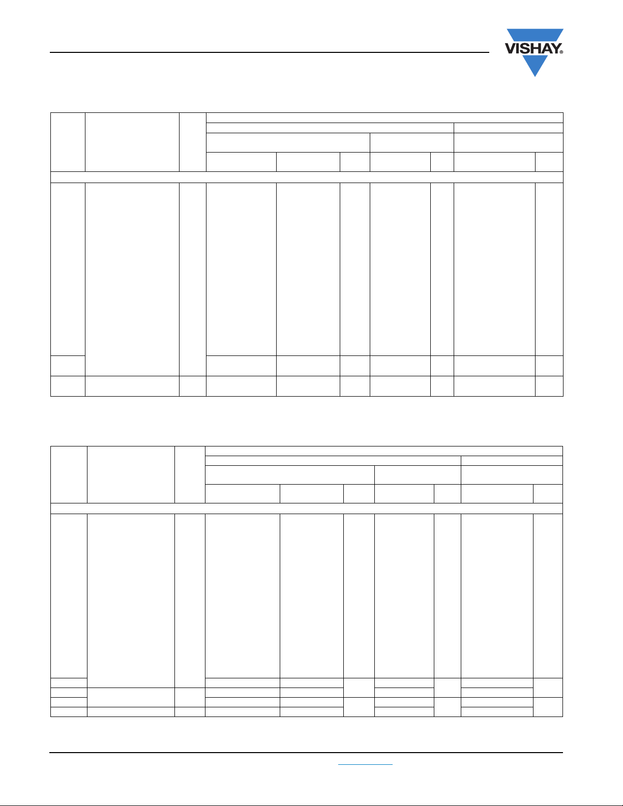
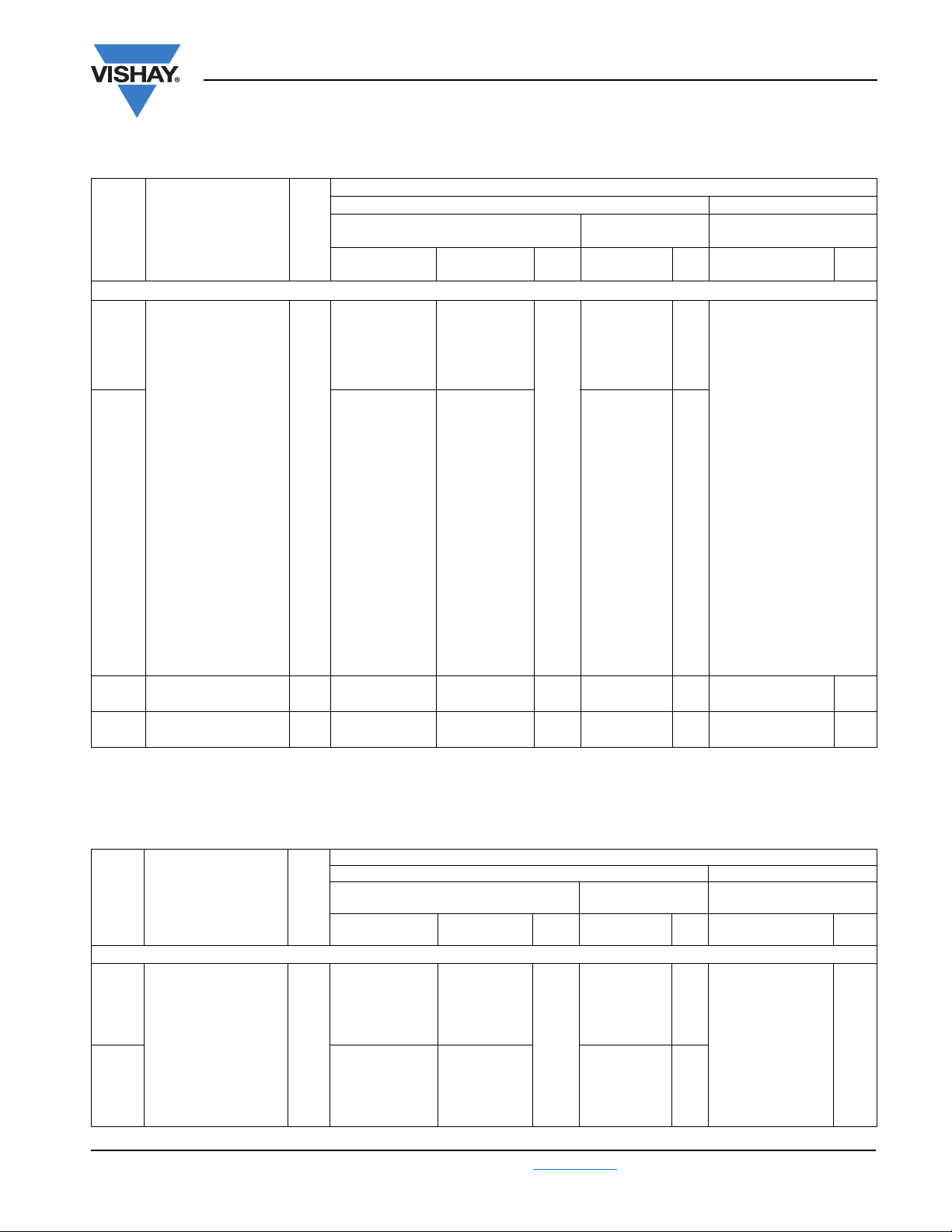
Pitch: 7.5 mm; C-tol. = ± 20 %
CATALOG NUMBER BFC2 338 ..... AND PACKAGING
C
(µF)
Pitch = 7.5 mm ± 0.4 mm; d
0.001
DIMENSIONS
w x h x l
(mm)
MASS
(2)
(g)
l
= 3.5 mm
t
+ 1 mm/- 0.5 mm
= 0.50 mm ± 0.05 mm
t
20102 22102
Short leads Long leads
0.0012 20122 22122 24122 26122
0.0015 20152 22152 24152 26152
0.0018 20182 22182 24182 26182
0.0022 20222 22222 24222 26222
0.0027 20272 22272 24272 26272
0.0033 20332 22332 24332 26332
0.0039 20392 22392 24392 26392
0.0047 20472 22472 24472 26472
0.0056 20562 22562 24562 26562
4.0x9.0x10.0 0.4
0.0068 20682 22682 24682 26682
0.0082 20822 22822 24822 26822
0.01 20103 22103 24103 26103
0.012 20123 22123 24123 26123
0.015 20153 22153 24153 26153
0.018 20183 22183 24183 26183
0.022 20223 22223 24223 26223
0.027 20273 22273
0.033 20333 22333 24333 26333
0.039
0.047 20473 22473 24473 26473
Notes
(1)
H = In-tape height, P0 = Sprocket hole distance; for detailed specifications refer to packaging information
(2)
Weight for short lead product only
5.0 x 10.5 x 10.0 0.6
20393 22393
LOOSE IN BOX AMMOPACK
lt= 5.0 mm
± 1.0 mm
SPQ
lt = 25.0 mm
± 2.0 mm
SPQ SPQ
24102
1500
1000
750
24273
24393
1000
1250
1000
H = 18.5 mm
P
= 12.7 mm
0
26102
26273
26393
(1)
1250
1000
750
Pitch: 7.5 mm; C-tol. = ± 10 %
CATALOG NUMBER BFC2 338 ..... AND PACKAGING
C
(µF)
DIMENSIONS
w xh xl
(mm)
Pitch = 7.5 mm ± 0.4 mm; d
0.001
MASS
(2)
(g)
= 0.50 mm ± 0.05 mm
t
= 3.5 mm
l
t
+ 1 mm/- 0.5 mm
28101 28301
Short leads Long leads
LOOSE IN BOX AMMOPACK
H = 18.5 mm
P
= 12.7 mm
lt= 5.0 mm
± 1.0 mm
SPQ
lt= 25.0 mm
± 2.0 mm
28501
SPQ SPQ
0
28701
0.0012 28102 28302 28502 28702
0.0015 28103 28303 28503 28703
0.0018 28104 28304 28504 28704
0.0022 28105 28305 28505 28705
0.0027 28106 28306 28506 28706
0.0033 28107 28307 28507 28707
0.0039 28108 28308 28508 28708
0.0047 28109 28309 28509 28709
0.0056 28111 28311 28511 28711
4.0 x 9.0 x 10.0 0.4
1500
1000
0.0068 28112 28312 28512 28712
0.0082 28113 28313 28513 28713
0.01 28114 28314 28514 28714
0.012 28115 28315 28515 28715
0.015 28116 28316 28516 28716
0.018 28117 28317 28517 28717
0.022 28118 28318 28518 28718
0.027 28119 28319
0.033
0.039 28122 28332
5.0 x 10.5 x 10.0 0.6
28121 28321 28521 28721
0.047 6.0 x 11.5 x 10.0 0.8 28123 28323 28523 28723
Notes
(1)
H = In-tape height, P0 = Sprocket hole distance; for detailed specifications refer to packaging information
(2)
Weight for short lead product only
1000
750
www.vishay.com For technical questions, contact: rfi@vishay.com
28519
28522
1250
1000
28719
28722
Document Number: 28119
147 Revision: 16-Jul-09
(1)
1250
1000
750
Page 4
MKP 338 2 X2
Interference Suppression Film Capacitors
Vishay BCcomponents
MKP Radial Potted Type
Pitch: 7.5 mm; C-tol. = ± 5 %
CATALOG NUMBER BFC2 338 ..... AND PACKAGING
C
(µF)
DIMENSIONS
w xh xl
(mm)
Pitch= 7.5mm ± 0.4mm; d
0.001
MASS
(2)
(g)
l
= 3.5 mm
t
+ 1 mm/- 0.5 mm
= 0.50 mm ± 0.05 mm
t
28201 28401
Short leads Long leads
(2)
LOOSE IN BOX AMMOPACK
H = 18.5 mm
P
= 12.7 mm
0
lt= 5.0 mm
± 1.0 mm
SPQ
l
= 25.0 mm
t
± 2.0 mm
28601
SPQ SPQ
28801
0.0012 28202 28402 28602 28802
0.0015 28203 28403 28603 28803
0.0018 28204 28404 28604 28804
0.0022 28205 28405 28605 28805
0.0027 28206 28406 28606 28806
0.0033 28207 28407 28607 28807
0.0039 28208 28408 28608 28808
0.0047 28209 28409 28609 28809
0.0056 28211 28411 28611 28811
4.0 x 9.0 x 10.0 0.4
1500
1000
0.0068 28212 28412 28612 28812
0.0082 28213 28413 28613 28813
0.01 28214 28414 28614 28814
0.012 28215 28415 28615 28815
0.015 28216 28416 28616 28816
0.018 28217 28417 28617 28817
0.022 28218 28418 28618 28818
0.027 28219 28419 1000 28619 1250 28819 1000
0.033
0.039 28222 28422 750 28622 1000 28822 750
5.0 x 10.5 x 10.0 0.6
28221 28421 1000 28621 1250 28821 1000
0.047 6.0 x 11.5 x 10.0 0.8 28223 28423 750 28623 1000 28823 750
Notes
(1)
H = In-tape height, P0 = Sprocket hole distance; for detailed specifications refer to packaging information
(2)
Weight for short lead product only
(1)
1250
Bent back pitch: 7.5 mm (only taped); C-tol. = ± 20 %
C
(µF)
Bent back pitch = 7.5 mm ± 0.4 mm; d
0.056
0.068 26683
0.082
0.1 26104
Bent back pitch = 7.5 mm ± 0.4 mm; d
DIMENSIONS
w x h x l
(mm)
= 0.60 mm ± 0.06 mm
t
5.0 x 13.0 x 12.5 0.82
6.0 x 14.0 x 12.5 1.1
= 0.60 mm ± 0.06 mm
t
MASS
(2)
(g)
0.12 5.0 x 13.0 x 17.5 1.0 26124 800
0.15
0.18 26184
Bent back pitch = 7.5 mm ± 0.4 mm; d
6.0 x 14.0 x 17.5 1.4
= 0.80 ± 0.08 mm
t
0.22 7.0 x 15.5 x 17.5 1.8 26224 550
0.27
0.33 26334 500
Notes
(1)
Reel diameter = 356 mm is available on request
(2)
Weight for short lead product only
8.5 x 17.0 x 17.5 2.4
Document Number: 28119 For technical questions, contact: rfi@vishay.com
Revision: 16-Jul-09 148
CATALOG NUMBER BFC2 338 ..... AND PACKAGING
REEL (500 mm)
(1)
H = 16.0 mm; P0 = 15.0 mm SPQ
26563
26823
26154
1600
1600
700
26274 550
www.vishay.com
Page 5
MKP 338 2 X2
Vishay BCcomponents
Interference Suppression Film Capacitors
MKP Radial Potted Type
Bent back pitch: 7.5 mm (only taped); C-tol. = ± 10 %
C
(µF)
Bent back pitch = 7.5 mm ± 0.4 mm; d
0.056
0.068 28725
DIMENSIONS
w x h x l
(mm)
= 0.60 mm ± 0.06 mm
t
5.0 x 13.0 x 12.5 0.82
MASS
(2)
(g)
0.082 6.0 x 14.0 x 12.5 1.1 28726 1600
Bent back pitch = 7.5 mm ± 0.4 mm; d
= 0.60 mm ± 0.06 mm
t
0.1 5.0 x 13.0 x 17.5 1.0 28727 800
0.12
0.15 28729
Bent back pitch = 7.5 mm ± 0.4 mm; d
0.18
0.22 28732
0.27
0.33 29168
Notes
(1)
Reel diameter = 356 mm is available on request
(2)
Weight for short lead product only
6.0 x 14.0 x 17.5 1.4
= 0.80 mm ± 0.08 mm
t
7.0 x 15.5 x 17.5 1.8
8.5 x 17.0 x 17.5 2.4
CATALOG NUMBER BFC2 338 .....AND PACKAGING
REEL (500 mm)
(1)
H = 16.0 mm; P0 = 15.0 mm SPQ
28724
28728
28731
28733
1600
700
550
500
Bent back pitch: 7.5 mm (only taped); C-tol. = ± 5 %
C
(µF)
DIMENSIONS
w x h x l
(mm)
Bent back pitch = 7.5 mm ± 0.4 mm; d
= 0.60 mm ± 0.06 mm
t
MASS
(2)
(g)
0.056
0.068
6.0 x 14.0 x 12.5 1.1
0.082
Bent back pitch = 7.5 mm ± 0.4 mm; d
= 0.60 mm ± 0.06 mm
t
0.1 5.0 x 13.0 x 17.5 1.0 28827 800
0.12
0.15 28829
Bent back pitch = 7.5 mm ± 0.4 mm; d
6.0 x 14.0 x 17.5 1.4
= 0.80 mm ± 0.08 mm
t
0.18 7.0 x 15.5 x 17.5 1.8 28831 550
0.22
0.27 28833 500
Notes
(1)
Reel diameter = 356 mm is available on request
(2)
Weight for short lead product only
8.5 x 17.0 x 17.5 2.4
CATALOG NUMBER BFC2 338 ..... AND PACKAGING
REEL (500 mm)
(1)
H = 16.0 mm; P0 = 15.0 mm SPQ
28824
28725
28726
28828
28832 550
1600
700
www.vishay.com For technical questions, contact: rfi@vishay.com
Document Number: 28119
149 Revision: 16-Jul-09
Page 6
MKP 338 2 X2
Interference Suppression Film Capacitors
Vishay BCcomponents
MKP Radial Potted Type
Pitch: 10.0 mm; C-tol. = ± 20 %
CATALOG NUMBER BFC2 338 ..... AND PACKAGING
LOOSE IN BOX AMMOPACK
lt= 5.0 mm
± 1.0 mm
SPQ
l
= 25.0 mm
t
± 2.0 mm
SPQ SPQ
25102
1250
1000
1000
750
750
24563
24823
750
750
27563
27823
C
(µF)
DIMENSIONS
w x h x l
(mm)
MASS
(2)
(g)
= 3.5 mm
l
t
Short leads Long leads
+ 1 mm/- 0.5 mm
Pitch = 10.0 mm ± 0.4 mm; d
0.001
= 0.60 mm ± 0.06 mm
t
21102 23102
0.0012 21122 23122 25122
0.0015 21152 23152 25152
0.0018 21182 23182 25182
0.0022 21222 23222 25222
0.0027 21272 23272 25272
0.0033 21332 23332 25332
0.0039 21392 23392 25392
0.0047 21472 23472 25472
0.0056 21562 23562 25562
0.0068 21682 23682 25682
4.0 x 10.0 x 12.5 0.6
0.0082 21822 23822 25822
0.01 21103 23103 25103
0.012 21123 23123 25123
0.015 21153 23153 25153
0.018 21183 23183 25183
0.022 21223 23223 25223
0.027 21273 23273 25273
0.033 21333 23333 25333
0.039 21393 23393 25393
0.047 21473 23473 25473
0.056
0.068 20683 22683 24683 27683
0.082
0.1 20104 22104 24104 27104
Notes
(1)
H = In-tape height, P0 = Sprocket hole distance; for detailed specifications refer to packaging information
(2)
Weight for short lead product only
5.0 x 11.0 x 12.5 0.82
6.0 x 12.0 x 12.5 1.1
20563 22563
20823 22823
H = 18.5 mm
P
= 12.7 mm
0
Not available
(1)
500
500
Pitch: 10.0 mm; C-tol. = ± 10 %
CATALOG NUMBER BFC2 338 ..... AND PACKAGING
C
(µF)
DIMENSIONS
w x h x l
(mm)
Pitch = 10.0 mm ± 0.4 mm; d
0.001
MASS
(2)
(g)
= 3.5 mm
l
t
+ 1 mm/- 0.5 mm
= 0.60 mm ± 0.06 mm
t
29194 29217
Short leads Long leads
LOOSE IN BOX AMMOPACK
H = 18.5 mm
P
= 12.7 mm
lt = 5.0 mm
± 1.0 mm
SPQ
l
= 25.0 mm
t
± 2.0 mm
SPQ SPQ
0
29241
0.0012 29195 29218 29242
0.0015 29196 29219 29243
1250
0.0018 29197 29221 29244
0.0022 29198 29222 29245
0.0027 29199 29223 29246
4.0 x 10.0 x 12.5 0.6
1000
Not available
0.0033 29201 29224 29247
0.0039 29202 29225 29248
1000
0.0047 29203 29226 29249
0.0056 29204 29227 29251
Document Number: 28119 For technical questions, contact: rfi@vishay.com
Revision: 16-Jul-09 150
(1)
www.vishay.com
Page 7

MKP 338 2 X2
Vishay BCcomponents
Interference Suppression Film Capacitors
MKP Radial Potted Type
Pitch: 10.0 mm; C-tol. = ± 10 %
CATALOG NUMBER BFC2 338 ..... AND PACKAGING
LOOSE IN BOX AMMOPACK
H = 18.5 mm
P
= 12.7 mm
lt = 5.0 mm
± 1.0 mm
SPQ
l
= 25.0 mm
t
± 2.0 mm
SPQ SPQ
0
C
(µF)
DIMENSIONS
w x h x l
(mm)
MASS
(2)
(g)
= 3.5 mm
l
t
+ 1 mm/- 0.5 mm
Short leads Long leads
0.0068 29205 29228 29252
0.0082 29206 29229 29253
0.01 29207 29231 29254
0.012 29208 29232 29255
0.015 29209 29233 29256
0.018 4.0 x 10.0 x 12.5 0.6 29211 29234 1000 29257 1000 Not available
0.022 29212 29235 29258
0.027 29213 29236 29259
0.033 29214 29237 29261
0.039 29215 29238 29262
0.047 29216 29239 29263
0.056
0.068 28125 28325 28525 28925
5.0 x 11.0 x 12.5
0.82 28124 28324 750 28524 750 28924 500
0.082 6.0 x 12.0 x 12.5 1.1 28126 28326 750 28526 750 28926 500
Notes
(1)
H = In-tape height, P0 = Sprocket hole distance; for detailed specifications refer to packaging information
(2)
Weight for short lead product only
(1)
Pitch: 10.0 mm; C-tol. = ± 5 %
CATALOG NUMBER BFC2 338 ..... AND PACKAGING
C
(µF)
DIMENSIONS
w x h x l
(mm)
Pitch = 10.0 mm ± 0.4 mm; d
MASS
(2)
(g)
l
= 3.5 mm
t
+ 1 mm/- 0.5 mm
= 0.60 mm ± 0.06 mm
t
LOOSE IN BOX AMMOPACK
Short leads Long leads
lt= 5.0 mm
± 1.0 mm
SPQ
l
= 25.0 mm
t
± 2.0 mm
H = 18.5 mm
P
= 12.7 mm
0
SPQ SPQ
(1)
0.056 5.0 x 11.0 x 12.5 0.82 28224 28424 750 28624 750 28944 500
0.068
0.082 28226 28426 28626 28946
Notes
(1)
H = In-tape height, P0 = Sprocket hole distance; for detailed specifications refer to packaging information
(2)
Weight for short lead product only
6.0 x 12.0 x 12.5 1.1
28225 28425
750
28625
750
28945
Pitch: 15.0 mm; C-tol. = ± 20 %
CATALOG NUMBER BFC2 338 ..... AND PACKAGING
C
(µF)
DIMENSIONS
w x h x l
(mm)
Pitch = 15 mm ± 0.4 mm; d
0.01
MASS
(3)
(g)
= 3.5 mm
l
t
± 0.3 mm
= 0.60 mm ± 0.06 mm
t
Short leads Long leads
29076 29096
LOOSE IN BOX REEL (500 mm)
H = 18.5 mm
P
= 12.7 mm
lt= 5.0 mm
± 1.0 mm
SPQ
l
= 25.0 mm
t
± 2.0 mm
29116
SPQ SPQ
0
29141
0.012 29077 29097 29117 29143
0.015 29078 29098 29118 29145
0.018 29079 29099 29119 29147
0.022 29081 29101 29121 29149
5.0 x 11.0 x 17.5 1.0
1000
1000
0.027 29082 29102 29122 29152
0.033 29083 29103 29123 29154
0.039 29084 29104 29124 29156
(1) (2)
500
1100
www.vishay.com For technical questions, contact: rfi@vishay.com
Document Number: 28119
151 Revision: 16-Jul-09
Page 8

MKP 338 2 X2
Interference Suppression Film Capacitors
Vishay BCcomponents
MKP Radial Potted Type
Pitch: 15.0 mm; C-tol. = ± 20 %
CATALOG NUMBER BFC2 338 ..... AND PACKAGING
LOOSE IN BOX REEL (500 mm)
H = 18.5 mm
P
= 12.7 mm
lt= 5.0 mm
± 1.0 mm
SPQ
1000
750
l
= 25.0 mm
t
± 2.0 mm
29125
24154
SPQ SPQ
1000
500
0
29158
27154
C
(µF)
DIMENSIONS
w x h x l
(mm)
MASS
(3)
(g)
= 3.5 mm
l
t
Short leads Long leads
± 0.3 mm
0.047
29085 29105
0.056 21563 23563 25563 29161
0.068 21683 23683 25683 29163
0.082 21823 23823 25823 29165
1.0
0.1 21104 23104 25104 29166
0.12 20124 22124 1000 24124 1000 27124 900
0.15
0.18 20184 22184 24184 27184
Pitch = 15 mm ± 0.4 mm; d
6.0 x 12.0 x 17.5 1.4
= 0.80 mm ± 0.08 mm
t
20154 22154
0.22 7.0 x 13.5 x 17.5 1.8 20224 22224 750 24224 500 27224 650
0.27
0.33 20334 22334 500 24334 450 27334 600
Notes
(1)
H = In-tape height, P0 = Sprocket hole distance; for detailed specifications refer to packaging information
(2)
Reel diameter = 356 mm is available on request
(3)
Weight for short lead product only
8.5 x 15.0 x 17.5 2.4
20274 22274 750 24274 500 27274 650
(1) (2)
1100
800
Pitch: 15.0 mm; C-tol. = ± 10 %
CATALOG NUMBER BFC2 338 ..... AND PACKAGING
C
(µF)
DIMENSIONS
w x h x l
(mm)
Pitch = 15 mm ± 0.4 mm; d
0.01
MASS
(3)
(g)
= 3.5 mm
l
t
+ 1 mm/- 0.3 mm
= 0.60 mm ± 0.06 mm
t
Short leads Long leads
29066 29086
LOOSE IN BOX REEL (500 mm)
H = 18.5 mm
P
= 12.7 mm
lt= 5.0 mm
± 1.0 mm
SPQ
l
= 25.0 mm
t
± 2.0 mm
29106
SPQ SPQ
0
29139
0.012 29067 29087 29107 29142
0.015 29068 29088 29108 29144
0.018 29069 29089 29109 29146
0.022 29071 29091 29111 29148
0.027 29072 29092 29112 29151
0.033 29073 29093 29113 29153
5.0 x 11.0 x 17.5 1.0
1000
1000
0.039 29074 29094 29114 29155
0.047 29075 29095 29115 29157
0.056 29126 29131 29135 29159
0.068 29127 29132 29136 29162
0.082 29128 29133 29137 29164
0.1 28127 28327 1000 28527 1000 28927 900
0.12
0.15 28129 28329 28529 28929
Pitch = 15 mm ± 0.4 mm; d
0.18
0.22 28132 28332 28532 28932
0.27
0.33 29129 29134 29138 29167
Notes
(1)
H = In-tape height, P0 = Sprocket hole distance; for detailed specifications refer to packaging information
(2)
Reel diameter = 356 mm is available on request
(3)
Weight for short lead product only
6.0 x 12.0 x 17.5 1.4
= 0.80 mm ± 0.08 mm
t
7.0 x 13.5 x 17.5 1.8
8.5 x 15.0 x 17.5 2.4
28128 28328
28131 28331
28133 28333
750
750
500
28528
28531
28533
500
500
450
28928
28931
28933
(1) (2)
1100
800
650
600
Document Number: 28119 For technical questions, contact: rfi@vishay.com
www.vishay.com
Revision: 16-Jul-09 152
Page 9

MKP 338 2 X2
Vishay BCcomponents
Interference Suppression Film Capacitors
MKP Radial Potted Type
Pitch: 15.0 mm; C-tol. = ± 5 %
CATALOG NUMBER BFC2 338 ..... AND PACKAGING
LOOSE IN BOX REEL (500 mm )
H = 18.5 mm
P
= 12.7 mm
0
750
l
= 25.0 mm
t
± 2.0 mm
28628
SPQ SPQ
500
28948
lt= 5.0 mm
± 1.0 mm
SPQ
C
(µF)
DIMENSIONS
w x h x l
(mm)
MASS
(3)
(g)
l
= 3.5 mm
t
Short leads Long leads
+ 1/- 0.3 mm
Pitch = 15 mm ± 0.4 mm; d
= 0.60 mm ± 0.06 mm
t
0.1 5.0 x 11.0 x 17.5 1.0 28227 28427 1000 28627 1000 28947 900
0.12
0.15 28229 28429 28629 28949
Pitch = 15 mm ± 0.4 mm; d
6.0 x 12.0 x 17.5 1.4
= 0.80 mm ± 0.08 mm
t
28228 28428
0.18 7.0 x 13.5 x 17.5 1.8 28231 28431 750 28631 500 28951 650
0.22
0.27 28233 28433 500 28633 450 28953 600
Notes
(1)
H = In-tape height, P0 = Sprocket hole distance; for detailed specifications refer to packaging information
(2)
Reel diameter = 356 mm is available on request
(3)
Weight for short lead product only
8.5 x 15.0 x 17.5 2.4
28232 28432 750 28632 500 28952 650
(1) (2)
800
Pitch: 22.5 mm; C-tol. = ± 20 %
CATALOG NUMBER BFC2 338 ..... AND PACKAGING
LOOSE IN BOX REEL (500 mm)
300
l
= 25.0 mm
t
± 2.0 mm
25124
SPQ SPQ
250
lt= 5.0 mm
± 1.0 mm
SPQ
25184
200
200
200
150
24394
24564
24824
250
250
200
200
C
(µF)
DIMENSIONS
w x h x l
(mm)
MASS
(3)
(g)
l
= 3.5 mm
t
Short leads Long leads
± 0.5 mm
Pitch = 22.5 mm ± 0.4 mm; d
0.12
= 0.80 mm ± 0.08 mm
t
21124 23124
0.15 21154 23154 25154 29265
0.18 21184 23184
0.22 21224 23224 25224 29267
6.0 x 15.5 x 26.0 2.4
0.27 21274 23274 25274 29268
0.33 21334 23334 25334 29269
0.39
0.47 20474 22474 24474 27474
0.56
0.68 20684 22684 24684 27684
0.82
1.0 20105 22105 24105 27105
Notes
(1)
H = In-tape height, P0 = Sprocket hole distance; for detailed specifications refer to packaging information
(2)
Reel diameter = 356 mm is available on request
(3)
Weight for short lead product only
7.0 x 16.5 x 26.0 2.9
8.5 x 18.0 x 26.0 3.8
10.0 x 19.5 x 26.0 6.8
20394 22394
20564 22564
20824 22824
H = 18.5 mm
P
= 12.7 mm
0
29264
29266
27394
27564
27824
(1) (2)
600
500
450
350
300
www.vishay.com For technical questions, contact: rfi@vishay.com
Document Number: 28119
153 Revision: 16-Jul-09
Page 10

MKP 338 2 X2
Interference Suppression Film Capacitors
Vishay BCcomponents
MKP Radial Potted Type
Pitch: 22.5 mm; C-tol. = ± 10 %
CATALOG NUMBER BFC2 338 ..... AND PACKAGING
LOOSE IN BOX REEL (500 mm)
H = 18.5 mm
P
= 12.7 mm
0
300
200
l
= 25.0 mm
t
± 2.0 mm
29181
29183
SPQ SPQ
250
29271
29273
250
lt= 5.0 mm
± 1.0 mm
SPQ
C
(µF)
DIMENSIONS
w x h x l
(mm)
MASS
(3)
(g)
l
= 3.5 mm
t
Short leads Long leads
± 0.5 mm
Pitch = 22.5 mm ± 0.4 mm; d
0.12
= 0.80 mm ± 0.08 mm
t
29169 29175
0.15 29171 29176 29182 29272
0.18 29172 29177
6.0 x 15.5 x 26.0 2.4
0.27 29174 29179 29185 29275
0.33 28134 28334 28534 28934 450
0.39
0.47 28136 28336 28536
7.0 x 16.5 x 26.0 2.9
0.56 8.5 x 18.0 x 26.0 3.8 28137 28337 28537 28937
0.68
0.82 28139 28339 28539 28939
Notes
(1)
H = In-tape height, P0 = Sprocket hole distance; for detailed specifications refer to packaging information
(2)
Reel diameter = 356 mm is available on request
(3)
Weight for short lead product only
10.0 x 19.5 x 26.0 6.8
28135 28335
28138 28338
200
150
28535 250 28935 450
28936
28538 28938
200
(1) (2)
600
5000.22 29173 29178 29184 29274
350
300
Pitch: 22.5 mm; C-tol. = ± 5 %
CATALOG NUMBER BFC2 338 ..... AND PACKAGING
LOOSE IN BOX REEL (500 mm)
H = 18.5 mm
P
= 12.7 mm
0
200
200
l
= 25.0 mm
t
± 2.0 mm
28634
28636
SPQ SPQ
250
200
28954
28956
lt= 5.0 mm
± 1.0 mm
SPQ
C
(µF)
DIMENSIONS
w x h x l
(mm)
MASS
(3)
(g)
l
= 3.5 mm
t
Short leads Long leads
± 0.5 mm
Pitch = 22.5 mm ± 0.4 mm; d
0.33
0.39 28235 28435 28635 28955
0.47
0.56 28237 28437 28637 28957
7.0 x 16.5 x 26.0 2.9
8.5 x 18.0 x 26.0 3.8
= 0.80 mm ± 0.08 mm
t
28234 28434
28236 28436
0.68 10.0 x 19.5 x 26.0 6.8 28238 28438 150 28638 200 28958 300
0.82 12.0 x 22.0 x 26.0 7.8 28239 28439 150 28639 200 28959 300
Notes
(1)
H = In-tape height, P0 = Sprocket hole distance; for detailed specifications refer to packaging information
(2)
Reel diameter = 356 mm is available on request
(3)
Weight for short lead product only
(1) (2)
450
350
Document Number: 28119 For technical questions, contact: rfi@vishay.com
www.vishay.com
Revision: 16-Jul-09 154
Page 11

MKP 338 2 X2
Vishay BCcomponents
Interference Suppression Film Capacitors
MKP Radial Potted Type
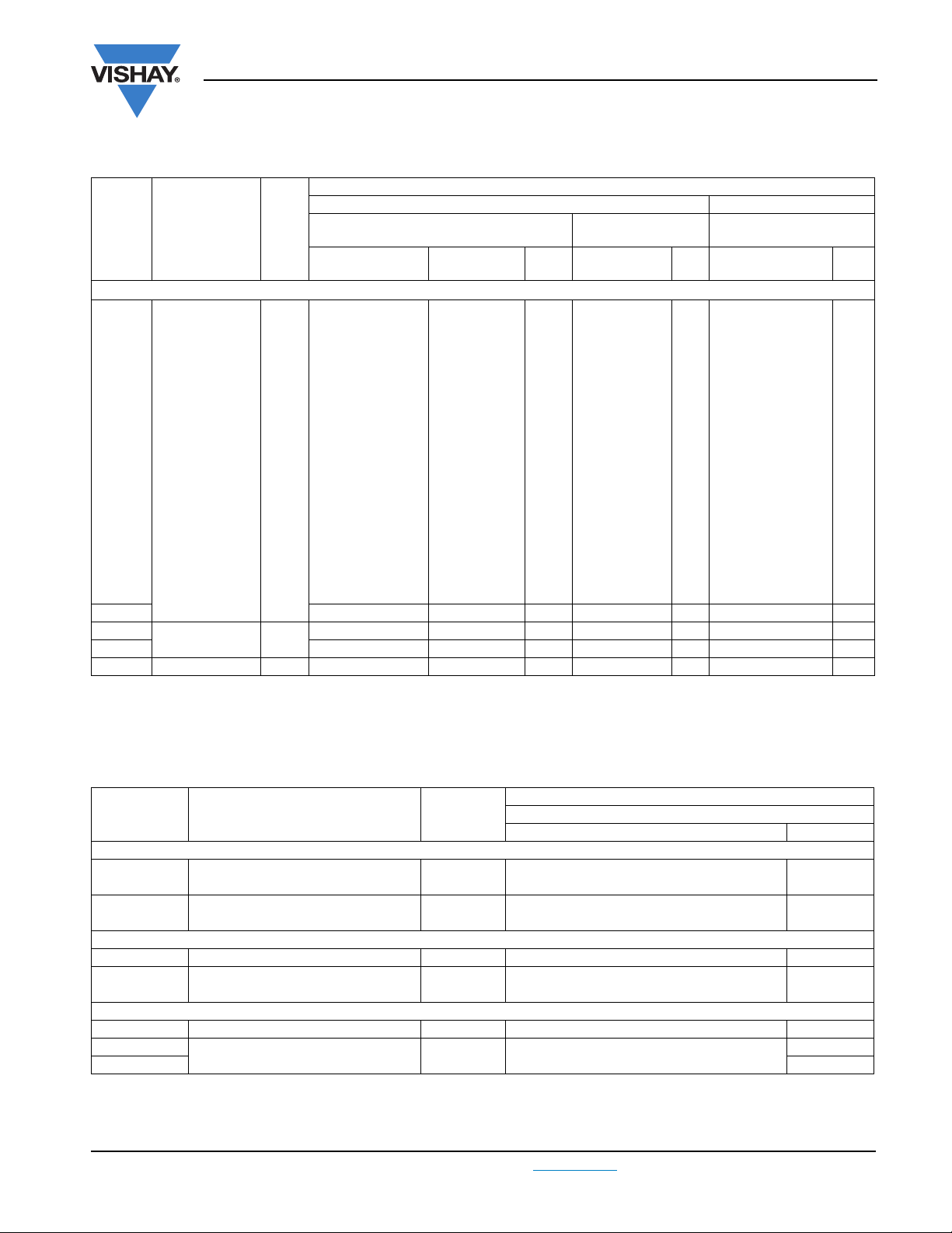
Pitch: 27.5 mm; C-tol. = ± 20 %
CATALOG NUMBER BFC2 338 ..... AND PACKAGING
C
(µF)
Pitch = 27.5 mm ± 0.4 mm; d
0.39
0.47 21474 23474 25474
0.56 21564 23564 25564
0.68 21684 23684 25684
0.82 21824 23824 25824
1.0
1.2 20125 22125 24125
1.5
1.8 20185 22185 24185
2.2 15.0 x 25.0 x 31.5 12.3 20225 22225 24225
2.7
3.3 20335 22335 24335
Note
(1)
Weight for short lead product only
DIMENSIONS
w xh xl
(mm)
= 0.80 mm ± 0.08 mm
t
9.0 x 19.0 x 31.5 5.5
11.0 x 21.0 x 31.0 7.4
13.0 x 23.0 x 31.0 9.2
18.0 x 28.0 x 31.5 16.1
MASS
(g)
(1)
l
= 3.5 mm
t
± 0.5 mm
21394 23394
21105 23105 25105
20155 22155 24155
20275 22275
Short leads Long leads
31.0 mm Pitch: 27.5 mm C-tol. = ± 10 %
CATALOG NUMBER BFC2 338 ..... AND PACKAGING
C
(µF)
Pitch = 27.5 mm ± 0.4 mm; d
1.0
1.5 13.0 x 23.0 x 31.0 9.2 28143 28343 28543
1.8
2.2 28145 28345
2.7 18.0 x 28.0 x 31.5 16.1 28146 28346 28546
Note
(1)
Weight for short lead product only
DIMENSIONS
w xh xl
(mm)
= 0.80 mm ± 0.08 mm
t
11.0 x 21.0 x 31.0 7.4
15.0 x 25.0 x 31.5 12.3
MASS
(g)
(1)
lt = 3.5 mm
± 0.5 mm
28141 28341
28144 28344 28544 100
Short leads Long leads
(2)
Pitch: 27.5 mm; C-tol. = ± 5 %
CATALOG NUMBER BFC2 338 ..... AND PACKAGING
C
(µF)
Pitch = 27.5 ± 0.4 mm; d
1 11.0 x 21.0 x 31.0 7.4 28241 28441 100 28641 125
1.2
1.5 28243 28443 28643
1.8 15.0 x 25.0 x 31.5 12.3 28244 28444 100 28644 100
2.2
2.7 28246 28446 28646
Note
(1)
Weight for short lead product only
www.vishay.com For technical questions, contact: rfi@vishay.com
155 Revision: 16-Jul-09
DIMENSIONS
w xh xl
(mm)
= 0.80 ± 0.08 mm
t
13.0 x 23.0 x 31.0 9.2
18.0 x 28.0 x 31.5 16.1
MASS
(g)
(1)
l
=
t
3.5 ± 0.5 mm
28242 28442
28245 28445
Short leads Long leads
LOOSE IN BOX
lt= 5.0 mm
± 1.0 mm
LOOSE IN BOX
lt = 5.0 mm
± 1.0 mm
LOOSE IN BOX
lt=
5.0 ± 1.0 mm
SPQ
100
50
SPQ
100
50
SPQ
100
50
lt= 25.0 mm
± 2.0 mm
25394
24275
lt = 25.0 mm
± 2.0 mm
28541
28545
lt=
25.0 ± 2.0 mm
28642
28645
Document Number: 28119
SPQ
150
125
100
75
SPQ
1251.2 28142 28342 28542
75
SPQ
125
75
Page 12

MKP 338 2 X2
Interference Suppression Film Capacitors
Vishay BCcomponents
MKP Radial Potted Type
SAFETY APPROVALS X2 VOLTAGE VALUE FILE NUMBERS
EN 60384-14 (ENEC)
(= IEC 60384-14 ed 3)
UL1414; CSA-C22.2 No.1 250 Vac 1 nF to 1 µF E112471
UL 1283 305 Vac 1 nF to 3.3 µF E109565
CSA-E384-14 310 Vac 1 nF to 3.3 µF 2123580
CQC 310 Vac 1 nF to 3.3 µF
CB-test certificate 310 Vac 1 nF to 3.3 µF FI 5123
The ENEC-Approval together with the CB-certificate replace all national marks of the following countries (they have already signed the
ENEC-Agreement): Austria; Belgium; Czech. Republic; Denmark; Finland; France; Germany; Greece; Hungary; Ireland; Italy; Luxembourg;
Netherlands; Norway; Portugal; Slovenian; Spain; Sweden; Switzerland; and United Kingdom.
MOUNTING
Normal use
The capacitors are designed for mounting on printed -circuit boards.The capacitors packed in bandoliers are designed for
mounting in pinted-circuit boards by means of automatic insertion machines. For detailed tape specifications refer to “Packaging
Information”. www.vishay.com/doc?28139
310 Vac 1 nF to 3.3 µF FI 2008038
CQC07001018685 (F)
CQC07001021279 (L)
CQC03001003071 (S)
16
C
®
US
CQC
Specific method of mounting to withstand vibration and shock
In order to withstand vibration and shock tests, it must be insured that the stand-off pips are in good contact with the printed-circuit
board:
• For pitches ≤ 15 mm capacitors shall be mechanically fixed by the leads
• For larger pitches the capacitors shall be mounted in the same way and the body clamped
Space requirements on printed circuit board
The maximum length and width of film capacitors is shown in the drawing:
• Eccentricity as in drawing. The maximum eccentricity is smaller than or equal to lead diameter of the product concerned
• Product heigth with seating plane as given by “IEC 60717”
as reference: h
Storage temperature
• Storage temperature: T
Ratings and characteristics reference conditions
≤ h + 0.3 mm or h
max.
= - 25 °C to + 40 °C with RH maximum 80 % without condesation
stg
≤ h’ + 0.3 mm.
max.
Eccentricity
= I + 0.3 mm
I
max.
b
= b + 0.3 mm
max.
Unless otherwise specified, all elctrical values apply to an ambient temperature of 23 °C ± 1 °C, an atmospheric pressure of
86 kPa to 106 kPa and a relative humidity of 50 °C ± 2 %.
For reference testing, a conditioning period shall be applied over 96 h ± 4 h by heating the products in a circulating air oven at
the rated temperature and a relative humidity not exceeding 20 %.
Document Number: 28119 For technical questions, contact: rfi@vishay.com
Revision: 16-Jul-09 156
www.vishay.com
Page 13

MKP 338 2 X2
Vishay BCcomponents
Interference Suppression Film Capacitors
MKP Radial Potted Type
CHARACTERISTICS
Capacitance as a function of ambient temperature (typical curve)
4
C/C
(%)
Δ
2
typical
0
max.
- 2
- 4
- 6
- 50
0 50 100T
Tangent of loss angle as a function of frequency (typical curve)
3
10
)
-4
amb
min.
(°C)
Impedance as a function of frequency (typical curve)
Resonant frequency as a function of capacitance (typical curve)
Dissipation
factor (x 10
2
10
1
10
0
10
1
10
3
10
AC voltage
(V)
2
10
220 nF < C ≤ 1 µF
47 nF < C ≤ 220 nF
< C ≤ 47 nF
10 nF
2
10
3
10
4
10
Max. RMS voltage as a function of frequency
(typical curve)
C > 1 µF
≤ 10 nF
C
f (Hz)
5
10
Max. RMS current as a function of frequency
(typical curve)
T
≤ 110 °C
amb
1
10
1
10
2
10
3
10
4
f (Hz)
10
5
10
www.vishay.com For technical questions, contact: rfi@vishay.com
Document Number: 28119
157 Revision: 16-Jul-09
Page 14

MKP 338 2 X2
Interference Suppression Film Capacitors
Vishay BCcomponents
MKP Radial Potted Type
Insulation resistance
6
10
RC (s)
5
10
4
10
0
20 40 60
APPLICATION NOTES
• For X2 electromagnetic interference suppression in standard across the line applications (50 Hz/60 Hz) with a maximum
mains voltage of 310 Vac
• For series impedance applications we refer to the application note www.vishay.com/doc?28153
• These capacitors are not intended for continuous pulse applications. For these situations, capacitors of the AC and pulse
programs must be used.
• The maximum ambient temperature must not exceed 110 °C (125 °C for less than 1000 h) for C ≤ 470 nF and 110 °C for
C > 470 nF
• Rated voltage pulse slope:
If the pulse voltage is lower than the rated voltage, the values of the specific reference data can be multiplied by 435 Vdc and
divided by the applied voltage.
80
T
100
amb
(°C)
INSPECTION REQUIREMENTS
GENERAL NOTES
1. Sub-clause numbers of tests and performance requirements refer to the “Sectional Specification, IEC Publication
IEC 60384-14 ed-3 and “Specific Reference Data”
Group C inspection requirements
SUB-CLAUSE NUMBER AND
TEST
SUB-GROUP C1A PART OF
SAMPLE OF SUB-GROUP C1
4.1 Dimensions (detail) As specified in chapters “General Data” of this
Initial measurements Capacitance
4.3 Robustness of
terminations
Document Number: 28119 For technical questions, contact: rfi@vishay.com
Revision: 16-Jul-09 158
CONDITIONS PERFORMANCE REQUIREMENTS
specification
Tangent of loss angle:
For C ≤ 1 µF at 10 kHz
For C > 1 µF at 1 kHz
Tensile: load 10 N; 10 s
Bending: load 5 N; 4 x 90°
No visible damage
www.vishay.com
Page 15

MKP 338 2 X2
Vishay BCcomponents
Interference Suppression Film Capacitors
MKP Radial Potted Type
SUB-CLAUSE NUMBER AND
TEST
4.4 Resistance to
soldering heat
4.19 Component solvent
resistance
4.4.2 Final measurements Visual examination
SUB-GROUP C1B PART OF
SAMPLE OF SUB-GROUP C1
Initial measurements Capacitance
4.20 Solvent resistance
of the marking
4.6 Rapid change of
temperature
4.6.1 Inspection Visual examination No visible damage
4.7 Vibration (see note 3.1) Mounting: see Section “Mounting” of this
4.7.2 Final inspection Visual examination No visible damage
4.9 Shock (see note 3) Mounting: see Section “Mounting” for more
CONDITIONS PERFORMANCE REQUIREMENTS
No pre-drying
Method: 1A
Solder bath: 280 °C ± 5 °C
Duration: 10 s
Isopropylalcohol at room temperature
Method: 2
Immersion time: 5 min ± 0.5 min
Recovery time:
Min 1 h, max 2 h
No visible damage
Legible marking
Capacitance
Tangent of loss angle
Insulation resistance
Tangent of loss angle:
For C ≤ 1 µF at 10 kHz
For C > 1 µF at 1 kHz
Isopropylalcohol at room temperature
Method: 1
Rubbing material: cotton wool
Immersion time: 5 min ± 0.5 min
θA = - 55 °C
θB = + 110 °C
5 cycles
Duration t = 30 min
specification
Procedure B4
Frequency range: 10 Hz to 55 Hz.
Amplitude: 0.75 mm or
Acceleration 98 m/s²
(whichever is less severe)
Total duration 6 h
information
Pulse shape: half sine
Acceleration: 490 m/s²
Duration of pulse: 11 ms
¦ΔC/C¦ ≤ 5 % of the value measured initially.
Increase of tan δ:
≤ 0.008 for: C ≤ 1 µF or
≤ 0.005 for: C > 1 µF
Compared to values measured initially
As specified in section “Insulation Resistance”
this specification
No visible damage
Legible marking
of
www.vishay.com For technical questions, contact: rfi@vishay.com
159 Revision: 16-Jul-09
Document Number: 28119
Page 16

MKP 338 2 X2
Interference Suppression Film Capacitors
MKP Radial Potted Type
SUB-CLAUSE NUMBER AND
TEST
4.9.2 Final measurements Visual examination
SUB-GROUP C1
COMBINED SAMPLE OF
SPECIMENS OF SUB-GROUPS
C1A AND C1B
4.11 Climatic sequence
4.11.1 Initial measurements Capacitance
CONDITIONS PERFORMANCE REQUIREMENTS
Capacitance
Tangent of loss angle
Insulation resistance
Measured in 4.4.2 and 4.9.2
Tangent of loss angle:
Measured initially in C1A and C1B
Vishay BCcomponents
No visible damage
¦ΔC/C¦ ≤ 5 % of the value measured initially.
Increase of tan δ:
≤ 0.008 for: C ≤ 1 µF or
≤ 0.005 for: C > 1 µF
Compared to values measured initially
As specified in section “Insulation Resistance” of
this specification
4.11.2 Dry heat Temperature: 110 °C
4.11.3 Damp heat cyclic
Test Db
First cycle
4.11.4 Cold Temperature: - 55 °C
4.11.5 Damp heat cyclic
Test Db
Remaining cycles
4.11.6 Final measurements Visual examination
SUB GROUP C2
Duration: 16 h
Duration: 2 h
Capacitance
Tangent of loss angle
Voltage proof
1350 Vdc; 1 min between terminations
Insulation resistance
No visible damage
Legible marking
¦ΔC/C¦ ≤ 5 % of the value measured in 4.11.1.
Increase of tan δ:
≤ 0.008 for: C ≤ 1 µF or
≤ 0.005 for: C > 1 µF
Compared to values measured in 4.11.1.
No permanent breakdown or flash-over
≥ 50 % of values specified in section “Insulation
Resistance” of this specification
4.12 Damp heat steady state 56 days; 40 °C; 90 % to 95 % RH
no load
4.12.1 Initial measurements Capacitance
Tangent of loss angle: at 1 kHz
Document Number: 28119 For technical questions, contact: rfi@vishay.com
Revision: 16-Jul-09 160
www.vishay.com
Page 17

MKP 338 2 X2
Vishay BCcomponents
SUB-CLAUSE NUMBER AND
TEST
4.12.3 Final measurements Visual examination
SUB-GROUP C3
4.13.1 Initial measurements Capacitance
Interference Suppression Film Capacitors
CONDITIONS PERFORMANCE REQUIREMENTS
Capacitance
Tangent of loss angle
Voltage proof
1350 Vdc; 1 min between term.
Insulation resistance
Tangent of loss angle:
For C ≤ 1 µF at 10 kHz
For C > 1 µF at 1 kHz
MKP Radial Potted Type
No visible damage
Legible marking
¦ΔC/C¦ ≤ 5 % of the value measured in 4.12.1.
Increase of tan δ:
≤ 0. 008 for: C ≤ 1 µF or
≤ 0. 005 for: C > 1 µF
Compared to values measured in 4.12.1.
No permanent breakdown or flash-over
≥ 50 % of values specified in section “Insulation
Resistance” of this specification
4.13 Impulse voltage 3 successive impulses, full wave, peak voltage:
X2: 2.5 kV for C ≤ 1 µF
X2: 2.5 kV/√C for C > 1 µF
Max.24 pulses
4.14 Endurance Duration: 1000 h
1.25 x U
Once in every hour the voltage is increased to
1000 V (RMS) for 0.1 s via resistor of 47 Ω ± 5 %
4.14.7 Final measurements Visual examination
Capacitance
Tangent of loss angle
Voltage proof
1350 Vdc; 1 min between
terminations.
2120 Vac; 1 min between
terminations and case.
Insulation resistance
at 110 °C
Rac
No selfhealing breakdowns or flashover
No visible damage
Legible marking
¦ΔC/C¦ ≤ 10 % compared to values measured in
4.13.1.
Increase of tan δ:
≤ 0.008 for: C ≤ 1 µF or
≤ 0.005 for: C > 1 µF
Compared to values measured in 4.13.1.
No permanent breakdown or flash-over
≥ 50 % of values specified in section “Insulation
Resistance” of this specification
www.vishay.com For technical questions, contact: rfi@vishay.com
161 Revision: 16-Jul-09
Document Number: 28119
Page 18

MKP 338 2 X2
Interference Suppression Film Capacitors
SUB-CLAUSE NUMBER AND
TEST
SUB-GROUP C4
4.15 Charge and discharge
4.15.1 Initial measurements Capacitance
4.15.3 Final measurements Capacitance
CONDITIONS PERFORMANCE REQUIREMENTS
10 000 cycles
Charge to 435 Vdc
Discharge resistance:
---------------------------------------------------
R
=
1.25 x C dU dt⁄()
Tangent of loss angle:
For C ≤ 1 µF at 10 kHz
For C > 1 µF at 1 kHz
Tangent of loss angle
Vishay BCcomponents
MKP Radial Potted Type
435 Vdc
¦ΔC/C¦ ≤ 10 % compared to values measured in
4.15.1.
Increase of tan δ:
≤ 0.008 for: C ≤ 1 µF or
≤ 0.005 for: C > 1 µF
Compared to values measured in 4.15.1.
Insulation resistance
SUB-GROUP C5
4.16 Radio frequency
characteristic
SUB-GROUP C6
4.17 Passive flammability
Class B
SUB-GROUP C7
4.18 Active flammability 20 cycles of 2.5 kV discharges on the test
Resonance frequency ≥ 0.9 times the value as specified in section
Bore of gas jet: Ø 0.5 mm
Fuel: butane
Test duration for actual volume V in mm³:
V ≤ 250: 10 s
250 < V ≤ 500: 20 s
500 < V ≤ 1750: 30 s
V > 1750: 60 s
One flame application
capacitor connected to U
Rac
≥ 50 % of values specified in section “Insulation
Resistance” of this specification
“Resonant Frequency” of this specification
After removing test flame from capacitor, the
capacitor must not continue to burn for more than
10 s. No burning particle must drop from the
sample.
The cheese cloth around the capacitors shall not
burn with a flame.
No electrical measurements are required.
Document Number: 28119 For technical questions, contact: rfi@vishay.com
Revision: 16-Jul-09 162
www.vishay.com
Page 19

Legal Disclaimer Notice
Vishay
Disclaimer
All product specifications and data are subject to change without notice.
Vishay Intertechnology, Inc., its affiliates, agents, and employees, and all persons acting on its or their behalf
(collectively, “Vishay”), disclaim any and all liability for any errors, inaccuracies or incompleteness contained herein
or in any other disclosure relating to any product.
Vishay disclaims any and all liability arising out of the use or application of any product described herein or of any
information provided herein to the maximum extent permitted by law. The product specifications do not expand or
otherwise modify Vishay’s terms and conditions of purchase, including but not limited to the warranty expressed
therein, which apply to these products.
No license, express or implied, by estoppel or otherwise, to any intellectual property rights is granted by this
document or by any conduct of Vishay.
The products shown herein are not designed for use in medical, life-saving, or life-sustaining applications unless
otherwise expressly indicated. Customers using or selling Vishay products not expressly indicated for use in such
applications do so entirely at their own risk and agree to fully indemnify Vishay for any damages arising or resulting
from such use or sale. Please contact authorized Vishay personnel to obtain written terms and conditions regarding
products designed for such applications.
Product names and markings noted herein may be trademarks of their respective owners.
Document Number: 91000 www.vishay.com
Revision: 18-Jul-08 1
 Loading...