

Page 1
MK3235
ICRO
C
LOCK
Description
The MK3235 is the smallest size, lowest power system
clock synthesizer available. It is the ideal way to
generate clocks for handheld computers, such as PDAs,
PICs, and other devices where low power is required.
Using analog Phase-Locked Loop (PLL) techniques,
the device operates from a single 32.768 kHz crystal to
produce the 32.768kHz, 14.318MHz, and serial
communications output clocks.
The device has three power down modes for the
14.3MHz, communications, and 32.768kHz clocks.
The MK3235 can save board space and cost even if it
only replaces the 32kHz oscillator circuitry and one
additional surface mount crystal or oscillator. The
extremely low IDD, the ease of surface mounting, and
the power down capability are added benefits in using
the part.
Handheld System Clock Synthesizer
Features
• Input crystal frequency of 32.768 kHz
• Lowest power solution available
• Lowest profile clock solution where height is critical
• Three output clocks
• 3.3V or 5.0V operation
• Duty cycle of 45/55
• 14.3MHz or 14.3MHz+Comm clock power downs
• Separate battery supply pin for 32 kHz runs to 2V
• IDD less than 4µA when 32 kHz running
• Packaged in 16 pin narrow SOIC
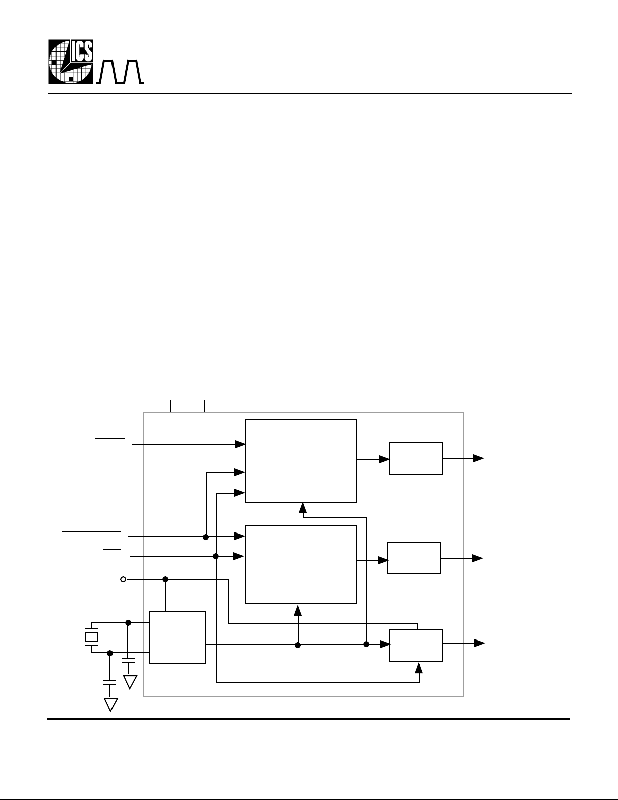
Block Diagram
PD14
PDCOMM
PD
VDD32
32.768 kHz
crystal
X1
X2
VDD GND
Crystal
Oscillator
14.318MHz
Clock Synthesis
and Control
Circuitry
Communications
Clock Synthesis
and Control
Circuitry
Output
Buffer
Output
Buffer
Output
Buffer
14.3 MHz
1.843 or
3.686 MHz
32.768 kHz
MDS 3235 D 1 Revision 092397 Printed 11/16/00
Integrated Circuit Systems, Inc.•525 Race Street•San Jose•CA•95126•(408)295-9800tel•www.icst.com
Page 2
MK3235
ICRO
C
LOCK
Handheld System Clock Synthesizer
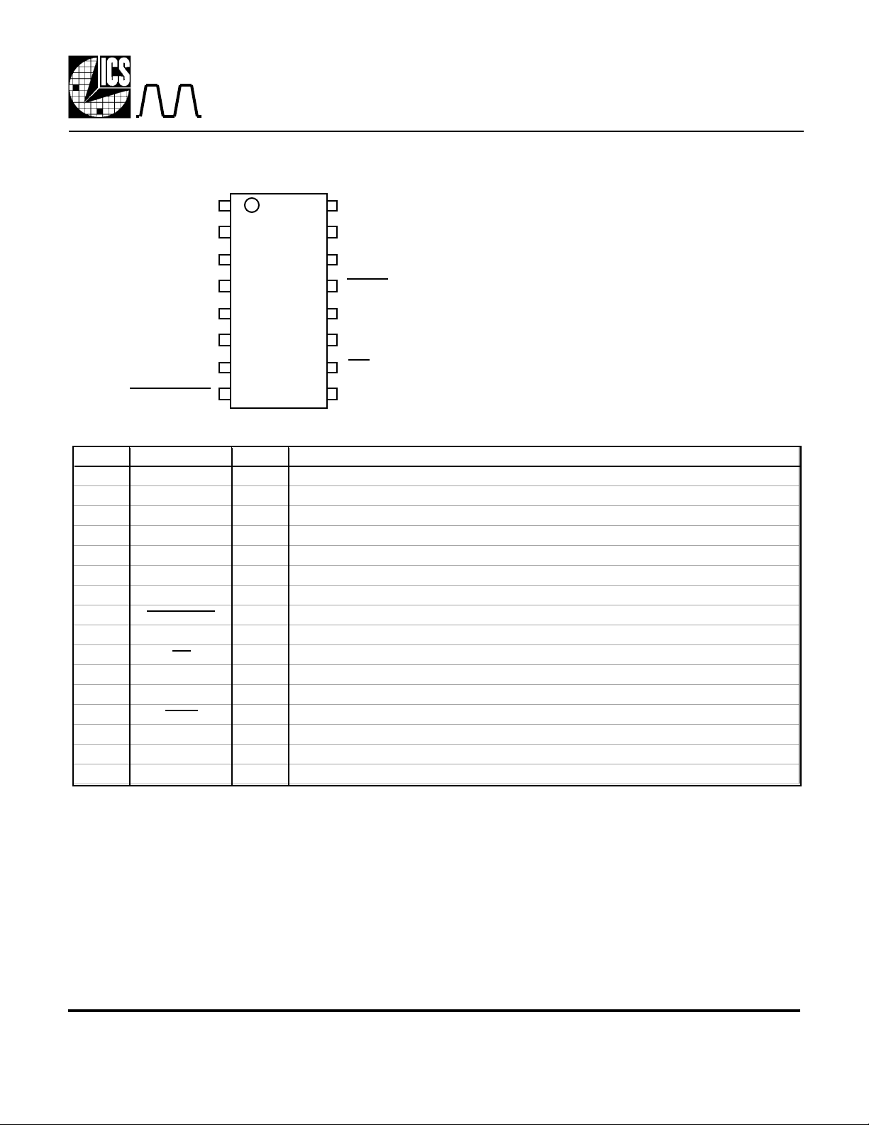
Pin Assignment
X2
X1
VDD32
VDD
GND
COMMCLK
32K
PDCOMM
1
2
3
4
5
6
7 10
8 9
16
15
14
13
12
11
GND
GND
VDD
PD14
GND
14.3M
PD
GND
Pin Descriptions
Number Name Type Description
1 X2 O Crystal connection. Connect to 32.768 kHz crystal.
2 X1 I Crystal connection. Connect to 32.768 kHz crystal.
3 VDD32 P Separate power supply connection for 32.768kHz clock. Will operate to 2.0V.
4 VDD P Connect to +3.3V or +5V. Must be the same voltage as pin 14.
5 GND P Connect to ground.
6 COMMCLK O Serial communications (1.84 on -01 version, or 3.68MHz on -02 version) clock output.
7 32K O 32.768 kHz square wave clock output.
8 PDCOMM I Power Down serial Communications and 14.3M clock outputs (stop low) when low.
9 GND P Connect to ground.
10 PD I Powers Down everything but 32kHz oscillator internally. 32kHz output buffer is off.
11 14.3M O 14.318 MHz output clock.
12 GND P Connect to ground.
13 PD14 I Power Down 14.318MHz clock output (stops low) when low.
14 VDD P Connect to +3.3V or +5V. Must be the same voltage as pin 4.
15 GND P Connect to ground.
16 GND P Connect to ground.
Type: I = Input, O = output, P = power supply connection
Power Down status: Output clocks will stop in a low state when powered down
External Components
The MK3235 requires a minimum number of external components for proper operation. Decoupling
capacitors of 0.1µF should be connected between VDD and GND, and VDD32 and GND, as close to the
MK3235 as possible. A series resistor should be used on the VDD32 supply. A series termination resistor of
33Ω may be used for each clock output, except the 32.768 kHz. For tuning the real time clock output, use
a 32.768 kHz crystal with a load capacitance of 12.5pF, and connect a 20pF±5% (NPO dielectric)
capacitor between each crystal pin and ground. The 32.768 kHz crystal must be connected as close to the
chip as possible. Consult MicroClock for a recommended external circuit schematic.
MDS 3235 D 2 Revision 092397 Printed 11/16/00
Integrated Circuit Systems, Inc.•525 Race Street•San Jose•CA•95126•(408)295-9800tel•www.icst.com
Page 3
MK3235
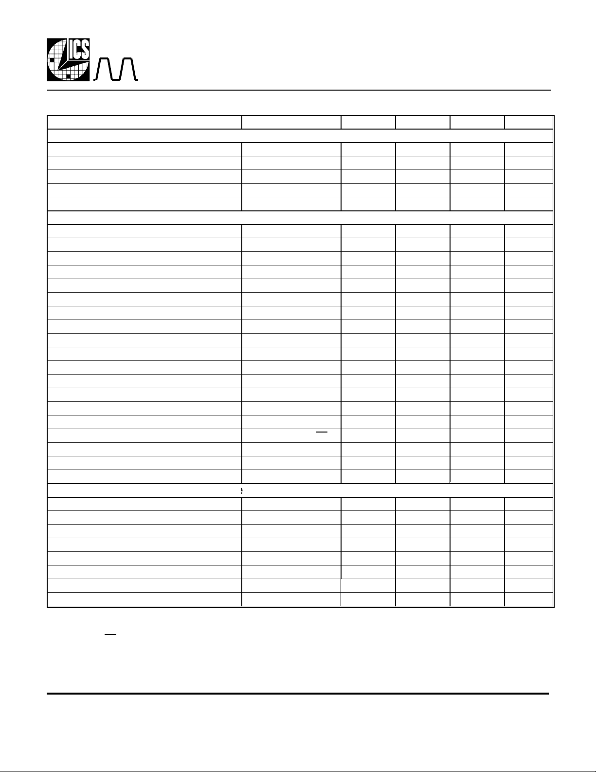
ABSOLUTE MAXIMUM RATINGS (note 1)
DC CHARACTERISTICS (at 5.0V unless otherwise noted)
AC CHARACTERISTICS (at 5.0V unless otherwise noted)
32.768kHz crystal with ESR ≤25kΩ
32.768kHz oscillator running
ICRO
C
LOCK
Handheld System Clock Synthesizer
Electrical Specifications
Parameter Conditions Minimum Typical Maximum Units
Supply Voltage, VDD Referenced to GND 7 V
Inputs and Clock Outputs Referenced to GND -0.5 VDD+0.5 V
Ambient Operating Temperature 0 70 °C
Soldering Temperature Max of 30 seconds 260 °C
Storage Temperature -65 150 °C
Operating Voltage, VDD 3.0 5.5 V
Operating Voltage,VDD32 2.0 5.5 V
Input High Voltage, VIH VDD=5V 2.0 V
Input Low Voltage, VIL VDD=5V 0.8 V
Output High Voltage, VOH, 3.3V or 5V IOH=-4mA VDD-0.4 V
Output High Voltage, VOH VDD=5V, IOH=-25mA 2.4 V
Output Low Voltage, VOL VDD=5V, IOL=25mA 0.4 V
Input High Voltage, VIH VDD=3.3V 1.9 V
Input Low Voltage, VIL VDD=3.3V 0.4 V
Output High Voltage, VOH VDD=3.3V, IOH=-8mA 2.4 V
Output Low Voltage, VOL VDD=3.3V, IOL=8mA 0.4 V
IDD Operating Supply Current, 5V No Load 9 mA
IDD32 with only 32 kHz running, 5V No Load 3.5 µA
IDD Operating Supply Current, 3.3V No Load 6 mA
IDD32 with only 32 kHz output running, 3.3V No Load 2.5 µA
IDD32, only 32 kHz osc. running, 3.3V, note 2 32kHz output off. PD=0 1 µA
Short Circuit Current, 5V 32kHz output ±30 mA
Short Circuit Current, 5V 14, 1.8MHz outputs ±80 mA
Input Capacitance 7 pF
Input Frequency 32.768 kHz
Output Clock Rise and Fall Time, 0.2 to 0.8VDD 2 ns
Output Clock Duty Cycle, all MHz clocks At VDD/2 45 49 to 51 55 %
32.768 kHz Clock Duty Cycle At VDD32/2 57 %
Absolute Clock Period Jitter 14.318 MHz -500 500 ps
Power up time, to all clocks stable, 32k running VDD=3.3 or 5V 9 ms
Power on time,VDD32=0V to all clocks stable
Power on time, all power down pins taken high
Note 1: Stresses beyond those listed under Absolute Maximum Ratings could cause permanent damage to the device. Prolonged
exposure to levels above the operating limits but below the Absolute Maximums may affect device reliability.
Note 2: When PD=0 (low) and VDD32 is greater than 2.0V, then the 32kHz oscillator will continue to run on the chip, but the
output is turned off. This allows for a quick power-up (<20ms), while the chip is only consuming approximately 1µA.
MDS 3235 D 3 Revision 092397 Printed 11/16/00
Integrated Circuit Systems, Inc.•525 Race Street•San Jose•CA•95126•(408)295-9800tel•www.icst.com
500 1000 ms
15 ms
Page 4
MK3235
Inches
Millimeters
ICRO
C
LOCK
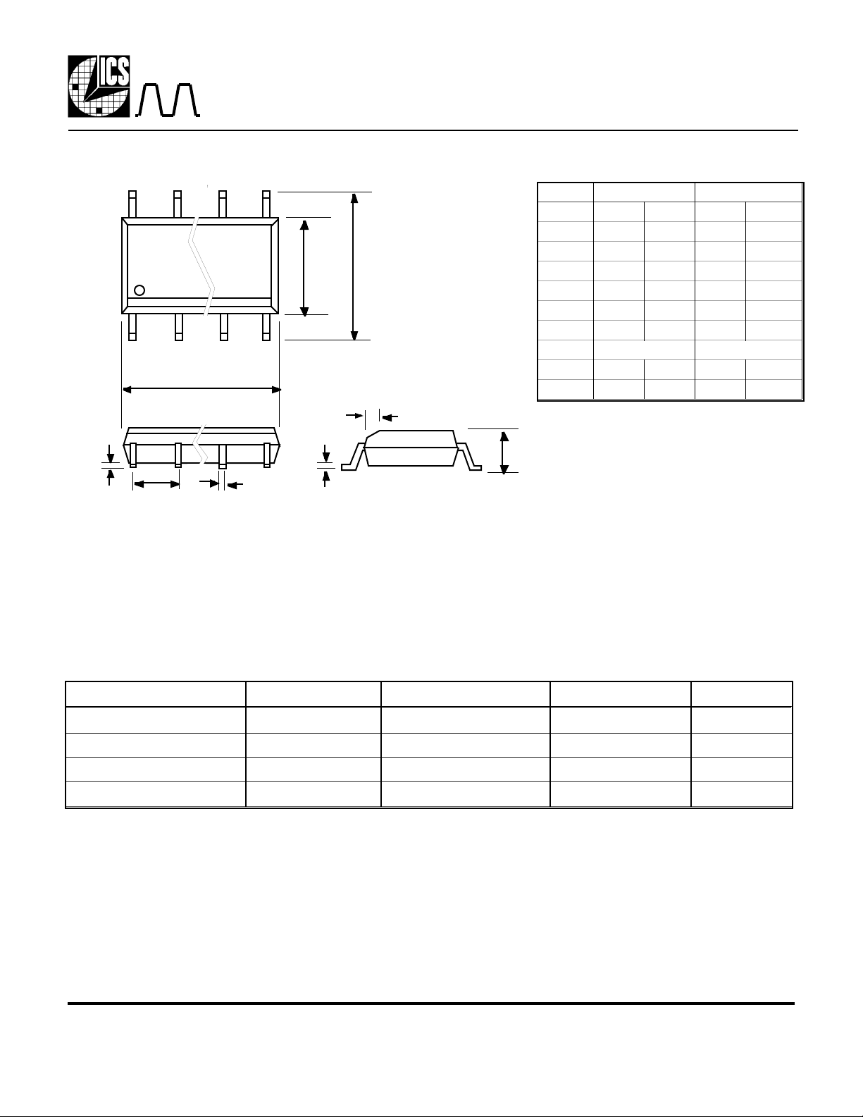
Package Outline and Package Dimensions
E H
h x 45°
D
Q
e
b
c
Handheld System Clock Synthesizer
16 pin SOIC narrow
Symbol Min Max Min Max
A 0.055 0.068 1.397 1.7272
b 0.013 0.019 0.330 0.483
c 0.007 0.010 0.191 0.254
D 0.385 0.400 9.779 10.160
E 0.150 0.160 3.810 4.064
H 0.225 0.245 5.715 6.223
e
h 0.016 0.406
Q 0.004 0.01 0.102 0.254
A
Ordering Information
Part/Order Number Marking Communications Clock Package Temperature
MK3235-01S MK3235-01S 1.843 MHz 16 pin SOIC 0-70°C
MK3235-02S MK3235-02S 3.686 MHz 16 pin SOIC 0-70°C
MK3235-01STR MK3235-01S 1.843 MHz Add Tape & Reel 0-70°C
MK3235-02STR MK3235-02S 3.686 MHz Add Tape & Reel 0-70°C
While the information presented herein has been checked for both accuracy and reliability, MicroClock Incorporated assumes no responsibility for either its use or for the
infringement of any patents or other rights of third parties, which would result from its use. No other circuits, patents, or licenses are implied. This product is intended for use in
normal commercial applications. Any other applications such as those requiring extended temperature range, high reliability, or other extraordinary environmental requirements
are not recommended without additional processing by MicroClock. MicroClock reserves the right to change any circuitry or specifications without notice. MicroClock does not
authorize or warrant any MicroClock product for use in life support devices or critical medical instruments.
MDS 3235 D 4 Revision 092397 Printed 11/16/00
Integrated Circuit Systems, Inc.•525 Race Street•San Jose•CA•95126•(408)295-9800tel•www.icst.com
 Loading...