

Page 1
MK2712
NTSC/PAL Clock Source
Description
The MK2712 is the ideal way to generate clocks for
NTSC/PAL video encoders and decoders. Stored in
the device are two sets of popular frequencies for
NTSC and PAL. In an 8 pin SOIC, the chip can save
component count, board space, and cost over surface
mount crystals and oscillators, and increase reliability
by eliminating one or two mechanical devices from the
board. The power down pin turns off the device,
drawing less than 20µA.
ICS/MicroClock offers many other clocks for computers
and computer peripherals. Consult us when you need
to remove crystals and oscillators from your board.
Features
• Packaged in 8 pin SOIC
• Ideal for chips such as Analog Devices AD722
and Brooktree BT819
• Input clock frequency of 27.0000 MHz
• Power down turns off chip
• Output enable tri-states output for system testing
• Frequencies are within 1 ppm with accurate
input clock
• Low jitter
• Output clock frequencies of 14.31818MHz,
17.7345MHz, 28.6364MHz, or 35.46896MHz
• 25mA drive capability at TTL levels
• 3.3V or 5V supply voltage
• Advanced, low power CMOS process
• Insensitive to input clock duty cycle
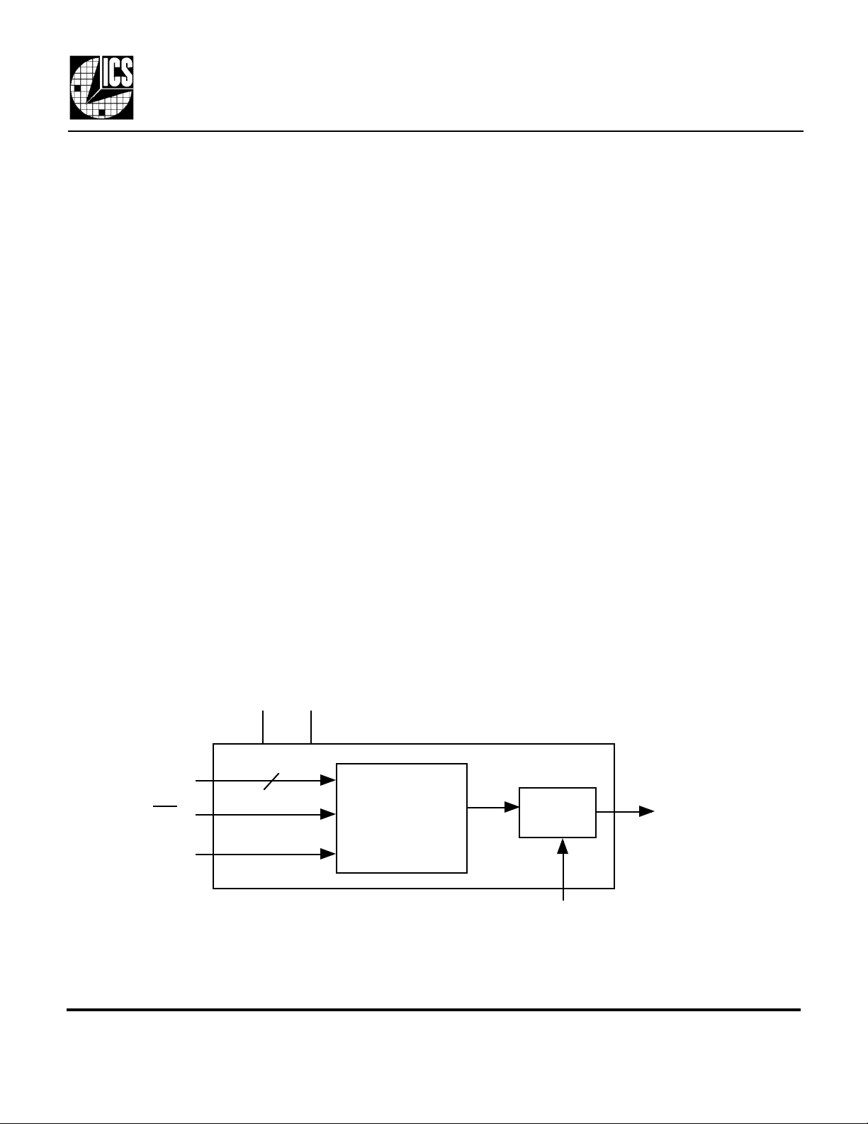
Block Diagram
VDD GND
FS0, 1
PD
27.00 MHz
clock input
MDS 2712 C 1 Revision 061401
Integrated Circuit Systems • 525 Race Street • San Jose • CA • 95126 • (408)295-9800tel • www.icst.com
2
PLL
Clock Synthesis
Circuitry
Output
Buffer
OE
NTSC/PALCL
OCK
Page 2
MK2712
Description
Input Clock. Connect to a 27.0000 MHz clock.
Connect to +3.3V or +5V.
Connect to ground.
NTSC or PAL output clock. Selected by FS1, FS0 per tables above.
Frequency Select pin #1. Selects NTSC or PAL frequency per table above.
Output Enable. Tri-states clock output when this input is low. Internal pull-up.
Power Down. Active low. Clocks stop low.
Frequency Select pin #0. Selects NTSC or PAL frequency per table above.
NTSC/PAL Clock Source
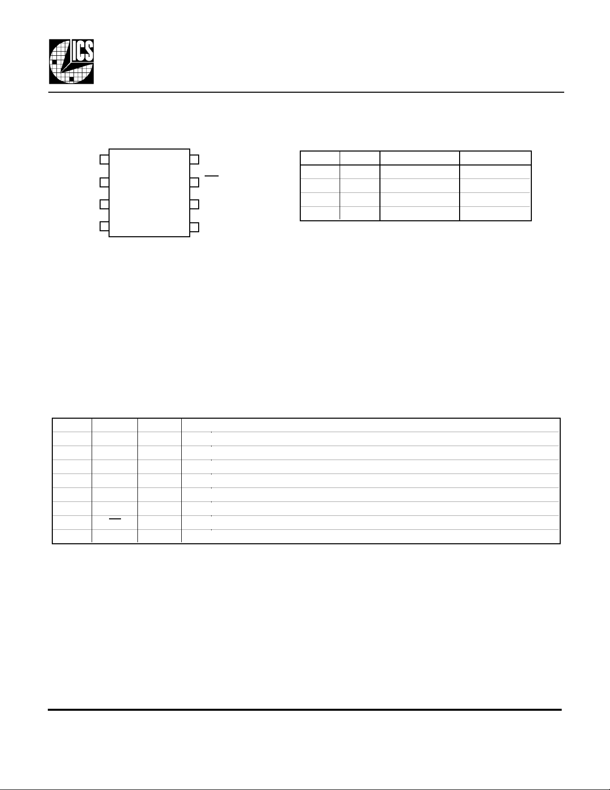
Pin Assignment
ICLK
GND
NPCLK
1 8
2
3
4
8 pin SOIC
Pin Descriptions
Decoding Table
FS0
7
PDVDD
6
OE
5
FS1
FS1 FS0 NPCLK (MHz) Error (ppm)
0 0 14.31818 0.3 ppm
0 1 17.73447 0.3 ppm
1 0 28.63636 0.3 ppm
1 1 35.46894 0.3 ppm
Number Name Type
1 ICLK I
2 VDD P
3 GND P
4 NPCLK O
5 FS1 I
6 OE I
7 PD I
8 FS0 I
Key: I = Input, O = output, P = power supply connection
External Components/Crystal Selection
A minimum number of external components are required for proper oscillation. Connect a 27.000 MHz clock to
ICLK. A decoupling capacitor of 0.1µF should be connected between VDD and GND on pins 2 and 3, and a 33Ω
terminating resistor should be used on the clock output if the trace is longer than 1 inch.
Description
Input Clock. Connect to a 27.0000 MHz clock.
Connect to +3.3V or +5V.
Connect to ground.
NTSC or PAL output clock. Selected by FS1, FS0 per tables above.
Frequency Select pin #1. Selects NTSC or PAL frequency per table above.
Output Enable. Tri-states clock output when this input is low. Internal pull-up.
Power Down. Active low. Clocks stop low.
Frequency Select pin #0. Selects NTSC or PAL frequency per table above.
MDS 2712 C 2 Revision 061401
Integrated Circuit Systems • 525 Race Street • San Jose • CA • 95126 • (408)295-9800tel • www.icst.com
Page 3
MK2712
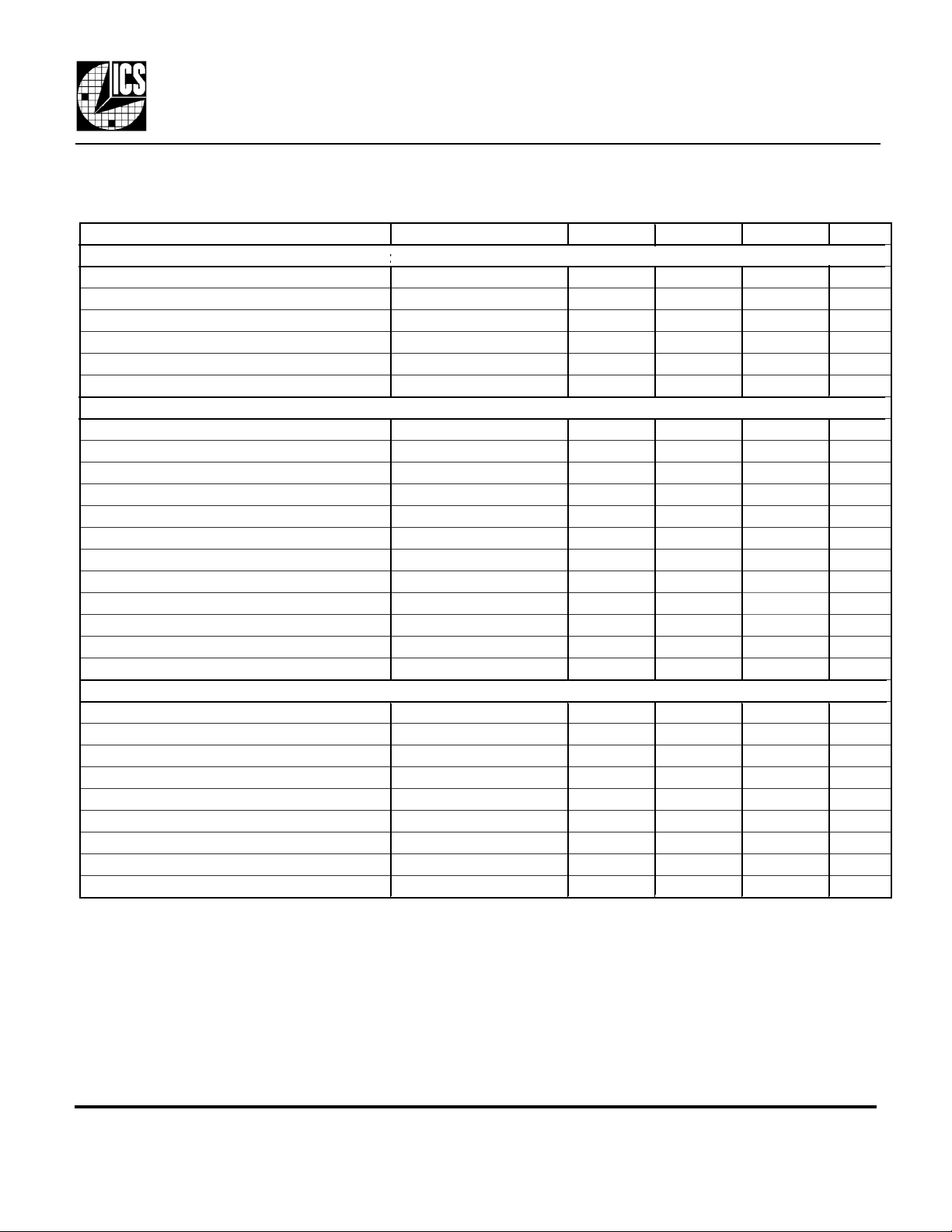
ABSOLUTE MAXIMUM RATINGS (note 1)
DC CHARACTERISTICS (at 5.0V unless otherwise noted)
AC CHARACTERISTICS (at 5.0V unless otherwise noted)
NTSC/PAL Clock Source
Electrical Specifications
Parameter Conditions Minimum Typical Maximum Units
Supply Voltage, VDD Referenced to GND 7 V
Inputs Referenced to GND -0.5 VDD+.5V V
Clock Outputs Referenced to GND -0.5 VDD+.5V V
Ambient Operating Temperature 0 70 °C
Soldering Temperature Max of 10 seconds 260 °C
Storage temperature -65 150 °C
Operating Voltage, VDD 4.5 5.5 V
Input High Voltage, VIH, input clock only ICLK pin 3.5 2.5 V
Input Low Voltage, VIL, input clock only ICLK pin 2.5 1.5 V
Input High Voltage, VIH 2 V
Input Low Voltage, VIL 0.8 V
Output High Voltage, VOH IOH=-4mA VDD-0.4 V
Output High Voltage, VOH IOH=-25mA 2.4 V
Output Low Voltage, VOL IOL=25mA 0.4 V
Operating Supply Current, IDD No Load, FS1=1. FS0=1 13 mA
Power Down Supply Current, IDDPD No Load 10 µA
Input Capacitance 5 pF
Actual Mean Frequency versus Target With exact ICLK 0.3 0.3 ppm
Input Clock Frequency 27 MHz
Input Clock Duty Cycle Time above 2.5V 20 80 %
Output Clock Rise Time 0.8 to 2.0V 1.5 ns
Output Clock Fall Time 2.0 to 0.8V 1.5 ns
Output Clock Duty Cycle Time above 1.5V 40 50 60 %
Absolute Maximum Clock Period Jitter, 15 pF Variation from mean ± 90 ps
One Sigma Clock Period Jitter, 15 pF load 30 ps
Absolute Maximum Clock Period Jitter, 15 pF VDD=3.3V ± 180 ps
One Sigma Clock Period Jitter, 15 pF load VDD=3.3V 50 ps
Notes:
1. Stresses beyond those listed under Absolute Maximum Ratings could cause permanent damage to the device.
Prolonged exposure to levels above the operating limits but below the Absolute Maximums may affect device
reliability.
2. Typical values are at 25°C.
MDS 2712 C 3 Revision 061401
Integrated Circuit Systems • 525 Race Street • San Jose • CA • 95126 • (408)295-9800tel • www.icst.com
Page 4
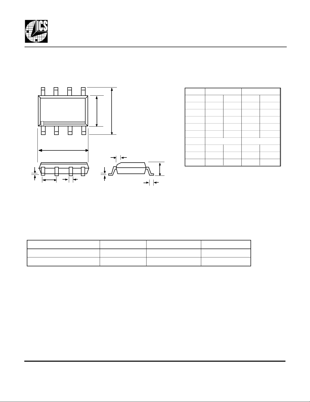
Package Outline and Package Dimensions
Inches
Millimeters
8 pin SOIC
E H
Pin 1
h x 45°
Q
e
b
c
D
L
MK2712
NTSC/PAL Clock Source
Symbol Min Max Min Max
A 0.055 0.061 1.397 1.5494
b 0.013 0.019 0.330 0.483
D 0.185 0.200 4.699 5.080
E 0.150 0.160 3.810 4.064
H 0.225 0.245 5.715 6.223
e
h 0.015 0.381
L 0.016 0.035 0.406 0.889
Q 0.004 0.01 0.102 0.254
A
Ordering Information
Part/Order Number Marking Package Temperature
MK2712S MK2712S 8 pin SOIC 0-70°C
MK2712STR MK2712S Add tape and reel 0-70°C
While the information presented herein has been checked for both accuracy and reliability, Integrated Circuit Systems, Inc (ICS) assumes no
responsibility for either its use or for the infringement of any patents or other rights of third parties, which would result from its use. No other circuits,
patents, or licenses are implied. This product is intended for use in normal commercial applications. Any other applications such as those requiring
extended temperature range, high reliability, or other extraordinary environmental requirements are not recommended without additional processing by
ICS. ICS reserves the right to change any circuitry or specifications without notice. ICS does not authorize or warrant any ICS product for use in life
support devices or critical medical instruments.
MDS 2712 C 4 Revision 061401
Integrated Circuit Systems • 525 Race Street • San Jose • CA • 95126 • (408)295-9800tel • www.icst.com
 Loading...