

Page 1
COMPLEMENTARY SILICON PNP TRANSISTORS
■ SGS-THOMSON PREFERRED SALESTYPES
■ LOW COLLECTOR-EMITTERSATURATION
VOLTAGE
■ FAST SWITCHING SPEED
APPLICATIONS
■ GENERALPURPOSESWITCHING
■ GENERALPURPOSEAMPLIFIER
MJD44H11
MJD45H11
3
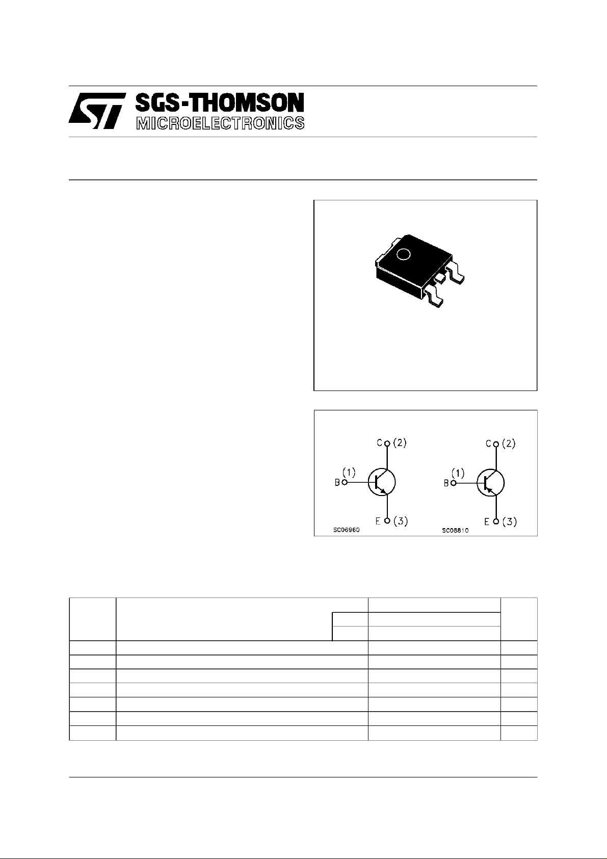
DESCRIPTION
1
The MJD44H11 is a silicon multiepitaxial planar
NPN transistors mounted in DPAK plastic
package.
It is inteded for various switching and general
DPAK
(TO-252)
purpose applications.
The complementaryPNPtype is MJD45H11.
INTERNAL SCHEMATIC DIAGRAM
ABSOLUTE MAXIMUM RATINGS
Symb o l Parameter Val u e Uni t
NPN MJD44 H11
PNP MJD45H11
V
V
I
P
T
For PNP types the values are intented negative.
Collector-Emitter Volta ge ( IB=0) 80 V
CEO
Emitter-Base Voltage ( IC=0) 5 V
EBO
Collect or Current 8 A
I
C
Collect or Peak Cur rent 16 A
CM
Tot al Di s sipation at Tc≤ 25oC20W
tot
Storage T emperature -55 t o 15 0
stg
Max. Operating Junction Temperature 150
T
j
o
C
o
C
July 1997
1/5
Page 2
MJD44H11 / MJD45H11
THERMAL DATA
R
thj-case
Ther mal Resistance Junction-cas e Max 6.25
o
C/W
ELECTRICAL CHARACTERISTICS (T
=25oC unless otherwise specified)
case
Symbol Parameter Test Cond itions Min. Typ. Max. Unit
V
CEO(sus )
∗ Collector-Emitt er
IC=30mA 80 V
Sust aining Voltag e
I
CES
Collector Cut-off
VCB=ratedV
CEOVBE
=0 10 µA
Current
I
V
CE(sat)
EBO
Emit ter Cut -off Current VEB=5V 50 µA
∗ Collector-E mitt er
IC=8A IB=0.4A 1 V
Saturation Voltage
V
BE(sat )
∗ Base-Em itt er
IC=8A IB= 0.8 A 1.5 V
Saturation Voltage
∗ DC Cur rent Gain IC=2A VCE=1V
h
FE
∗
Pulsed: Pulse duration = 300 µs, duty cycle ≤ 2%
∗
For PNP types the values are intented negative.
=4A VCE=1V
I
C
60
40
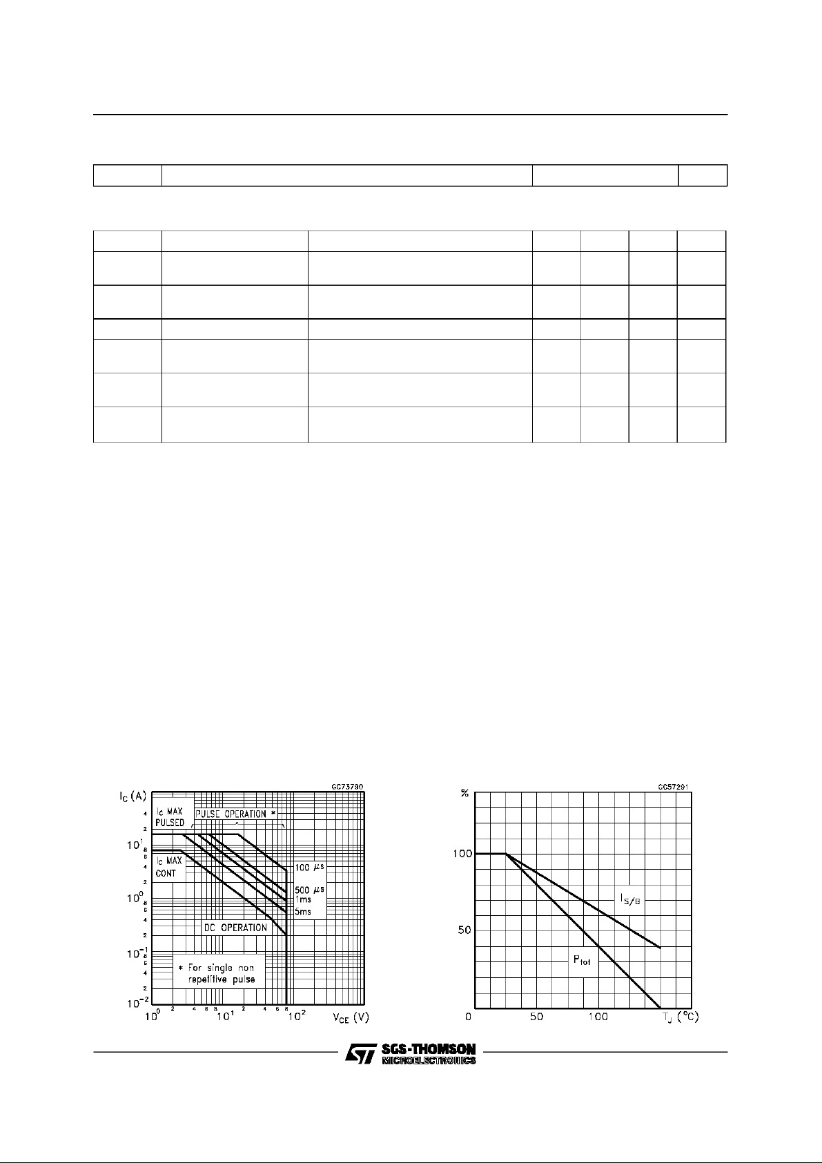
Safe OperatingArea DeratingCurves
2/5
Page 3

MJD44H11 / MJD45H11
DCCurrent Gain (NPNtype)
Collector-Emitter Saturation Voltage(NPN type)
DC Current Gain (PNP type)
Collector-EmitterSaturation Voltage (PNP type)
3/5
Page 4

MJD44H11 / MJD45H11
TO-252 (DPAK) MECHANICAL DATA
DIM.
mm inch
MIN. TYP. MAX. MIN. TYP. MAX.
A 2.2 2.4 0.086 0.094
A1 0.9 1.1 0.035 0.043
A2 0.03 0.23 0.001 0.009
B 0.64 0.9 0.025 0.035
B2 5.2 5.4 0.204 0.212
C 0.45 0.6 0.017 0.023
C2 0.48 0.6 0.019 0.023
D 6 6.2 0.236 0.244
E 6.4 6.6 0.252 0.260
G 4.4 4.6 0.173 0.181
H 9.35 10.1 0.368 0.397
L2 0.8 0.031
L4 0.6 1 0.023 0.039
4/5
H
A
E
C2
L2
B2
==
==
DETAIL”A”
D
2
13
L4
A1
C
A2
DETAIL”A”
B
G
==
0068772-B
Page 5

MJD44H11 / MJD45H11
Information furnished is believed to be accurate and reliable. However, SGS-THOMSON Microelectronics assumes no responsability for the
consequencesof use ofsuch information nor for any infringement of patentsor other rights of third parties which may resultsfrom its use. No
licenseis grantedby implicationor otherwise underany patentor patent rights of SGS-THOMSONMicroelectronics. Specificationsmentioned
in this publicationare subject to change without notice.This publication supersedes andreplaces all information previously supplied.
SGS-THOMSONMicroelectronics productsarenotauthorizedfor useascriticalcomponents in life supportdevices or systems withoutexpress
writtenapproval of SGS-THOMSON Microelectonics.
1997 SGS-THOMSONMicroelectronics- Printed in Italy - All Rights Reserved
Australia- Brazil - Canada - China - France - Germany - Italy - Japan - Korea - Malaysia- Malta- Morocco - The Netherlands-
Singapore- Spain- Sweden- Switzerland - Taiwan - Thailand - United Kingdom- U.S.A
SGS-THOMSONMicroelectronics GROUP OF COMPANIES
...
5/5
 Loading...