

Datasheet MIC5231-5.0BM5, MIC5231-2.75BM5, MIC5231-3.0BM5, MIC5231-3.3BM5 Datasheet (MICREL)
Page 1
MIC5231 Micrel
MIC5231
Micropower µCap LDO Regulator
Preliminary Information
General Description
The MIC5231 µCap low-dropout voltage regulator is intended
for low-output-current biasing applications. It features extremely low ground current, not greater than 4µA under all
load and temperature conditions, making it efficient and ideal
for keep-alive applications in devices such as notebook
computers.
The MIC5231 offers better than 2% initial accuracy and low
dropout (typically 150mV at 10mA output current). An output
capacitor is not required for stable operation, decreasing cost
and board space. Tiny ceramic chip capacitors may be used
to improve transient response.
The MIC5231 also features a control pin which allows the
regulator to be shut down when not required. Its shutdownstate draws zero current, benefitting battery-powered applications.
The MIC5231 is available in fixed output voltages of 2.75V,
3.0V, 3.3V and 5V in the small SOT-23-5 IttyBitty™ package.
Contact Micrel for other voltage options.
Features
• Extremely low quiescent current—
• No output capacitor requirement
• Stable with ceramic or tantalum capacitors
• IttyBitty™ SOT-23-5 surface-mount package
• 10mA output drive
• Low 150mV at 10mA dropout voltage
• Tight load and line regulation
• Low temperature coefficient
• Logic-level enable input
only 0.65µA
Applications
• Real time clocks
• SRAM backup
• Cellular telephones
• Laptop, notebook and palmtop computers
• Battery-powered equipment
• Bar code scanners
• SMPS post-regulator and dc-to-dc modules
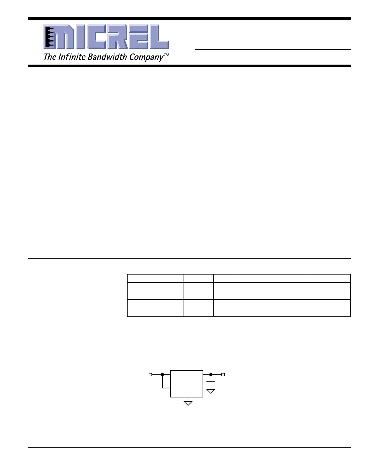
Typical Application
Ordering Information
Part Number Marking Voltage Temperature Range Package
MIC5231-2.75BM5 LM2H 2.75V –40°C to +125°C SOT-23-5
MIC5231-3.0BM5 LM30 3.0V –40°C to +125°C SOT-23-5
MIC5231-3.3BM5 LM33 3.3V –40°C to +125°C SOT-23-5
MIC5231-5.0BM5 LM50 5.0V –40°C to +125°C SOT-23-5
V
IN
6V
5V Linear Regulator Application
MIC5231-5.0BM5
IN
OUT
EN
GND
V
5V
OUT
IttyBitty is a trademark of Micrel, Inc.
MICREL INC. 1849 FORTUNE DRIVE SAN JOSE, CA 95131 USA TEL + 1 (408) 944-0800 FAX + 1 (408) 944-0970
June 2000 1 MIC5231
Page 2
MIC5231 Micrel
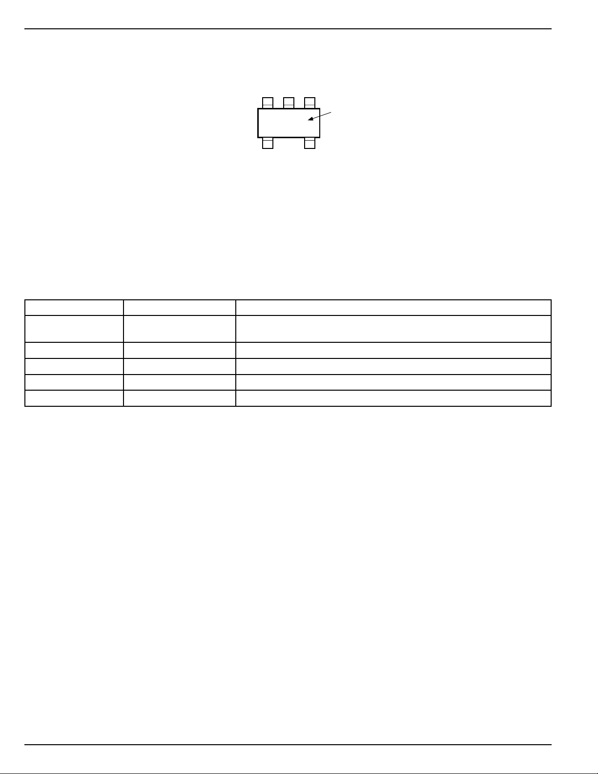
Pin Configuration
Pin Description
Pin Number Pin Name Pin Function
1 EN Enable (Input): Active high. Logic high = enable; logic low = shutdown. Do
2 GND Ground
3 IN Supply Input
4 OUT Regulated Output
5 NC not internally connected
GND
2
EN
IN
LM50
45
NCOUT
MIC5231-5.0BM5
not float.
13
Part
Identification
Absolute Maximum Ratings (Note 1)
Supply Voltage (VIN) .................................... –0.6V to +14V
Lead Temperature (soldering, 5 sec.) ....................... 260°C
Storage Temperature (TA) ....................... –60°C to +150°C
ESD, Note 3 .................................................................. 2kV
Operating Ratings (Note 2)
Input Voltage (VIN) ........................................... 3.5V to 12V
Ambient Temperature (TA) ......................... –40°C to +85°C
Junction Temperature (TJ) ....................... –40°C to +125°C
Thermal Resistance, Note 4
MIC5231 2 June 2000
Page 3
MIC5231 Micrel
Electrical Characteristics
VIN = V
Symbol Parameter Conditions Min Typ Max Units
V
OUT
∆V
OUT
∆V
OUT/VOUT
∆V
OUT/VOUT
V
DO
I
Q
PSRR Ripple Rejection f = 100Hz, IL = 100µA50dB
Enable Input
V
ENL
I
ENL
I
ENH
Note 1. Exceeding the absolute maximum rating may damage the device.
Note 2. The device is not guaranteed to function outside its operating rating.
Note 3. Devices are ESD sensitive. Handling precautions recommended.
Note 4: The maximum allowable power dissipation at any TA (ambient temperature) is P
Note 5: Output voltage temperature coefficient is defined as the worst case voltage change divided by the total temperature range.
Note 6: Regulation is measured at constant junction temperature using low duty cycle pulse testing.
Note 7: Dropout voltage is defined as the input to output differential at which the output voltage drops 2% below its nominal value measured at 1V
+ 1V; IL = 100µA; CL = 0.47µF; TJ = 25°C, bold values indicate –40°C ≤ TJ ≤ +125°C; unless noted.
OUT
Output Voltage Accuracy variation from nominal V
OUT
–2+2%
–3 +3 %
/∆T Output Voltage Note 5 250 ppm/°C
Temperature Coefficient
Line Regulation VIN = 6V to 12V 0.2 0.25 %
Load Regulation IL = 10µA to 10mA, Note 6 0.2 1 %
Dropout Voltage, Note 7 IL = 1mA 15 mV
IL = 10mA 150 300 mV
Ground Pin Current VIN = 6V, IL = 10mA 0.65 3 µA
VIN = 12V, IL = 10mA 1.1 4 µA
Enable Input Voltage VEN = logic low (regulator off) 0.4 0.18 V
VEN = logic high ((regulator on) 1.4 V
Enable Input Current V
Enable Input Current V
130°C/W. Mounted to a standard PC board, the θJA is approximately 235°C/W.
differential. For outputs below 3.5V, dropout voltage is the input-to-output differential with the minimum input voltage 3.5V. Minimum input
operating voltage is 3.5V.
≤ 0.18V (regulator off) 1 nA
ENL
≥ 1.4V (regulator on) 1 nA
ENH
D(max)
= (T
– TA) ÷ θJA. The θJC of the MIC5231 is
J(max)
June 2000 3 MIC5231
Page 4
MIC5231 Micrel
g
Ground Current
vs. Output Current
1
0.5
GROUND CURRENT (µA)
0
0110
OUTPUT CURRENT (mA)
Ground Current
3.10
3.05
3.00
2.95
OUTPUT VOLTAGE (V)
2.90
vs. Temperature
-50 -20 10 40 70 100 130
TEMPERATURE (°C)
Ground Current
vs. Supply Volta
0.8
0.7
0.6
0.5
0.4
Ground Current (µA)
0.3
0.2
24681012
Supply Voltage (V)
e
1
0.8
0.6
0.4
0.2
GROUND CURRENT (µA)
0
-40 0 40 80 120
Short Circuit Current
150
100
SHORT CIRCUIT CURRENT (mA)
vs. Temperature
50
0
-50 -20 10 40 70 100 130
TEMPERATURE (°C)
Ground Current
vs. Temperature
TEMPERATURE (°C)
MIC5231 4 June 2000
Page 5

MIC5231 Micrel
Block Diagram
IN OUT
EN
MIC5231
GND
Applications Information
Input Capacitor
A 0.1µF (or larger) capacitor should be placed from the IN
(supply input) to GND (ground) if there is more than 20 cm of
wire between IN and the ac filter capacitor or if supplied from
a battery.
Output Capacitors
The MIC5231 does not require an output capacitor for stability. A 1µF or larger capacitor is recommended between OUT
(output) and GND to improve the regulator’s transient response. A 0.1µF capacitor can be used to reduce overshoot
recovery time at the expense of overshoot amplitude. The
ESR (effective series resistance) of this capacitor has no
effect on regulator stability, but low-ESR capacitors improve
high frequency transient response. The value of this capacitor may be increased without limit, but values larger than
10µF tend to increase the settling time after a step change in
input voltage or output current.
The MIC5231 has no minimum load current; it will remain
stable and in regulation with no load (other than the internal
voltage divider). This is especially important in real-time clock
and CMOS RAM keep-alive applications.
Minimum Load Current
The MIC5231 does not require a minimum load for proper
operation. This allows the device to operate in applications
where very light output currents are required for keep-alive
purposes. This is important for powering SRAM or Flash
memory in low-power modes for handheld devices.
Bandgap
Reference
Safe Operating Conditions
The MIC5231 does not incorporate current limit or thermal
shutdown in the design. The output pass element is approximately 15 ohms, therefore, when a short occurs from the
output to ground, the current is self-limited. The pass element
has a positive temperature coefficient, such that when the
device gets hot, the output impedance goes up, limiting the
current even further. The maximum junction temperature for
the device is 125°C, and it is important that this is not
exceeded for any length of time.
Thermal Considerations
The MIC5231 is not intended for sourcing currents that would
cause a large power loss in the device, but since it is not
current limited, it is possible to source more than the rated
10mA. At this point, it is important to ensure that the die
temperature does not exceed 125°C.
Power dissipation in the regulator is calculated as follows:
PD = (VIN – V
OUT
)*I
OUT
+ VIN *I
GND
The MIC5231 consumes only 0.65uA over load and does not
need to consider that contribution in the power dissipation
equation, therefore the equation is simplified.
PD = (VIN – V
OUT
)*I
OUT
The MIC5231, in the IttyBitty SOT23-5 package, has a
thermal resistance, junction-to-ambient, of 235°C/W. Using
this number, the power dissipation capability of that package,
without exceeding a 125°C junction temperature rating, can
easily be calculated.
P
P
= (T
D(max)
= (125°C – Ta)/235°C/W
D(max)
j(max)
– Ta)/θ
JA
If the device is being operated at 85°C, the maximum power
June 2000 5 MIC5231
Page 6

MIC5231 Micrel
dissipation allowed can easily be determined.
P
P
= (125°C – 85°C)/235°C/W
D(max)
= 170mW
D(max)
Therefore, the device can only dissipate 170mW maximum.
If the MIC5231 is powered off of a 12V source and the output
voltage is 3.3V, the maximum output current can be calculated.
PD = (Vin - Vout)·Iout
170mW = (12V - 3.3V)·Iout
Iout = 170mW/8.7V
Iout = 19.5mA
Therefore, the device can source almost 20mA at an ambient
of 85°C before the die temperature exceeds 125°C.
MIC5231 6 June 2000
Page 7

MIC5231 Micrel
Package Information
1.90 (0.075) REF
0.95 (0.037) REF
3.02 (0.119)
2.80 (0.110)
0.50 (0.020)
0.35 (0.014)
1.75 (0.069)
1.50 (0.059)
1.30 (0.051)
0.90 (0.035)
0.15 (0.006)
0.00 (0.000)
3.00 (0.118)
2.60 (0.102)
SOT-23-5 (M5)
10°
0°
DIMENSIONS:
MM (INCH)
0.60 (0.024)
0.10 (0.004)
0.20 (0.008)
0.09 (0.004)
June 2000 7 MIC5231
Page 8

MIC5231 Micrel
MICREL INC. 1849 FORTUNE DRIVE SAN JOSE, CA 95131 USA
TEL + 1 (408) 944-0800 FAX + 1 (408) 944-0970
This information is believed to be accurate and reliable, however no responsibility is assumed by Micrel for its use nor for any infringement of patents or
other rights of third parties resulting from its use. No license is granted by implication or otherwise under any patent or patent right of Micrel Inc.
© 2000 Micrel Incorporated
MIC5231 8 June 2000
 Loading...