

Page 1
MIC5016/5017 Micrel
5-146 October 1998
Features
• 2.75V to 30V operation
• 100µA maximum supply current (5V supply)
•15µA typical off-state current
• Internal charge pump
• TTL compatible input
• Withstands 60V transient (load dump)
• Reverse battery protected to –20V
• Inductive spike protected to –20V
• Overvoltage shutdown at 35V
• Internal 15V gate protection
• Minimum external parts
• Operates in high-side or low-side configurations
•1µA control input pull-off
• Inverting and noninverting versions
Applications
• Automotive electrical load control
• Battery-powered computer power management
• Lamp control
• Heater control
• Motor control
• Power bus switching
Ordering Information
Part Number Temperature Range Package
Noninverting
MIC5016BWM –40°C to +85°C 16-pin Wide SOIC
MIC5016BN –40°C to +85°C 14-pin Plastic DIP
Inverting
MIC5017BWM –40°C to +85°C 16-pin Wide SOIC
MIC5017BN –40°C to +85°C 14-pin Plastic DIP
MIC5016/5017
Low-Cost Dual High- or Low-Side MOSFET Driver
T ypical Application
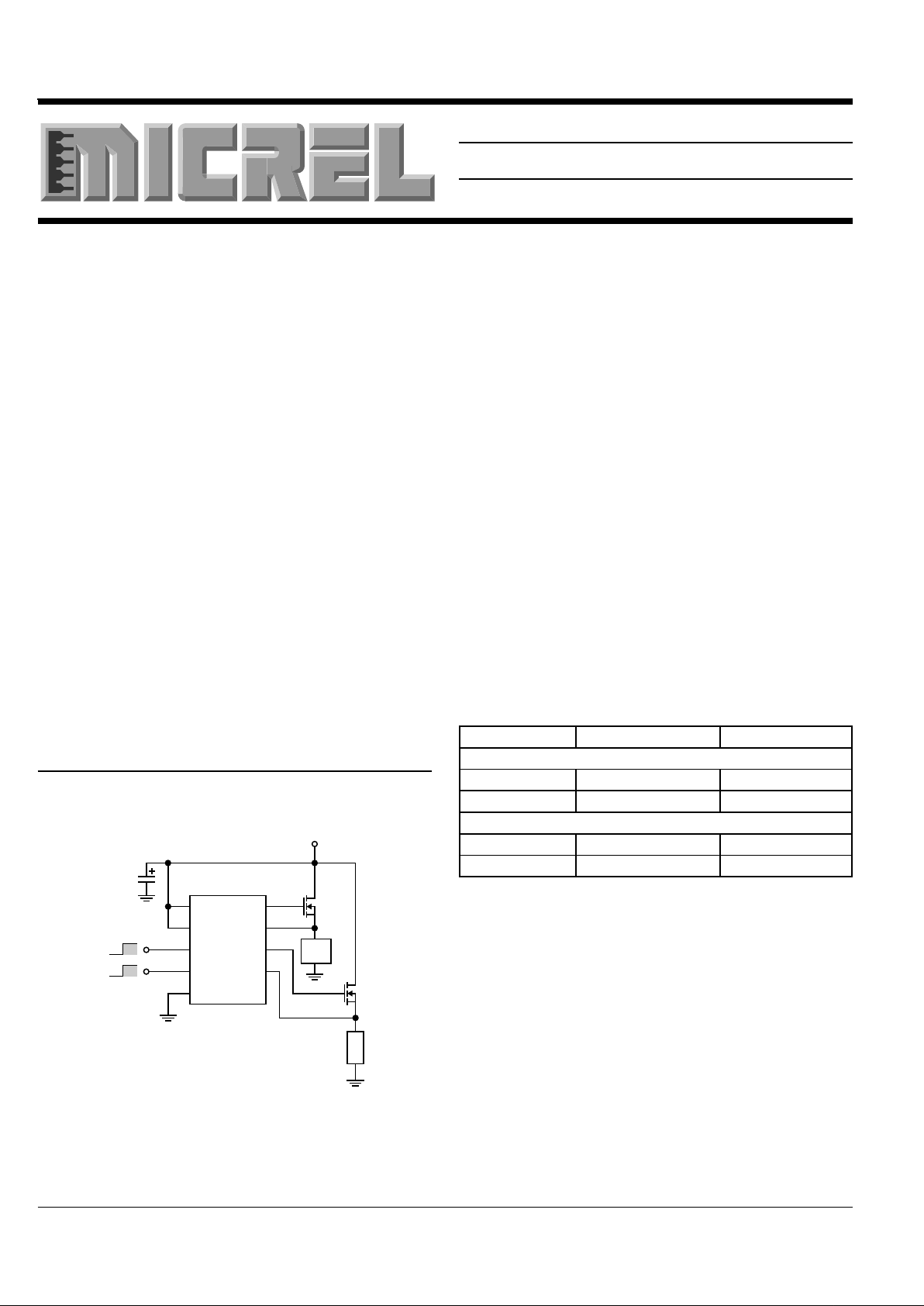
Figure 1: 3-Volt “Sleep-Mode” Switches
with Logic-Level MOSFETs
OFF
ON
MIC5016BN
IRLZ24
+3V to +4V
Gate A
Source B
Gnd
In A
V+ B
V+ A
Source A
Gate B
10µF
In B
Back
Light
IRLZ24
Logic
OFF
ON
General Description
MIC5016 and MIC5017 dual MOSFET drivers are designed
for gate control of N-channel, enhancement-mode, power
MOSFETs used as high-side or low-side switches. The
MIC5016/7 can sustain an on-state output indefinitely.
The MIC5016/7 operates from a 2.75V to 30V supply. In highside configurations, the driver can control MOSFETs that
switch loads of up to 30V. In low-side configurations, with
separate supplies, the maximum switched voltage is limited
only by the MOSFET.
The MIC5016/7 has two TTL compatible control inputs. The
MIC5016 is noninverting while the MIC5017 is inverting.
The MIC5016/7 features internal charge pumps that can
sustain gate voltages greater than the available supply
voltage. The driver is capable of turning on logic-level
MOSFETs from a 2.75V supply or standard MOSFETs from
a 5V supply. Gate-to-source output voltages are internally
limited to approximately 15V.
The MIC5016/7 is protected against automotive load dump,
reversed battery, and inductive load spikes of –20V. The
driver’s overvoltage shutdown feature turns off the external
MOSFETs at approximately 35V to protect the load against
power supply excursions.
The MIC5016 is an improved pin-for-pin compatible replacement in many MIC5012 applications.
The MIC5016/7 is available in plastic 14-pin DIP and 16-pin
SOIC pacakges.
Page 2
MIC5016/5017 Micrel
October 1998 5-147
5
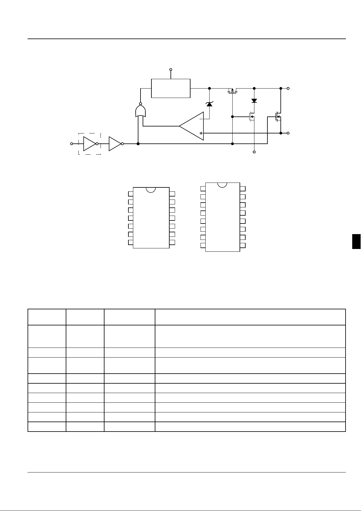
Block Diagram 1 of 2 Drivers per Package
Charge Pump
V+
*
Input
Ground
Source
Gate
15V
* Inverting version only
Connection Diagram
16-pin Wide SOIC14-pin DIP
2
3
4
5
6
7
1
13
12
11
10
9
8
14
NC
Source A
Gnd
Gate A
Source B
Gate B
NC
NC
NC
V+ B
In B
V+ A
NC
In A
N, J
2
3
4
5
6
7
8
1
15
14
13
12
11
10
9
16
NC
Source A
Gnd
Gate A
Source B
Gate B
NC
NC
NC
NC
NC
V+ B
In B
V+ A
NC
In A
WM
Pin Description
Pin Number Pin Number Pin Name Pin Function
N, J Package WM Package
12 14 V
+
A Supply Pin A. Must be decoupled to isolate large transients caused by power
MOSFET drain. 10µF is recommended close to pins 12 and/or 10 and
ground. V+A and V+B may be connected to separate supplies.
10 12 V+B Supply Pin B. See V+A.
14 16 Input A Turns on power MOSFET A when asserted. Requires approximately 1µA to
switch.
11 13 Input B Turns on power MOSFET B. See Input A.
4 4 Gate A Drives and clamps the gate of power MOSFET A
6 6 Gate B Drives and clamps the gate of power MOSFET B
2 2 Source A Connects the source lead of MOSFET A
5 5 Source B Connects the source lead of MOSFET B
3 3 Gnd Ground
Page 3

MIC5016/5017 Micrel
5-148 October 1998
Parameter Conditions Min Typ Max Units
Supply Current V+ = 30V V
IN
De-Asserted (Note 5) 10 25 µA
(Each Driver Channel) V
IN
Asserted (Note 5) 5.0 10 mA
V+ = 5V V
IN
De-Asserted 10 25
µA
V
IN
Asserted 60 100
V+ = 3V V
IN
De-Asserted 10 25
µA
V
IN
Asserted 25 35
Logic Input Voltage Threshold 3.0V ≤ V+ ≤ 30V Digital Low Level 0.8
V
IN
T
A
= 25°C Digital High Level 2.0
V
Logic Input Current 3.0V ≤ V+ ≤ 30V V
IN
Low –2.0 0
µA
MIC5016 (non-inverting) V
IN
High 1.0 2.0
Logic Input Current 3.0V ≤ V+ ≤ 30V V
IN
Low –2.0 –1.0
µA
MIC5017 (inverting) V
IN
High –1.0 2.0
Input Capacitance 5.0 pF
Gate Enhancement 3.0V ≤ V+ ≤ 30V V
IN
Asserted 4.0 17 V
V
GATE
- V
SUPPLY
Zener Clamp 8.0V ≤ V+ ≤ 30V V
IN
Asserted 13 15 17 V
V
GATE
- V
SOURCE
Gate Turn-on Time, t
ON
V+ = 4.5V V
IN
switched on, measure 2.5 8.0 ms
(Note 4) CL = 1000pF time for V
GATE
to reach V+ + 4V
V+ = 12V As above, measure time for 90 140 µs
CL = 1000pF V
GATE
to reach V+ + 4V
Gate Turn-off Time, t
OFF
V+ = 4.5V V
IN
switched off, measure 6.0 30 µs
(Note 4) CL = 1000pF time for V
GATE
to reach 1V
V+ = 12V As above, measure time for 6.0 30 µs
CL = 1000pF V
GATE
to reach 1V
Overvoltage Shutdown 35 37 41 V
Threshold
Electrical Characteristics (Note 3) T
A
= –55°C to +125°C unless otherwise specified
Note 1: Absolute Maximum Ratings indicate limits beyond which damage to the device may occur. Electrical specifications do not apply
when operating the device beyond its specified Operating Ratings.
Note 2: The MIC5016/5017 is ESD sensitive.
Note 3: Minimum and maximum Electrical Characteristics are 100% tested at TA = 25°C and TA = 85°C, and 100% guaranteed over the
entire operating temperature range. Typicals are characterized at 25°C and represent the most likely parametric norm.
Note 4: Test conditions reflect worst case high-side driver performance. Low-side and bootstrapped topologies are significantly faster—see
Applications Information. Maximum value of switching time seen at 125°C, unit operated at room temperature will reflect the typical value
shown.
Note 5: “Asserted” refers to a logic high on the MIC5016 and a logic low on the MIC5017.
Absolute Maximum Ratings (Notes 1,2) Operating Ratings (Notes 1,2)
θJA (Plastic DIP).....................................................140°C/W
θ
JA
(SOIC) .............................................................110°C/W
Ambient Temperature: B version ................–40°C to +85°C
Ambient Temperature: A version ............. +55°C to +125°C
Storage Temperature ................................–65°C to +150°C
Lead Temperature......................................................260°C
(max soldering time: 10 seconds)
Supply Voltage (V+) ......................................... 2.75V to 30V
Supply Voltage ...............................................–20V to 60V
Input Voltage .....................................................–20V to V
+
Source Voltage..................................................–20V to V
+
Source Current..........................................................50mA
Gate Voltage ..................................................–20V to 50V
Junction Temperature .............................................. 150°C
Page 4
MIC5016/5017 Micrel
October 1998 5-149
5
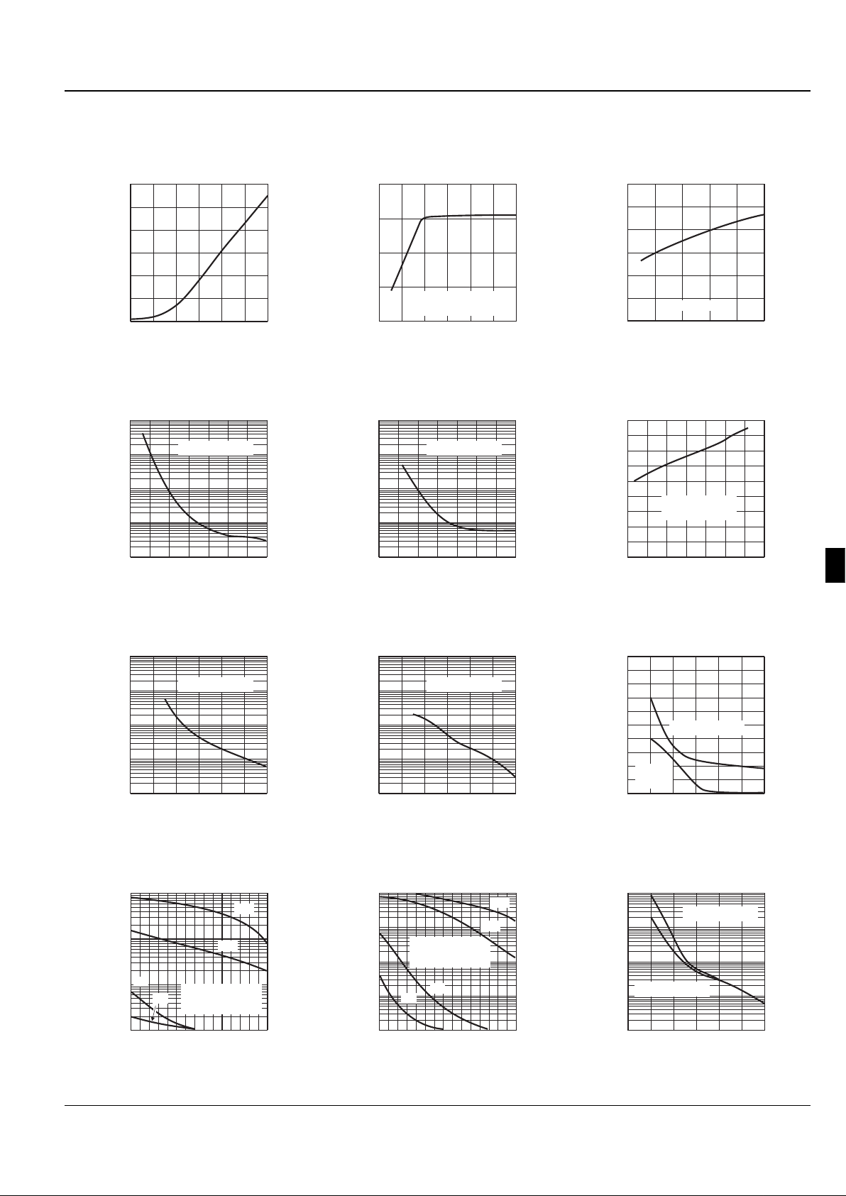
Typical Characteristics All data measured using FET probe to minimize resistive loading
0
1
2
3
4
5
6
0 5 10 15 20 25 30
SUPPLY CURRENT (mA)
SUPPLY VOLTAGE (V)
Supply Current per Channel
(Output Asserted)
0
5
10
15
20
0 5 10 15 20 25 30
GATE ENHANCEMENT (V)
SUPPLY VOLTAGE (V)
Gate Enhancement
vs. Supply Voltage
Gate Enhancement =
V
GATE
– V
SUPPLY
0
50
100
150
200
250
300
0246810
TURN-ON TIME (µs)
GATE CAPACITANCE (nF)
High-Side Turn-On Time
vs. Gate Capacitance
Supply = 12V
0.01
0.1
1
10
100
0 4 8 12 16 20 24 28
TURN-ON TIME (ms)
SUPPLY VOLTAGE (V)
High-Side Turn-On Time
Until Gate = Supply + 4V
C
GATE
= 1300pF
0.01
0.1
1
10
100
0 4 8 12 16 20 24 28
TURN-ON TIME (ms)
SUPPLY VOLTAGE (V)
High-Side Turn-On Time
Until Gate = Supply + 4V
C
GATE
= 3000pF
0
20
40
60
80
100
120
140
160
180
-60 -30 0 30 60 90 120 150
HIGH-SIDE TURN-ON TIME (µs)
AMBIENT TEMPERATURE (°C)
High-Side Turn-On Time
vs. Temperature
Supply = 12V
C
GATE
= 1000pF
0.01
0.1
1
10
100
0 5 10 15 20 25 30
TURN-ON TIME (ms)
SUPPLY VOLTAGE (V)
High-Side Turn-On Time
Until Gate = Supply + 10V
C
GATE
= 1300pF
0.01
0.1
1
10
100
0 5 10 15 20 25 30
TURN-ON TIME (ms)
SUPPLY VOLTAGE (V)
High-Side Turn-On Time
Until Gate = Supply + 10V
C
GATE
= 3000pF
0
2
4
6
8
10
0 5 10 15 20 25 30
TURN-OFF TIME (µs)
SUPPLY VOLTAGE (V)
High-Side Turn-Off Time
Until Gate = 1V
C
GATE
= 3000pF
C
GATE
=
1300pF
1
10
100
1000
0 5 10 15
OUTPUT CURRENT (µA)
GATE-TO-SOURCE VOLTAGE (V)
Charge-Pump
Output Current
Source connected
to supply: supply
voltage as noted
3V
5V
12V
28V
1
10
100
1000
10000
0 5 10 15
OUTPUT CURRENT (µA)
GATE-TO-SOURCE VOLTAGE (V)
Charge-Pump
Output Current
Source connected
to ground: supply
voltage as noted
3V
5V
12V
28V
1
10
100
1000
10000
0 5 10 15 20 25 30
TURN-ON TIME (µs)
SUPPLY VOLTAGE (V)
Low-Side Turn-On Time
Until Gate = 4V
C
GATE
= 3000pF
C
GATE
= 1300pF
Page 5
MIC5016/5017 Micrel
5-150 October 1998
Applications Information
Functional Description
The MIC5016 is functionally compatible with the MIC5012,
and the MIC5017 is an inverting configuration of the MIC5016.
The internal functions of these devices are controlled via a
logic block (refer to block diagram) connected to the control
input (pin 14). When the input is off (low for the MIC5016, and
high for the MIC5017), all functions are turned off, and the
gate of the external power MOSFET is held low via two Nchannel switches. This results in a very low standby current;
15µA typical, which is necessary to power an internal bandgap.
When the input is driven to the “ON” state, the N-channel
switches are turned off, the charge pump is turned on, and the
P-channel switch between the charge pump and the gate
turns on, allowing the gate of the power FET to be charged.
The op amp and internal zener form an active regulator which
shuts off the charge pump when the gate voltage is high
enough. This is a feature not found on the MIC5012.
The charge pump incorporates a 100kHz oscillator and onchip pump capacitors capable of charging a 1,000pF load in
90µs typical. In addition to providing active regulation, the
internal 15V zener is included to prevent exceeding the V
GS
rating of the power MOSFET at high supply voltages.
The MIC5016/17 devices have been improved for greater
ruggedness and durability. All pins can withstand being
pulled 20 V below ground without sustaining damage, and the
supply pin can withstand an overvoltage transient of 60V for
1s. An overvoltage shutdown has also been included, which
turns off the device when the supply reaches 35V.
Construction Hints
High current pulse circuits demand equipment and assembly
techniques that are more stringent than normal, low current
lab practices. The following are the sources of pitfalls most
often encountered during prototyping:
Supplies
: Many bench
power supplies have poor transient response. Circuits that
are being pulse tested, or those that operate by pulse-width
modulation will produce strange results when used with a
supply that has poor ripple rejection, or a peaked transient
response. Always monitor the power supply voltage that
appears at the drain of a high side driver (or the supply side
of the load for a low side driver) with an oscilloscope. It is not
uncommon to find bench power supplies in the 1kW class that
overshoot or undershoot by as much as 50% when pulse
loaded. Not only will the load current and voltage measurements be affected, but it is possible to overstress various
components, especially electrolytic capacitors, with possibly
catastrophic results. A 10µF supply bypass capacitor
at the
chip is
recommended.
Residual resistances
: Resistances in
circuit connections may also cause confusing results. For
example, a circuit may employ a 50mΩ power MOSFET for
low voltage drop, but unless careful construction techniques
are used, one could easily add 50 to 100mΩ resistance. Do
not use a socket for the MOSFET. If the MOSFET is a TO220 type package, make high current connections to the
drain tab.Wiring
losses have a profound effect on high-current circuits. A
floating milliohmeter can identify connections that are contributing excess drop under load.
Low Voltage Testing As the MIC5016/5017 have relatively
high output impedances, a normal oscilloscope probe will
load the device. This is especially pronounced at low voltage
operation. It is recommended that a FET probe or unity gain
buffer be used for all testing.
Circuit Topologies
The MIC5016 and MIC5017 are well suited for use with
standard power MOSFETs in both low and high side driver
configurations. In addition, the lowered supply voltage requirements of these devices make them ideal for use with
logic level FETs in high side applications with a supply
voltage of 3V to 4V. (If higher supply voltages [>4V] are used
with logic level FETs, an external zener clamp must be
supplied to ensure that the maximum V
GS
rating of the logic
FET [10V] is not exceeded). In addition, a standard IGBT can
be driven using these devices.
Choice of one topology over another is usually based on
speed vs. safety. The fastest topology is the low side driver,
however, it is not usually considered as safe as high side
driving as it is easier to accidentally short a load to ground
than to V
CC.
The slowest, but safest topology is the high side
driver; with speed being inversely proportional to supply
voltage. It is the preferred topology for most military and
automotive applications. Speed can be improved considerably by bootstrapping the supply.
All topologies implemented using these devices are well
suited to driving inductive loads, as either the gate or the
source pin can be pulled 20V below ground with no effect.
External clamp diodes are unnecessary, except for the case
in which a transient may exceed the overvoltage trip point.
High Side Driver (Figure 1) The high side topology shown
here is an implementation of a “sleep-mode” switch for a
laptop or notebook computer which uses a logic level FET. A
standard power FET can easily be substituted when supply
voltages above 4V are required.
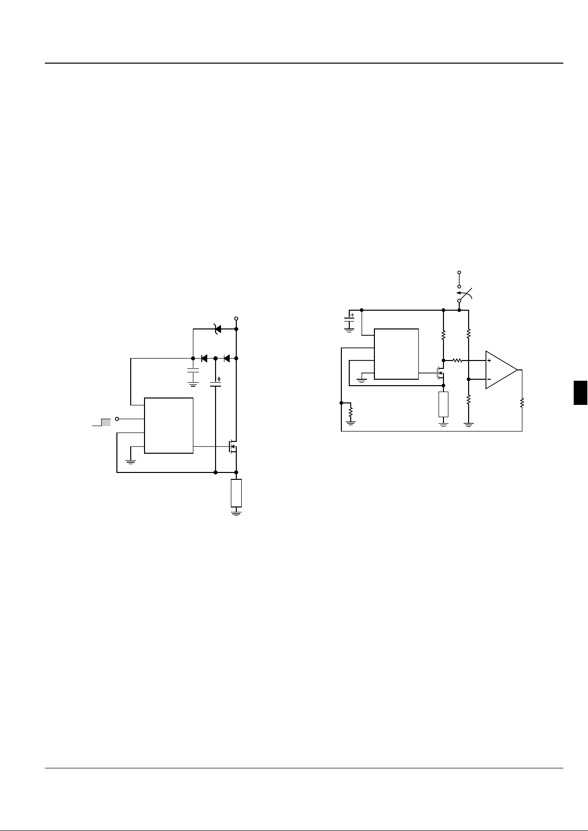
Low Side Driver (Figure 2) A key advantage of this topology,
as previously mentioned, is speed. The MOSFET gate is
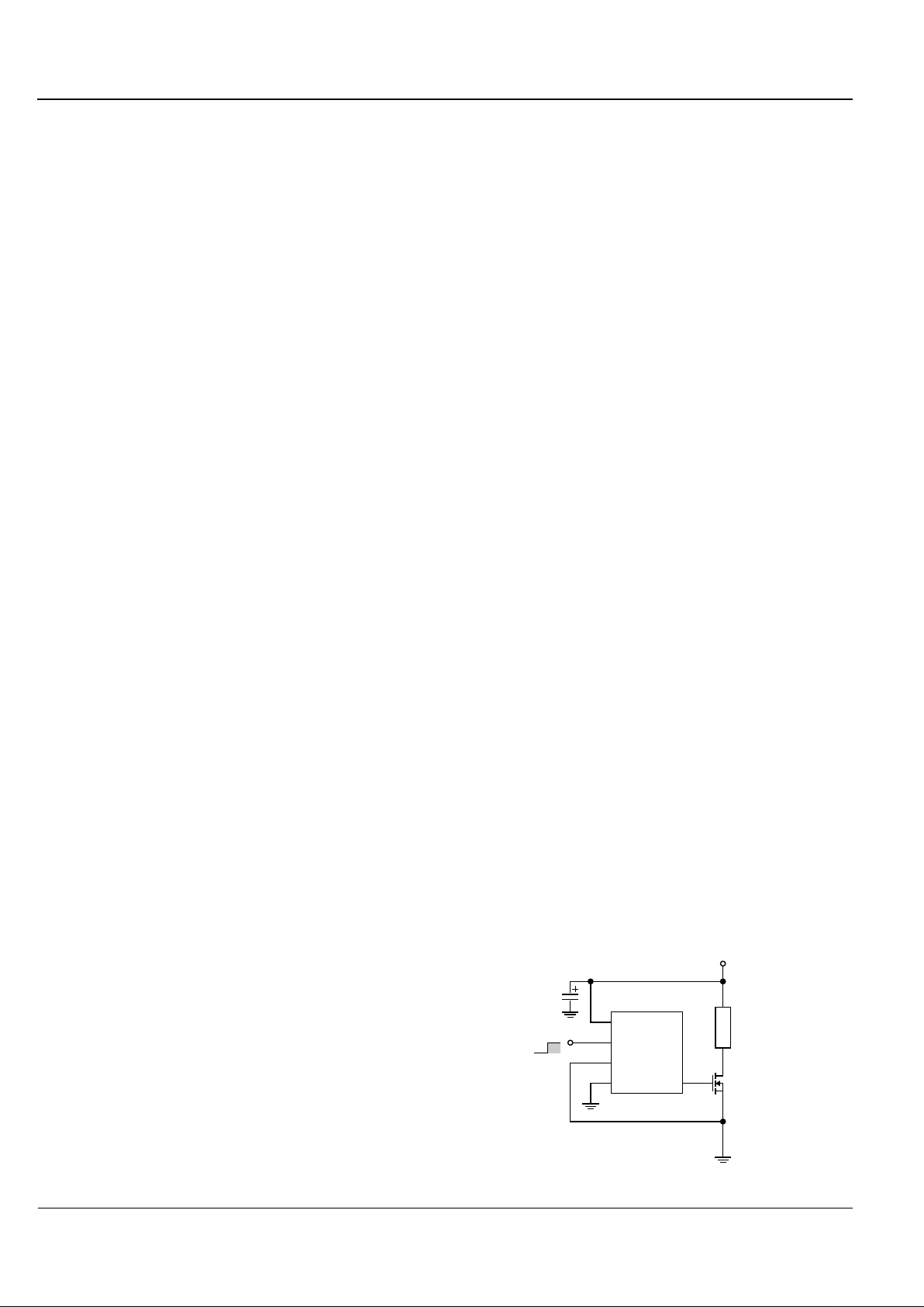
Figure 2. Low Side Driver
Load
1/2 MIC5016
OFF
ON
+3V to +30V
GateGnd
Source
Input
V+
10µF
Page 6
MIC5016/5017 Micrel
October 1998 5-151
5
driven to near supply immediately when the MIC5016/17 is
turned on. Typical circuits reach full enhancement in 50µs or
less with a 15V supply.
Bootstrapped High Side Driver (Figure 3) The turn-on time
of a high side driver can be improved to faster than 40µs by
bootstrapping the supply with the MOSFET source. The
Schottky barrier diode prevents the supply pin from dropping
more than 200mV below the drain supply, and improves turnon time. Since the supply current in the “OFF” state is only a
small leakage, the 100nF bypass capacitor tends to remain
charged for several seconds after the MIC5016/17 is turned
off. Faster switching speeds can be obtained at the expense
of supply voltage (the overvoltage shutdown will turn the part
off when the bootstrapping action pulls the supply pin above
35V) by using a larger capacitor at the junction of the two
1N4001 diodes. In a PWM application (this circuit can be
used for either PWM’ed or continuously energized loads), the
chip supply is sustained at a higher potential than the system
supply, which improves switching time.
Figure 3. Bootstrapped High-Side Driver
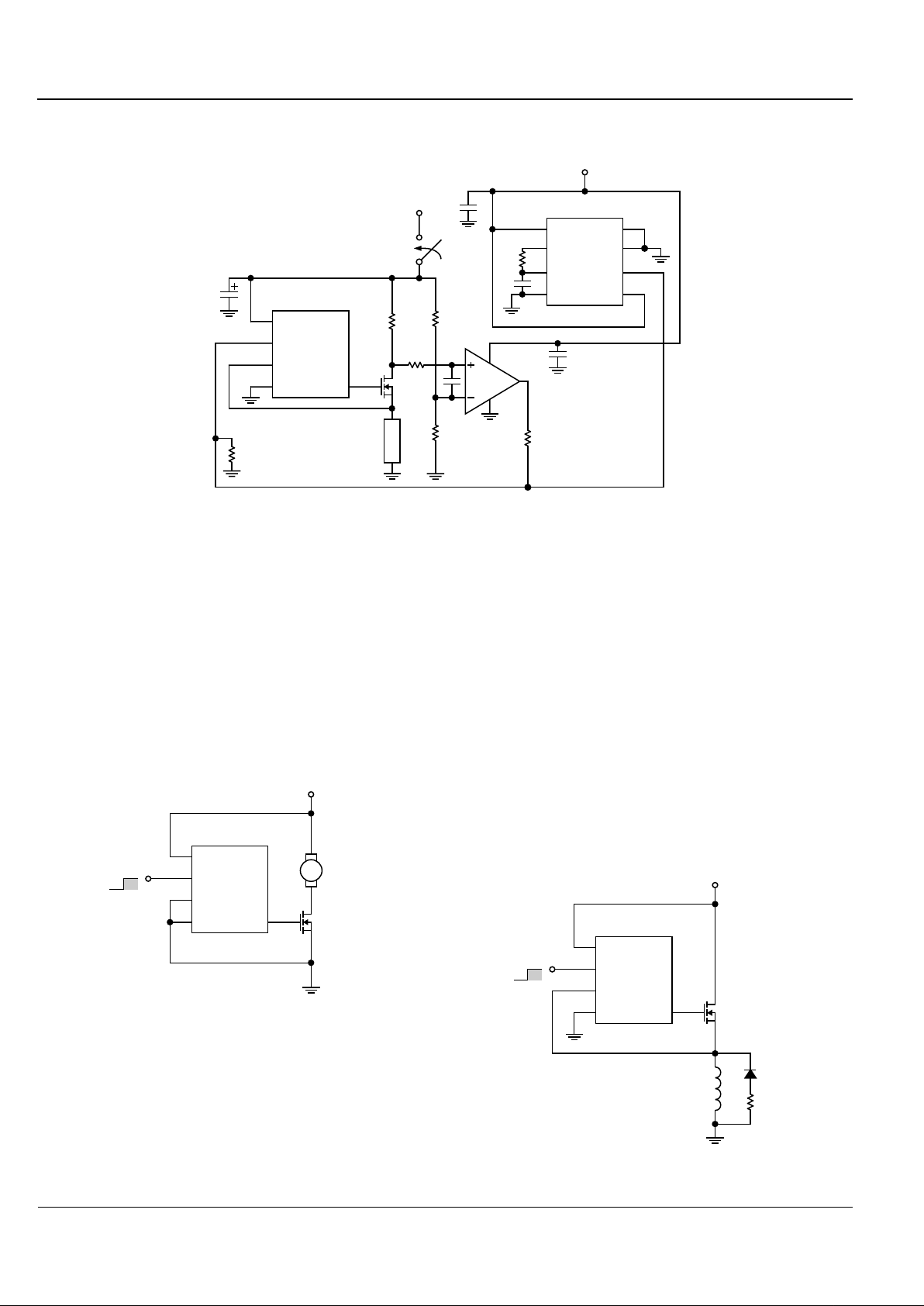
High Side Driver With Current Sense (Figure 4) Although no
current sense function is included on the MIC5016/17 devices, a simple current sense function can be realized via the
addition of one more active component; an LM301A op amp
used as a comparator. The positive rail of the op amp is tied
to V+, and the negative rail is tied to ground. This op amp was
chosen as it can withstand having input transients that swing
below the negative rail, and has common mode range almost
to the positive rail.
The inverting side of this comparator is tied to a voltage divider
which sets the voltage to V+ – V
TRIP
. The noninverting side
is tied to the node between the drain of the FET and the sense
resistor. If the overcurrent trip point is not exceeded , this node
will always be above V+ – V
TRIP
, and the output of the comparator will be high which feeds the control input of the MIC5016
(polarities should be reversed if the MIC5017 is used). Once
the overcurrent trip point has been reached, the comparator
Load
1/2 MIC5016
Control Input
OFF
ON
+2.75V to +30V
GateGnd
Source
Input
V+
1µF
100nF
1N4001 (2)
1N5817
IRF540
will go low, which shuts off the MIC5016. When the short is
removed, feedback to the input pin insures that the MIC5016
will turn back on. This output can also be level shifted and sent
to an I/O port of a microcontroller for intelligent control.
Current Shunts (RS). Low valued resistors are necessary for
use at RS. Resistors are available with values ranging from 1
to 50mΩ, at 2 to10W. If a precise overcurrent trip point is not
necessary, then a nonprecision resistor or even a measured
PCB trace can serve as RS. The major cause of drift in resistor
values with such resistors is temperature coefficient; the
designer should be aware that a linear, 500ppm/°C change
will contribute as much as 10% shift in the overcurrent trip
point.
If this is not acceptable, a power resistor designed for current
shunt service (drifts less than 100ppm/°C), or a Kelvin-sensed
resistor may be used.
†
Load
1/2 MIC5016
GateGnd
Source
Input
V+
10µF
R4
1kΩ
R
S
0.06Ω
12V
On
R1
1kΩ
R2
120kΩ
LM301A
2.2kΩ
I
TRIP
= V
TRIP/RS
= 1.7A
V
TRIP
= R1/(R1+R2)
Figure 4. High Side Driver with Overcurrent Shutdown
† Suppliers of Precision Power Resistors:
Dale Electronics, Inc., 2064 12th Ave., Columbus, NE 68601. (402) 565-3131
International Resistive Co., P.O. Box 1860, Boone,NC 28607-1860.
(704) 264-8861
Isotek Corp., 566 Wilbur Ave. Swansea, MA 02777. (508) 673-2900
Kelvin, 14724 Ventura Blvd., Ste. 1003, Sherman Oaks, CA 91403-3501.
(818) 990-1192
RCD Components, Inc., 520 E. Industrial Pk. Dr., Manchester, NH 03103.
(603) 669-0054
Ultronix, Inc., P.O. Box 1090, Grand Junction, CO 81502 (303) 242-0810
High Side Driver With Delayed Current Sense (Figure 5)
Delay of the overcurrent detection to accomodate high inrush
loads such as incandescent or halogen lamps can be accomplished by adding an LM3905 timer as a one shot to provide
an open collector pulldown for the comparator output such
that the control input of the MIC5017 stays low for a preset
amount of time without interference from the current sense
circuitry. Note that an MIC5017 must be used in this application (figure 5), as an inverting control input is necessary. The
delay time is set by the RC time constant of the external
components on pins 3 and 4 of the timer; in this case, 6ms was
chosen.
An LM3905 timer was used instead of a 555 as it provides a
clean transition, and is almost impossible to make oscillate.
Good bypassing and noise immunity is essential in this circuit
to prevent spurious op amp oscillations.
Page 7
MIC5016/5017 Micrel
5-152 October 1998
1/2 MIC5016
OFF
ON
IRFZ40
24V
GateGnd
Source
Input
V+
5kΩ
1N4005
ASCO
8320A
Solenoid
Typical Applications
Variable Supply Low Side Driver for Motor Speed Control
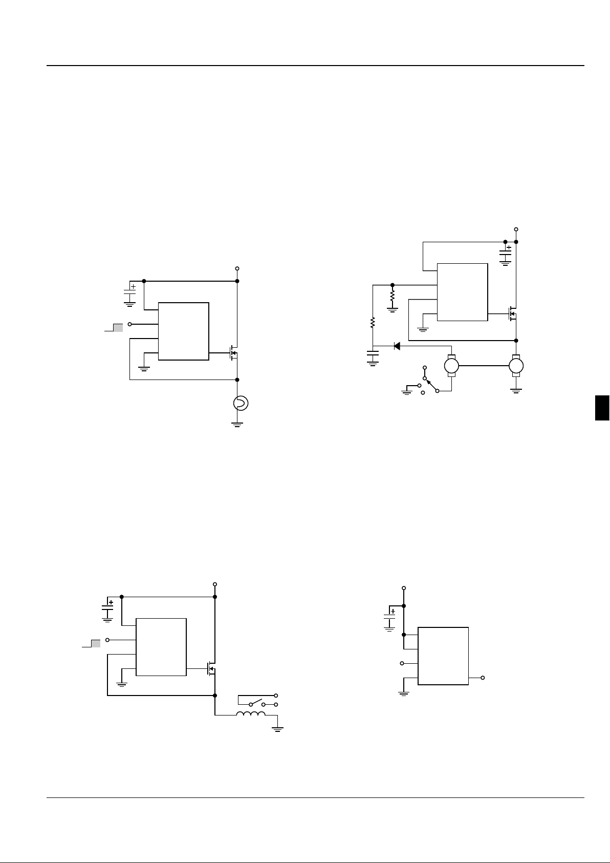
(Figure 6) The internal regulation in the MIC5016/17 allows
a steady gate enhancement to be supplied while the MIC5016/
17 supply varies from 5V to 30V, without damaging the
internal gate to source zener clamp. This allows the speed of
the DC motor shown to be varied by varying the supply
voltage.
Figure 6: DC Motor Speed Control/Driver
Solenoid Valve Driver (Figure 7) High power solenoid valves
are used in many industrial applications requiring the timed
dispensing of chemicals or gases. When the solenoid is
activated, the valve opens (or closes), releasing (or stopping)
fluid flow. A solenoid valve, like all inductive loads, has a
considerable “kickback” voltage when turned off, as current
cannot change instantaneously through an inductor. In most
applications, it is acceptable to allow this voltage to momentarily turn the MOSFET back on as a way of dissipating the
inductor's current. However, if this occurs when driving a
solenoid valve with a fast switching speed, chemicals or
gases may inadvertantly be dispensed at the wrong time with
possibly disasterous consequences. Also, too large of a
kickback voltage (as is found in larger solenoids) can damage
the MIC5016 or the power FET by forcing the Source node
below ground (the MIC5016 can be driven up to 20V below
ground before this happens). A catch diode has been
included in this design to provide an alternate route for the
inductive kickback current to flow. The 5kΩ resistor in series
with this diode has been included to set the recovery time of
the solenoid valve.
Figure 7: Solenoid Valve Driver
Figure 5. High Side Driver with Delayed Overcurrent Shutdown
Load
1/2 MIC5017
GateGnd
Source
Input
V+
10µF
R4
1kΩ
R
S
0.06Ω
12V
On
R1
1kΩ
R2
120kΩ
LM301A
2.2kΩ
0.01µF
LM3905N
1
2
3
4
8
7
6
5
Logic
V+Gnd
R/C
V
REF
Trigger
Emit
Coll
12V
1000pF
1kΩ
1/2 MIC5017
OFF
ON
IRF540
V
CC
= +5V to +30V
GateGnd
Source
Input
V+
M
Page 8
MIC5016/5017 Micrel
October 1998 5-153
5
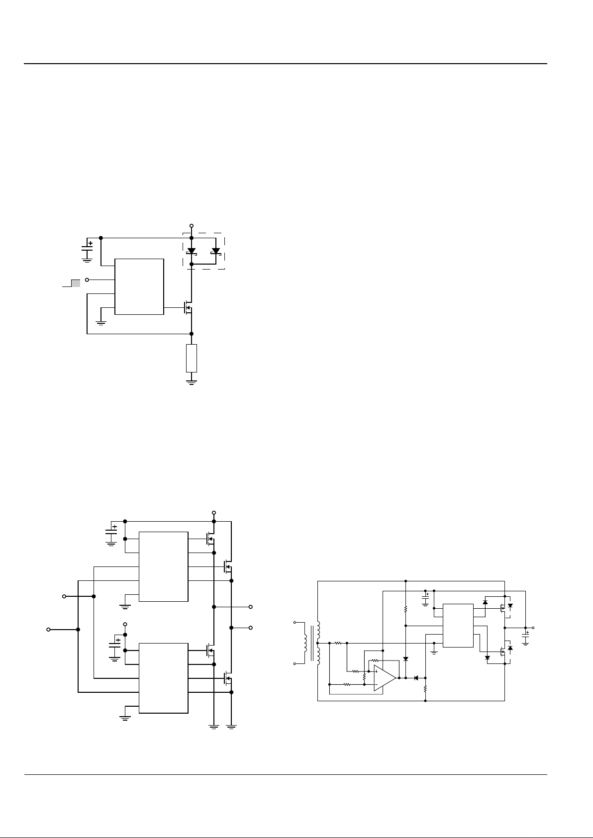
Motor Driver With Stall Shutdown (Figure 10) Tachometer
feedback can be used to shut down a motor driver circuit when
a stall condition occurs. The control switch is a 3-way type; the
“START” position is momentary and forces the driver ON.
When released, the switch returns to the “RUN” position, and
the tachometer’s output is used to hold the MIC5016 input ON.
If the motor slows down, the tach output is reduced, and the
MIC5016 switches OFF. Resistor “R” sets the shutdown
threshold.
Figure 10. Motor Stall Shutdown
Simple DC-DC Converter (Figure 11) The simplest applica-
tion for the MIC5016 is as a basic one-chip DC-DC converter.
As the output (Gate) pin has a relatively high impedance, the
output voltage shown will vary significantly with applied load.
Incandescent/Halogen Lamp Driver (Figure 8) The combi-
nation of an MIC5016/5017 and a power FET makes an
effective driver for a standard incandescent or halogen lamp
load. Such loads often have high inrush currents, as the
resistance of a cold filament is less than one-tenth as much as
when it is hot. Power MOSFETs are well suited to this
application as they have wider safe operating areas than do
power bipolar transistors. It is important to check the SOA
curve on the data sheet of the power FET to be used against
the estimated or measured inrush current of the lamp in
question prior to prototyping to prevent “explosive” results.
If overcurrent sense is to be used, first measure the duration
of the inrush, then use the topology of Figure 5 with the RC of
the timer chosen to accomodate the duration with suitable
guardbanding.
Figure 8: Halogen Lamp Driver
Relay Driver (Figure 9) Some power relay applications re-
quire the use of a separate switch or drive control, such as in
the case of microprocessor control of banks of relays where
a logic level control signal is used, or for drive of relays with
high power requirements. The combination of an MIC5016/
5017 and a power FET also provides an elegant solution to
power relay drive.
Figure 9: Relay Driver
Figure 11. DC - DC Converter
1/2 MIC5016
Control Input
OFF
ON
IRF540
12V
GateGnd
Source
Input
V+
10µF
OSRAM
HLX64623
1/2 MIC5016
Control Input
OFF
ON
IRF540
12V
GateGnd
Source
Input
V+
10µF
Guardian Electric
1725-1C-12D
1/2 MIC5016
GateGnd
Source
Input
V+
10µF
5V
V
OUT
= 12V
1/2 MIC5016
IRFZ44
12V
GateGnd
Source
Input
V+
10µF
MT
R
330kΩ
330kΩ
1N4148
Page 9
MIC5016/5017 Micrel
5-154 October 1998
High Side Driver With Load Protection (Figure 12) Although the MIC5016/17 devices are reverse battery protected, the load and power FET are not in a typical high side
configuration. In the event of a reverse battery condition, the
internal body diode of the power FET will be forward biased.
This allows the reversed supply to drive the load.
An MBR2035CT dual Schottky diode was used to eliminate
this problem. This particular diode can handle 20A continuous current and 150A peak current; therefore it should survive
the rigors of an automotive environment. The diodes are
paralleled to reduce the switch loss (forward voltage drop).
Figure 12: High Side Driver WIth Load Protection
Push-Pull Driver With No Cross-Conduction (Figure 13)
As the turn-off time of the MIC5016/17 devices is much faster
than the turn-on time, a simple dual push-pull driver with no
cross conduction can be made using one MIC5016 and one
MIC5017. The same control signal is applied to both inputs;
the MIC5016 turns on with the positive signal, and the
MIC5017 turns on when it swings low.
Figure 13: Push-Pull Driver
This scheme works with no additional components as the
relative time difference between the rise and fall times of the
MIC5014 is large. However, this does mean that there is
considerable deadtime (time when neither driver is turned
on). If this circuit is used to drive an inductive load, catch
diodes must be used on each half to provide an alternate path
for the kickback current that will flow during this deadtime.
This circuit is also a simple H-bridge which can be driven with
a PWM signal on the input for SMPS or motor drive applications in which high switching frequencies are not desired.
Synchronous Rectifier (Figure 14) In applications where
efficiency in terms of low forward voltage drops and low diode
reverse-recovery losses is critical, power FETs are used to
achieve rectification instead of a conventional diode bridge.
Here, the power FETs are used in the third quadrant of the IV
characteristic curve (FETs are installed essentially “backwards”). The two FETs are connected such that the top FET
turns on with the positive going AC cycle, and turns off when
it swings negative. The bottom FET operates opposite to the
top FET.
In the first quadrant of operation, the limitation of the device
is determined by breakdown voltage. Here, we are limited by
the turn-on of a parasitic p-n body drain diode. If it is allowed
to conduct, its reverse recovery time will crowbar the other
power FET and possibly destroy it. The way to prevent this
is to keep the IR drop across the device below the cut-in
voltage of this diode; this is accomplished here by using a fast
comparator to sense this voltage and feed the appropriate
signal to the control inputs of the MIC5016 device. Obviously,
it is very important to use a comparator with a fast slew rate
such as the LM393, and fast recovery diodes. 3mV of positive
feedback is used on the comparator to prevent oscillations.
At 3A, with an R
DS
(ON) of 0.077Ω, our forward voltage drop
per FET is ~ 0.2 V as opposed to the 0.7 to 0.8 V drop that a
normal diode would have. Even greater savings can be had
by using FETs with lower RDS(ON)s, but care must be taken
that the peak currents and voltages do not exceed the SOA
of the chosen FET.
Figure 14: High Efficiency 60 Hz
Synchronous Rectifier
Load
1/2 MIC5016
Control Input
OFF
ON
IRF540
12V
NC
GateGnd
Source
Input
V+
NC
NC
10µF
MBR2035CT
MIC5016
Control Input 1
12
10
3
11
IRFZ40
12V
Gate A
Source B
Gnd
In B
In A
V+ A
Source A
Gate B
10µF
MIC5017
12
10
14
11
4
2
6
5
Gate A
Gate B
In B
In A
V+ B
V+ A
Source A
Source B
12V
IRFZ40
V
OUT
B
Gnd
3
V+ B
Control Input 2
14
V
OUT
A
IRFZ40
IRFZ40
4
2
6
5
MIC5016
12
10
11
3
4
2
6
5
Gate A
Gate B
Gnd
In B
In A
V+ A
Source A
Source B
10µF
V+ B
14
56kΩ
10Ω
110V AC
Caltronics
T126C3
25.2V
V
CT
30mΩ
10kΩ
10kΩ 1/2 LM393
1N914 (2)
1kΩ
1kΩ
*
1N914
1RF540
4700µF
V
OUT
=
18V, 3A
*
1RF540
1N914
* Parasitic body diode
 Loading...