

Page 1
MIC4576 Micrel, Inc.
C1
470µF
63V
D1
MBR360
C2
1000µF
16V
L1
33µH
GND
FB
SW
MIC4576-5.0WT
SHDN
8V to 36V
5V/3A
V
IN
3
4
25
1
Shutdown
Enable
C1
470µF
63V
MBR360
C2
1000µF
16V
L1
68µH
GND
FB
SW
MIC4576WT
SHDN
16V to 36V
12V/3A
V
IN
R2
13.0k
1%
R1
1.50k
1%
5
1
4
2
3
Shutdown
Enable
MIC4576
200kHz Simple 3A Buck Regulator
General Description
The MIC4576 is a series of easy to use fixed and adjustable
BiCMOS step-down (buck) switch-mode voltage regulators.
The 200kHz MIC4576 duplicates the pinout and function of
the 52kHz LM2576. The higher switching frequency may
allow up to a 2:1 reduction in output filter inductor size.
The MIC4576 is available in 3.3V, and 5V fixed output versions or a 1.23V to 33V adjustable output version. Both
versions are capable of driving a 3A load with excellent line
and load regulation.
The feedback voltage is guaranteed to ±2% tolerance for
adjustable versions, and the output voltage is guaranteed to
±3% for fixed versions, within specified voltages and load conditions. The oscillator frequency is guaranteed to ±10%.
In shutdown mode, the regulator draws less than 200µA
standby current. The regulator performs cycle-by-cycle
current limiting and thermal shutdown for protection under
fault conditions.
This series of simple switch-mode regulators requires a minimum number of external components and can operate using
a standard series of inductors. Frequency compensation is
provided internally.
The MIC4576 is available in TO-220 (T) and TO-263 (U)
packages for the industrial temperature range.
Features
• Fixed 200kHz operation
• 3.3V, 5V, and adjustable output versions
• Voltage over specified line and load conditions:
Fixed version: ±3% max. output voltage
Adjustable version: ±2% max. feedback voltage
• Guaranteed 3A switch current
• Wide 4V to 36V input voltage range
• Wide 1.23V to 33V output voltage range
• Requires minimum external components
• < 200µA typical shutdown mode
• 75% efficiency (adjustable version > 75% typical)
• Standard inductors are 25% of typical LM2576 values
• Thermal shutdown
• Overcurrent protection
• 100% electrical thermal limit burn-in
Applications
• Simple high-efficiency step-down (buck) regulator
• Efficient preregulator for linear regulators
• On-card switching regulators
• Positive-to-negative converter (inverting buck-boost)
• Battery Charger
• Negative boost converter
• Step-down to 3.3V for Intel Pentium™
and similar microprocessors
Typical Applications
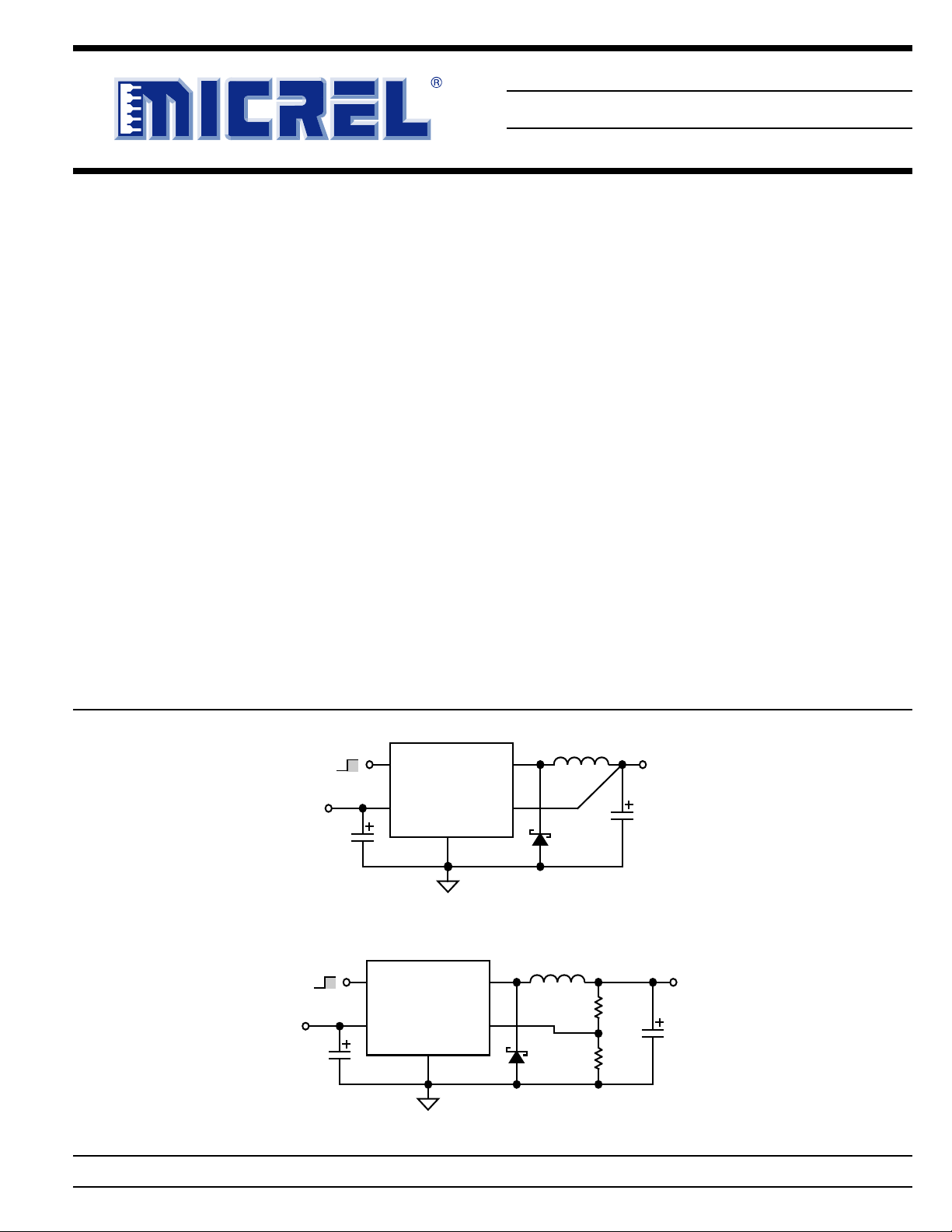
Fixed Regulator
Micrel, Inc. • 2180 Fortune Drive • San Jose, CA 95131 • USA • tel + 1 (408) 944-0800 • fax + 1 (408) 474-1000 • http://www.micrel.com
March 2006 1 MIC4576
Adjustable Regulator
Page 2
MIC4576 Micrel, Inc.
BAT
5 SHDN
4 FB
3 GND
2 SW
1 V
IN
B
A
T
5 SHDN
4 FB
3 GND
2 SW
1 V
IN
Ordering Information
Standard
Part Number
RoHS Compliant
Part Number*
Voltage Temperature Range
Package
MIC4576-3.3BT MIC4576-3.3WT 3.3V –40ºC to +85ºC TO-220-5
MIC4576-5.0BT MIC4576-5.0WT 5.0V –40ºC to +85ºC TO-220-5
MIC4576BT MIC4576WT ADJ. –40ºC to +85ºC TO-220-5
MIC4576-3.3BU MIC4576-3.3WU 3.3V –40ºC to +85ºC TO-263-5
MIC4576-5.0BU MIC4576-5.0WU 5.0V –40ºC to +85ºC TO-263-5
MIC4576BU MIC4576WU ADJ. –40ºC to +85ºC TO-263-5
* RoHS compliant with "high-melting solder" exemption.
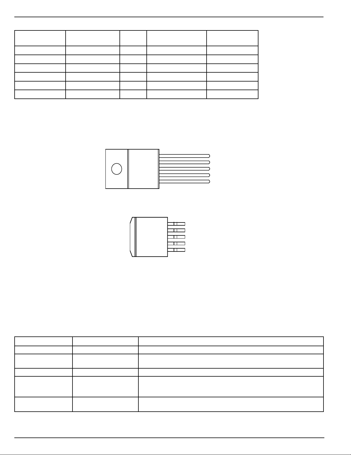
Pin Configuration
5-Pin TO-220 (T)
5-Pin TO-263 (U)
Pin Description
Pin Number Pin Name Pin Function
1 VIN Supply Voltage (Input): Unregulated +4V to +36V supply voltage.
2 SW Switch (Output): Emitter of NPN output switch. Connect to external storage
inductor and Shottky diode.
3, TAB GND Ground
4 FB Feedback (Input): Output voltage feedback to regulator. Connect to output
of supply for fixed versions. Connect to 1.23V tap of resistive divider for
adjustable versions.
5 SHDN Shutdown (Input): Logic low enables regulator. Logic high (> 2.4V) shuts
down regulator.
MIC4576 2 March 2006
Page 3
MIC4576 Micrel, Inc.
Absolute Maximum Ratings
Supply Voltage (VIN) ....................................................+40V
Shutdown Voltage (V
Output Switch (VSW), Steady State ............................... –1V
Feedback Voltage (VFB) [Adjustable] .........................+3.8V
Storage Temperature ................................ –65°C to +150°C
) ............................–0.3V to +36V
SHDN
Operating Ratings
Supply Voltage (VIN) ....................................................+36V
Junction Temperature .............................................. +150°C
Package Thermal Resistance
TO-220, TO-263 (θJA) .........................................65°C/W
TO-220, TO-263 (θJC) ............................................ 2°C/W
Electrical Characteristics
VIN = 12V; I
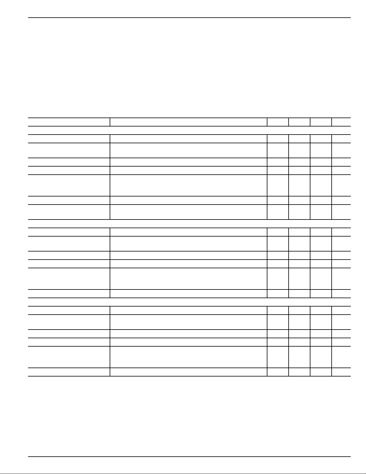
Parameter Condition Min Typ Max Units
MIC4576 [Adjustable]
Feedback Voltage 1.217 1.230 1.243 V
Feedback Voltage 8V ≤ VIN ≤ 36V, 0.5A ≤ I
1.180 1.280 V
Efficiency I
Maximum Duty Cycle (On) VFB = 1.0V 90 95 %
Output Leakage Current VIN = 36V, V
output = 0V 0 2 mA
output = –1V 7.5 35 mA
Quiescent Current VFB = 1.5V 5 10 mA
Feedback Bias Current 50 100 nA
500 nA
MIC4576-3.3
Output Voltage 3.234 3.3 3.366 V
Output Voltage 6V ≤ VIN ≤ 36V, 0.5A ≤ I
3.135 3.465 V
Efficiency I
Maximum Duty Cycle (On) VFB = 2.5V 90 95 %
Output Leakage Current VIN = 36V, V
output = 0V 0 2 mA
output = –1V 7.5 35 mA
Quiescent Current VFB = 4.0V 5 10 mA
MIC4576-5.0
Output Voltage 4.900 5.0 5.100 V
Output Voltage 8V ≤ VIN ≤ 36V, 0.5A ≤ I
4.750 5.250 V
Efficiency I
Maximum Duty Cycle (On) VFB = 4.0V 90 95 %
Output Leakage Current VIN = 36V, V
output = 0V 0 2 mA
output = –1V 7.5 35 mA
Quiescent Current VFB = 6.0V 5 10 mA
= 500mA; TJ = 25°C, bold values indicate –40°C ≤ TJ ≤ +85°C; unless noted.
LOAD
≤ 3A 1.193 1.230 1.267 V
LOAD
= 3A, Note 1 77 %
LOAD
= 1.5V
FB
≤ 3A 3.168 3.3 3.432 V
LOAD
= 3A 72 %
LOAD
= 4.0V
FB
≤ 3A 4.800 5.0 5.200 V
LOAD
= 3A 77 %
LOAD
= 6.0V
FB
March 2006 3 MIC4576
Page 4

MIC4576 Micrel, Inc.
Parameter Condition Min Typ Max Units
MIC4576 / -3.3 / -5.0
Oscillator Frequency 180 200 220 kHz
Saturation Voltage I
2.5 V
Current Limit peak current, tON ≤ 3µs; VFB = 0V 4.2 5.2 7.9 A
3.5 8.5 A
Standby Quiescent Current V
SHDN Input Logic Level V
2.4 V
V
0.8 V
SHDN Input Current V
V
General Note: Devices are ESD protected, however, handling precautions are recommended.
Note 1: V
OUT
= 5V
= 3A 1.7 2.3 V
OUT
= 5V (regulator off), VFB = 0V 50 200 µA
SHDN
= 0V (regulator off) 2.2 1.4 V
OUT
= 3.3V or 5V (regulator on) 1.2 1.0 V
OUT
= 5V (regulator off) 4 30 µA
SHDN
= 0V (regulator on) –10 0.01 10 µA
SHDN
MIC4576 4 March 2006
Page 5

200kHz
Oscillator
1.23V
Bandgap
3A
Switch
Thermal
Shutdown
Current
Limit
Driver
Internal
Regulator
FB
SW
GND
V
IN
+36V max.
C
IN
C
OUT
L1
D1
Shutdown
Enable
SHDN
V
OUT
MIC4576
[Adjustable]
R1
R2
Com-
parator
Error
Amp.
200kHz
Oscillator
1.23V
Bandgap
3A
Switch
Thermal
Shutdown
Current
Limit
Driver
Internal
Regulator
FB
SW
GND
V
IN
+36V max.
C
IN
C
OUT
L1
D1
Shutdown
Enable
SHDN
V
OUT
MIC4576-x.x
R1
R2
Com-
parator
Error
Amp.
Block Diagram with External Components
Adjustable Step-Down Regulator
Block Diagram with External Components
Fixed Step-Down Regulator
MIC4576 Micrel, Inc.
Block Diagrams
March 2006 5 MIC4576
Page 6

MIC4576 Micrel, Inc.
C1
470
µF
35V
D1
1N5822
C2
1000µF
16V
L1
33
µH
GND
FB
SW
MIC4576-3.3BT
SHDN
6V to 24V
3.3V/3A
V
IN
C1 Nichicon UPL1V471MPH, ESR = 0.046Ω
C2 Nichicon UPL1C221MPH, ESR = 0.047Ω
D1 Motorola 1N5822
L1 Coiltronics PL52C-33-1000, DCR = 0.036Ω
L1 Bi HM77-30004, DCR = 0.045Ω, Note 2
Functional Description
The MIC4576 is a variable duty cycle switch-mode regulator
with an internal power switch. Refer to the block diagrams.
Supply Voltage
The MIC4576 operates from a +4V to +36V unregulated
input. Highest efficiency operation is from a supply voltage
around +15V.
Enable/Shutdown
The shutdown (SHDN) input is TTL compatible. Ground the
input if unused. A logic-low enables the regulator. A logichigh shuts down the internal regulator which reduces the
current to typically 50µA.
Feedback
Fixed versions of the regulator have an internal resistive
divider from the feedback (FB) pin. Connect FB directly to
the output line.
Adjustable versions require an external resistive voltage
divider from the output voltage to ground, connected from
the 1.23V tap to FB.
Duty Cycle Control
A fixed-gain error amplifier compares the feedback signal
with a 1.23V bandgap voltage reference. The resulting error
amplifier output voltage is compared to a 200kHz sawtooth
waveform to produce a voltage controlled variable duty cycle
output.
A higher feedback voltage increases the error amplifier output
voltage. A higher error amplifier voltage (comparator inverting
input) causes the comparator to detect only the peaks of the
sawtooth, reducing the duty cycle of the comparator output.
A lower feedback voltage increases the duty cycle.
Output Switching
When the internal switch is on, an increasing current flows
from the supply V
output capacitor C
through external storage inductor L1, to
IN,
and the load. Energy is stored in the
OUT
inductor as the current increases with time.
When the internal switch is turned off, the collapse of the
magnetic field in L1 forces current to flow through fast recovery
diode D1, charging C
OUT
.
Output Capacitor
External output capacitor C
provides stabilization and
OUT
reduces ripple.
Return Paths
During the on portion of the cycle, the output capacitor and
load currents return to the supply ground. During the off
portion of the cycle, current is being supplied to the output
capacitor and load by storage inductor L1, which means that
D1 is part of the high-current return path.
Applications Information
The applications circuits that follow have been constructed
and tested. Refer to Application Note 15 for additional information, including efficiency graphs and manufacturer’s
addresses and telephone numbers for most circuits.
For a mathematical approach to component selection and
circuit design, refer to Application Note 14.
Note 2: Surface-mount component.
MIC4576 6 March 2006
Page 7

MIC4576 Micrel, Inc.
C1
470
µF
35V
D1
1N5822
C2
1000
µF
16V
L1
33
µH
GND
FB
SW
MIC4576-5.0BT
SHDN
8V to 24V
5V/3A
V
IN
C1 Nichicon UPL1J471MPH, ESR = 0.046Ω
C2 Nichicon UPL1C102MPH, ESR = 0.047Ω
D1 Motorola MBR5822
L1 Coiltronics PL52C-33-1000, DCR = 0.036
L1 Bi HM77-30004, DCR = 0.045Ω, Note 2
3
4
25
1
Figure 3. 8V–24V to 5V/3A Buck Converter
Through Hole
C1
470
µF
63V
D1
MBR360
C2
1000µF
16V
L1
33
µH
GND
FB
SW
MIC4576-5.0BT
SHDN
8V to 36V
5V/3A
V
IN
C1 Nichicon UPL1J471MRH, ESR = 0.039Ω
C2 Nichicon UPL1C102MPH, ESR = 0.047Ω
D1 Motorola MBR360
L1 Coiltronics PLS2C-33-1000, DCR = 0.036
L1 Bi HM77-30004, DCR = 0.045Ω, Note 2
3
4
25
1
Figure 4. 8V–36V to 5V/3A Buck Converter
Through Hole
C1
470
µF
63V
MBR360
C2
1000
µF
16V
L1
68
µH
GND
FB
SW
MIC4576BT
SHDN
16V to 36V
12V/3A
V
IN
R2
13.0k
1%
R1
1.50k
1%
C1 Nichicon UPL1J471MPH, ESR = 0.039Ω
C2 Nichicon UPL1C102MPH, ESR = 0.047Ω
D1 Motorola MBR360
L1 Bi HM77-29006, DCR = 0.08Ω
5
1
4
2
3
Figure 5. 16V–36V to 12V/3A Buck Converter
Through Hole
D1
MBR360
C2
1000µF
16V
L1
33µH
GND
FB
SW
MIC4576-5.0BT
SHDN
V
IN
8V to 36V
V
OUT
5V/4A
V
IN
3
4
25
1
C3
470µF
63V
D2
MBR360
L2
33µH
GND
SW
FB
MIC4576-5.0BT
SHDN
V
IN
3
2
4
5
1
4
1
2
3
8
U3
LM358
C5
0.01µF
R3
10K
R1
0.1Ω
C1
470µF
63V
C4
1000µF
16V
R2
0.1Ω
C1, C3 Nichicon UPL1J471MRH, ESR = 0.039Ω
C2, C4 Nichicon UPL1C102MPH, ESR = 0.047Ω
D1, D2 Motorola MBR360
L1, L2 Coiltronics PL52C-33-1000, DCR = 0.036
R1, R2 KRL SP-1-A1-0R100J
U3 National LM358
U1
U2
V
IN
Figure 6. Parallel Switching Regulators
Note 2: Surface-mount component.
March 2006 7 MIC4576
Page 8

MIC4576 Micrel, Inc.
0.018 ±0.008
(0.46 ±0.20)
0.268 REF
(6.81 REF)
0.032 ±0.005
(0.81 ±0.13)
0.550 ±0.010
(13.97 ±0.25)
7°
Typ.
SEATING
PLANE
0.578 ±0.018
(14.68 ±0.46)
0.108 ±0.005
(2.74 ±0.13)
0.050 ±0.005
(1.27 ±0.13)
0.150 D ±0.005
(3.81 D ±0.13)
0.400 ±0.015
(10.16 ±0.38)
0.177 ±0.008
(4.50 ±0.20)
0.103 ±0.013
(2.62±0.33)
0.241 ±0.017
(6.12 ±0.43)
0.067 ±0.005
(1.70 ±0.127)
inch
(mm)
Dimensions:
0.067 ±0.005 0.032 ±0.003
0.360 ±0.005
0.600 ±0.025
0.405 ±0.005
0.060 ±0.005
0.176 ±0.005
8° MAX
0.100 ± 0.01
0.050 ±0.005
0.015 ±0.002
0.004
+0.004
–0.008
SEATING PLANE
0.065 ±0.010
20°± 2°
DIM. = INCH
Package Information
MICREL INC. 2180 FORTUNE DRIVE SAN JOSE, CA 95131 USA
5-Pin TO-220 (T)
TEL + 1 (408) 944-0800 FAX + 1 (408) 474-1000 WEB http://www.micrel.com
5-Pin TO-263 (U)
This information furnished by�
Micrel reserves the right to change circuitry and specifications at any time without notification to the customer.
Micrel Products are not�
reasonably be expected to result in personal injury. Life support devices or systems are devices or systems that (a) are intended for surgical implant into
the body or (b) support or sustain life, and whose failure to perform can be reasonably expected to result in a significant injury to the user. A Purchaser's
use or sale of Micrel Pr�
MIC4576 8 March 2006
Micrel for any damages resulting from such use or sale.
© 2005 Micrel, Inc.
 Loading...