

Page 1
MIC2778 Micrel
V
MIC2778
Voltage Monitor with Adjustable Hysteresis
Preliminary Information
General Description
The MIC2778 is a voltage monitor—uniquely designed to
detect two separate voltage thresholds—combined with a
delay generator and logic. It is designed for monitoring the
battery supply of portable digital systems, particularly PDAs,
pagers, and cellular telephones.
High- and low-voltage thresholds can be adjusted independently, allowing for wide hysteresis. Voltage detection thresholds are accurate to 2%.
If the battery voltage falls below the low-voltage threshold, the
output (RST) is asserted and latched, preventing system
operation until the battery is replaced or recharged. Internal
logic prevents the output from chattering due to battery
recovery or load removal. The output is asserted for 140ms
(minimum) when a fresh battery is inserted. For applications
not requiring built-in delay, see MIC833.
The IC’s power supply input is separate from the detector
inputs, allowing the MIC2778 to be powered from a downstream supply, such a boost converter. Supply current is
extremely low (1µA, typical), making it ideal for portable
applications.
A high-precision 1% grade is available. The MIC2778 is
supplied in Micrel’s IttyBitty™ 5-lead SOT-23-5 package.
Features
• Optimized for PDAs, cellular telephones, pagers,
and other battery-powered devices
• Independently adjustable high- and
low-voltage thresholds
• Internal logic prevents battery-voltage-fluctuation chatter
• High ±2% voltage threshold accuracy; 1% available
• Built in 140ms (minimum) delay deglitches output
• Extremely low 1µA typical supply current
• For applications not requiring built-in delay, see MIC833
• Immune to brief power supply transients
• 5-lead SOT-23 package
Applications
•PDAs
• Pagers
• Cordless phones
• Consumer electronics
• Embedded controllers
• Personal electronics
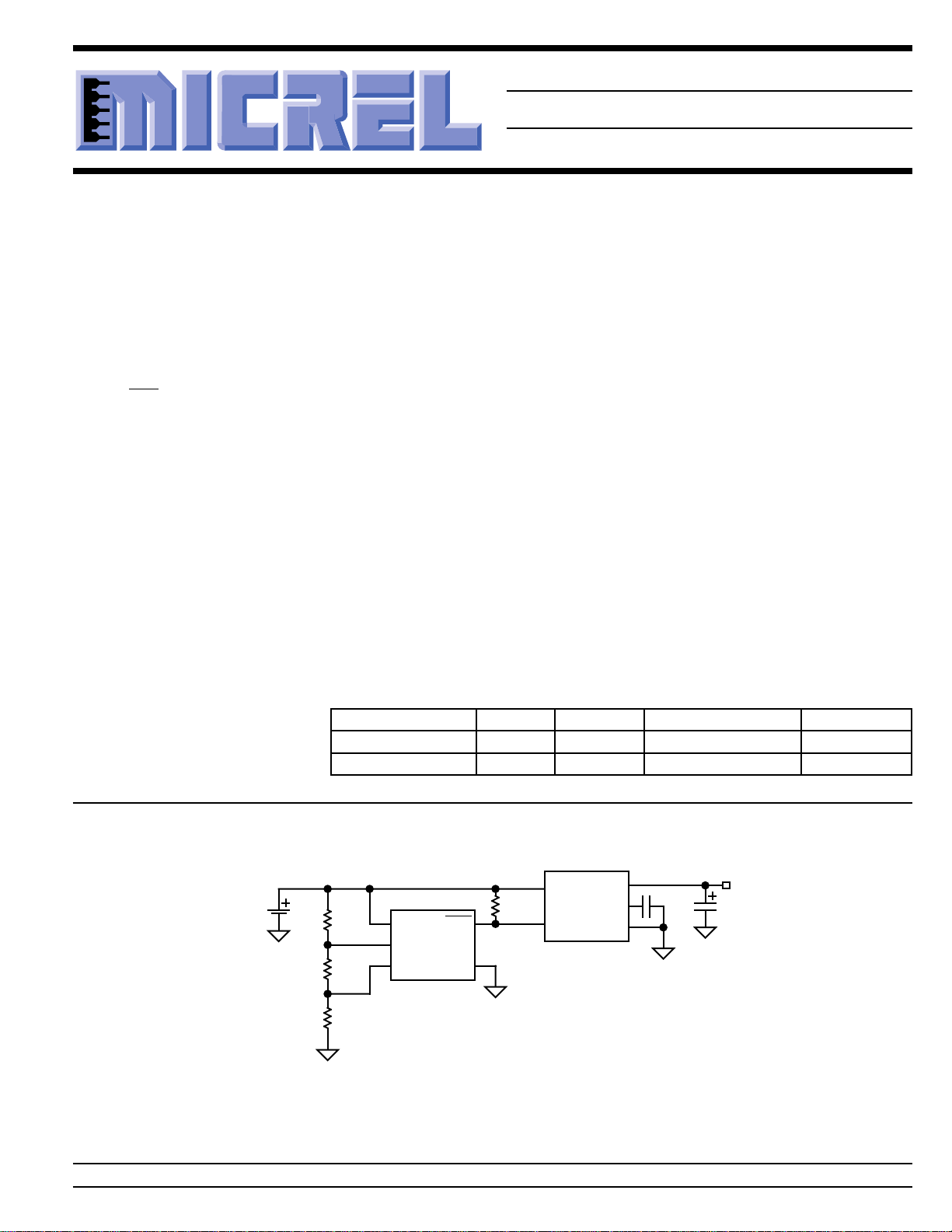
T ypical Application
Li-Ion
Cell
Ordering Information
Part Number Marking Accuracy Temperature Range Package
MIC2778-2BM5 UFB 2% –40°C to +85°C SOT-23-5
MIC2778-1BM5 UFA 1% –40°C to +85°C SOT-23-5
MIC5207-3.0BM5
IN
EN
604k
1%
56k
1%
340k
1%
MIC2778
LTH
HTH
V
BAT(hi)
V
BAT(lo)
RSTVDD
GND
= 3.6V
= 3.1V
100k
Cellular Telephone Battery Monitor
OUT
BYP
GND
470pF
OUT
3.0V
4.7µF
IttyBitty™ is a trademark of Micrel, Inc.
Micrel, Inc. • 1849 Fortune Drive • San Jose, CA 95131 • USA • tel + 1 (408) 944-0800 • fax + 1 (408) 944-0970 • http://www.micrel.com
October 1999 1 MIC2778
Page 2

MIC2778 Micrel
Pin Configuration
GND
2
HTH
13
VDDRST
LTH
45
SOT-23-5 (M5)
Pin Description
Pin Number Pin Name Pin Function
1 HTH High-Voltage Theshold (Input): Analog input to a comparator. When the
2 GND Ground
3 LTH Low-Voltage Threshold (Input): Analog input to a comparator. This is the
4 RST Reset (Output): Active-low, open-drain output. This output is asserted and
5 VDD Power Supply (Input): Independent supply input for internal circuitry.
level on this pin initially rises above V
, the delay generator cycles and the
REF
RST remains low for a minimum of 140ms.
voltage monitor input assigned to detect a low voltage condition. When the
level on this pin falls below V
latched until V
latched when V
remains latched until V
HTH
LTH
> V
<V
REF
REF
HTH
, RST is asserted and the condition is
REF
.
, indicating a low voltage condition. This state
> V
REF
.
MIC2778 2 October 1999
Page 3
MIC2778 Micrel
V
HTH
V
BATT
V
LTH
0V
V
RSTH
V
RSTL
t
RST
t
RST
A
A
V
RST
Absolute Maximum Ratings (Note 1)
Supply Voltage (VDD) ..................................... –0.3V to +7V
Input Voltages (VHI, VLO) ............................... –0.3V to +7V
RST Output Current (I
Storage Temperature (TS) .......................–65°C to +150°C
) .........................................20mA
RST
Operating Ratings (Note 2)
Supply Voltage (VDD) .................................. +1.5V to +5.5V
Input Voltages (V
Ambient Temperature Range (TA) ............. –40°C to +85°C
Package Thermal Resistance ...............................256°C/W
RST
, V
LTH
, V
) ............. –0.3V to +6.0V
HTH
ESD Rating, Note 3 ......................................................2kV
Electrical Characteristics
1.5V ≤ VDD ≤ 5.5V; TA = +25°C, bold values indicate –40°C ≤ TA ≤ +85°C; unless noted
Symbol Parameter Condition Min Typ Max Units
I
DD
I
LTH, IHTH
V
REF
t
D
t
RESET
V
RST
Note 1. Exceeding the absolute maximum rating may damage the device.
Note 2. The device is not guaranteed to function outside its operating rating.
Note 3. Devices are ESD sensitive. Handling precautions recommended. Human body model, 1.5k in series with 100pF.
Note 4. VDD operating range is 1.5V to 5.5V. Output is guaranteed to be held low down to VDD = 1.2V.
Supply Current RST not asserted 1 2 µA
Input Leakage Current 5pA
10 nA
Reference Voltage 1.240 V
MIC2778-2 1.215 1.265 V
MIC2778-1 1.228 1.252 V
Propagation Delay V
LTH
V
REF(min)
= V
REF(max)
– 100mV
+100mV to 5 µs
Reset Pulse Width 140 420 ms
Voltage-Low Reset RST asserted, I
RST asserted, I
= 1.6mA, VDD ≥ 1.6V 0.3 V
SINK
= 100µA, VDD ≥ 1.2V, 0.4 V
SINK
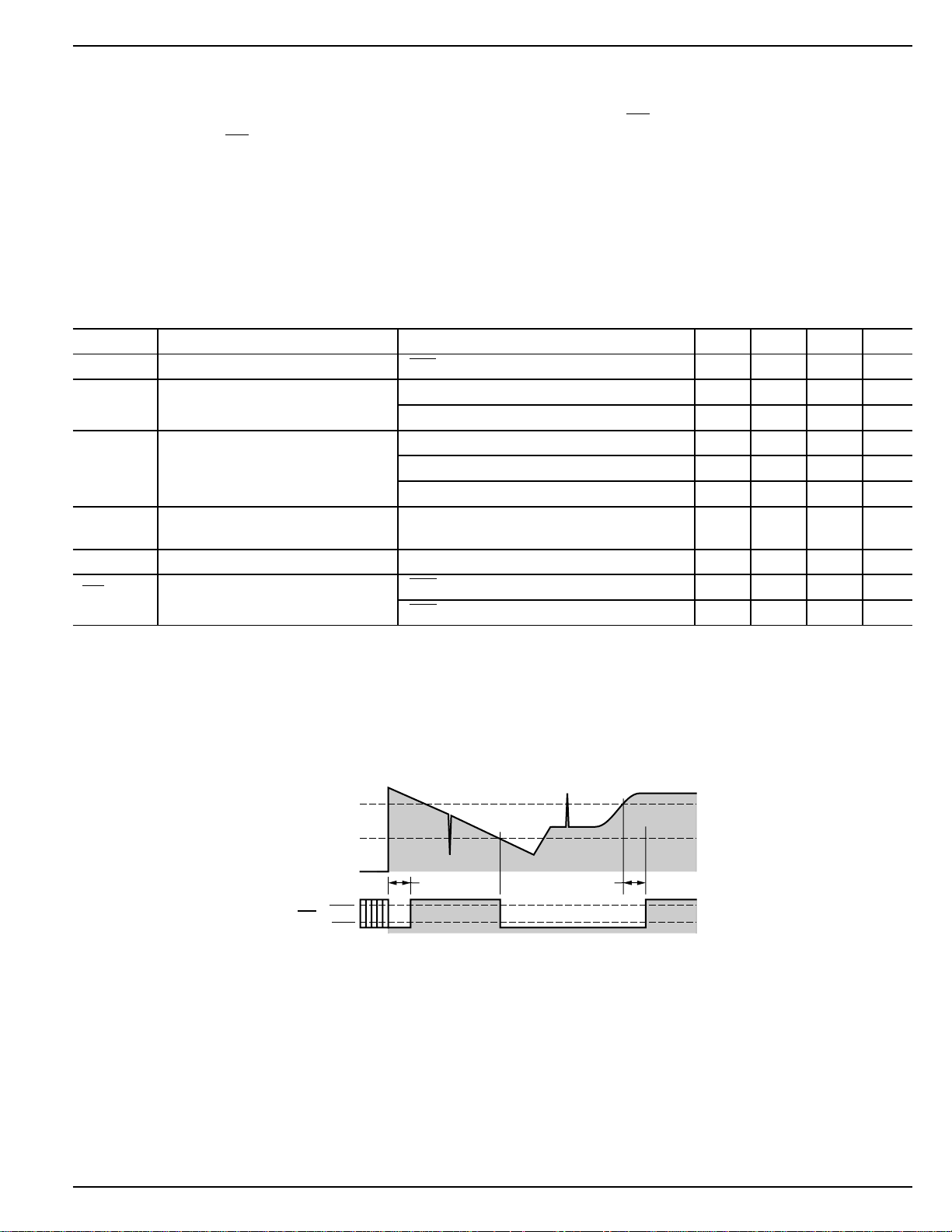
Timing Diagram
Propagation delays not shown for clarity.
Note A. The MIC2778 ignores very brief transients.
October 1999 3 MIC2778
See “Applications Information” for details.
Page 4
MIC2778 Micrel
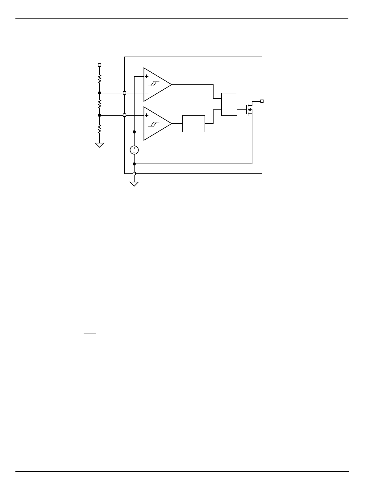
Functional Diagram
V
BATT
Low-Voltage
Detect
V
LO
V
HI
LTH
HTH
High-Voltage
1.24V
Bandgap
Reference
GND
Detect
Delay
Line
RSQ
RST
Q
MIC2778
Functional Description
The MIC2778 monitors the voltage of a battery and detects
when it is discharged below a programmed level. Upon being
replaced, or being recharged above a second higher programmed trip point, the output remains low for a minimum of
140ms and then sends a reset signal to a microprocessor or
other downstream component.
Voltage Low Output
The voltage-low output (RST) is an active-low, open-drain
output which sinks current when the MIC2778 detects a low
input voltage.
Trip Points
Battery voltage is monitored by a comparator via a voltage
divider network. The divided voltage is compared to an
internal reference voltage. When the voltage at the LTH input
pin drops below the internal reference voltage, the output
pulls low. At this point, the voltage at HTH is assumed to be
below the reference voltage.
Delay
At power-on or when the battery is replaced or recharged,
and the voltage at HTH exceeds the reference voltage, the
output goes high after a minimum delay of 140ms.
MIC2778 4 October 1999
Page 5
MIC2778 Micrel
R1 1M R2 R3=−−Ω
Applications Information
Output
Since the MIC2778 output is an open-drain MOSFET, most
applications will require a pull-up resistor. The value of the
resistor should not be too large or leakage effects may
dominate. 470kΩ is the maximum recommended value.
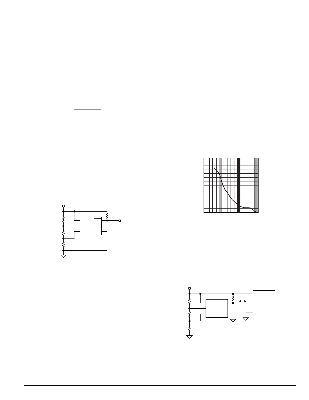
Programming the Thresholds
The low-voltage threshold is calculated using:
R1 R2 R3
++
VV
BAT(lo) REF
=
R2 R3
+
The high-voltage threshold is calculated using:
R1 R2 R3
++
VV
BAT(hi) REF
=
R3
where, for both equations:
V 1.240V
=
REF
In order to provide the additional criteria needed to solve for
the resistor values, the resistors can be selected such that
they have a given total value, that is, R1 + R2 + R3 = R
A value such as 1MΩ for R
because it draws minimum battery current but has no significant effect on accuracy.
When working with large resistors, a small amount of leakage
current can cause voltage offsets that degrade system accuracy. The maximum recommended total resistance from
V
to ground is 3MΩ.
BAT
R1
R2
R3
V
BATT
604k
1%
56k
1%
340k
1%
MIC2778
LTH
HTH
Figure 1. Example Circuit
Once the desired trip points are determined, set the V
threshold first.
For example, use a total of 1MΩ = R1 + R2 + R3. For a typical
single-cell lithium ion battery, 3.6V is a good “high threshold”
because at 3.6V the battery is moderately charged. Solving
for R3:
1M
Ω
V 1.24
BAT(hi)
=
R3
R3 344k=Ω
Once R3 is determined, the equation for V
to determine R2. A single lithium-ion cell should not be
discharged below 2.5V. Many applications limit the drain to
is a reasonable value
TOTAL
470k
RSTVDD
GND
BAT(lo)
TOTAL
BAT(hi)
can be used
3.1V. Using 3.1V for the V
threshold allows calculation
BAT(lo)
of the two remaining resistor values.
1M
Ω
V 3.1V 1.24
BAT(lo)
==
R2 344k
+
R2 56k=Ω
R1 600k=Ω
The accuracy of the resistors can be chosen based upon the
accuracy required by the system.
Input Transients
The MIC2778 is inherently immune to very short negativegoing “glitches.” Very brief transients may exceed the V
threshold without tripping the output.
As shown in Figure 2, the narrower the transient, the deeper
the threshold overdrive that will be ignored by the MIC2778.
The graph represents the typical allowable transient duration
for a given amount of threshold overdrive that will not generate a reset.
.
140
120
100
80
60
40
20
MAX. TRANSIENT DURATION (µs)
RESET COMP. OVERDRIVE, V
Input Transient
Response
0
1 10 100 1000
REF–VLTH
(mV)
Figure 2. Input Transient Response
Interfacing to Processors
With Bidirectional Reset Pins
Some microprocessors have reset signal pins that are bidirectional, rather than input only. The Motorola 68HC11 family
is one example. Because the MIC2778’s output is open drain,
it can be connected directly to the processor’s reset pin using
only the pull-up resistor normally required. See Figure 4.
V
R1
R2
R3
BATT
604k
1%
56k
1%
340k
1%
MIC2778
LTH
HTH
100k
RSTVDD
GND
Microprocessor
Supply In
Reset In
GND
Figure 4. Interfacing to Bidirectional Reset Pin
BAT(lo)
October 1999 5 MIC2778
Page 6
MIC2778 Micrel
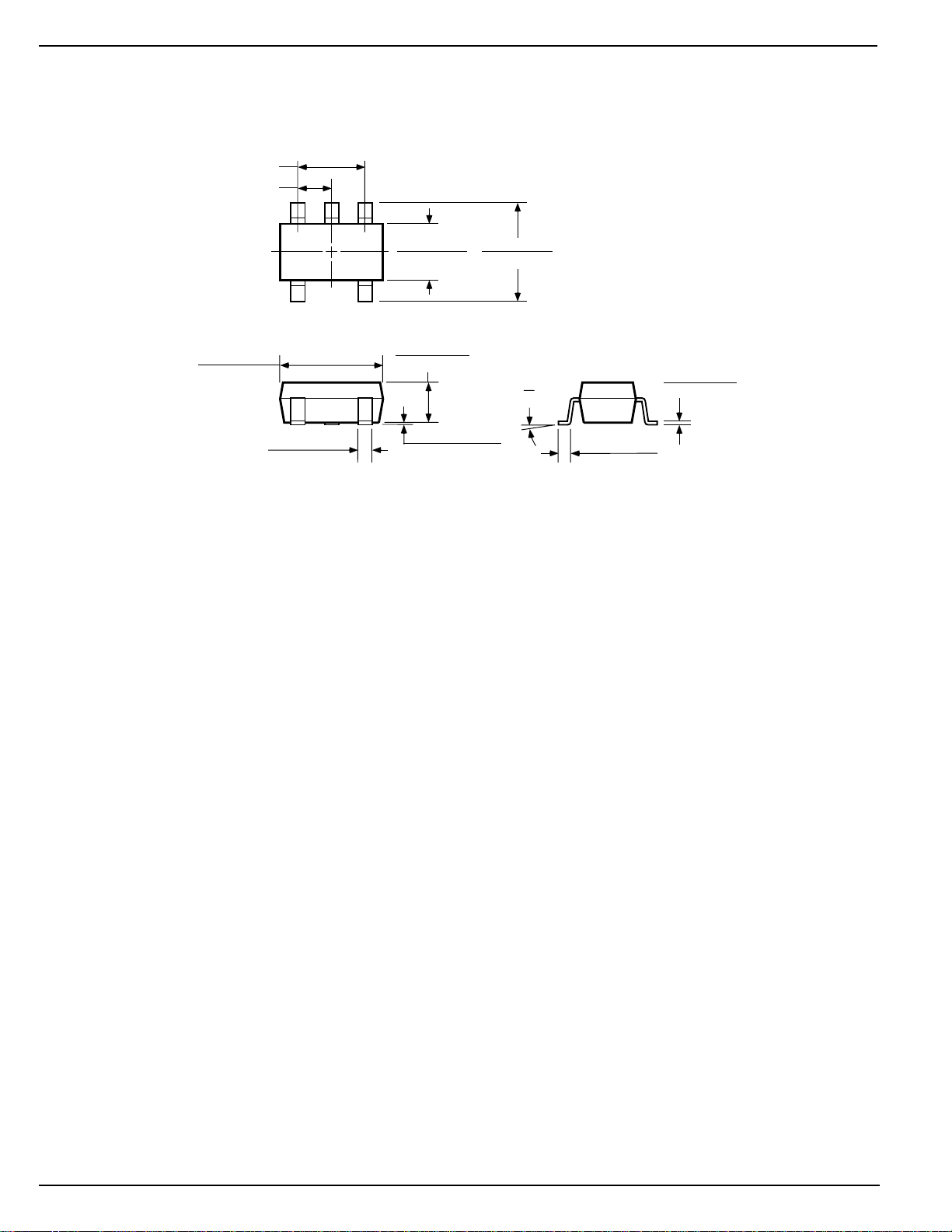
Package Information
1.90 (0.075) REF
0.95 (0.037) REF
3.02 (0.119)
2.80 (0.110)
0.50 (0.020)
0.35 (0.014)
1.75 (0.069)
1.50 (0.059)
1.30 (0.051)
0.90 (0.035)
0.15 (0.006)
0.00 (0.000)
SOT-23-5 (M5)
3.00 (0.118)
2.60 (0.102)
10°
0°
DIMENSIONS:
MM (INCH)
0.20 (0.008)
0.09 (0.004)
0.60 (0.024)
0.10 (0.004)
MIC2778 6 October 1999
Page 7

MIC2778 Micrel
October 1999 7 MIC2778
Page 8

MIC2778 Micrel
MICREL INC. 1849 FORTUNE DRIVE SAN JOSE, CA 95131 USA
TEL + 1 (408) 944-0800 FAX + 1 (408) 944-0970 WEB http://www.micrel.com
This information is believed to be accurate and reliable, however no responsibility is assumed by Micrel for its use nor for any infringement of patents or
other rights of third parties resulting from its use. No license is granted by implication or otherwise under any patent or patent right of Micrel Inc.
© 1999 Micrel Incorporated
MIC2778 8 October 1999
 Loading...