

Page 1

查询MIC2003-0.5YM5供应商
General Description
MIC2003/2013
Current Limiting Circuit Protector
Features
MIC2003 and MIC2013 are high-side current limiting
devices, designed for power distribution applications in
PCs, PDAs, printers and peripheral devices.
MIC2003 and MIC2013 are thermally protected and will
shutdown should their internal temperature reach unsafe
levels, protecting both the device and the load, under
high current or fault conditions. Both devices are fully
self-contained, with the current limit value being factory
set to one of several convenient levels.
MIC2013 offers a unique new feature: Kickstart
which allows momentary high current surges to pass
unrestricted without sacrificing overall system safety.
MIC2003 and MIC2013 are excellent choices for USB
and IEEE 1394 (FireWire) applications or for any system
where current limiting and power control are desired.
The MIC2003 and MIC2013 are offered in space saving
6 pin SOT-23 and 2mm x 2mm MLF packages.
Data sheets and support documentation can be found
on Micrel’s web site at www.micrel.com.
_________________________________________________________________________________________________________
™
• 70mΩ typical on-resistance
• 2.5V - 5.5V operating range
• Pre-set current limit values of 0.5A, 0.8A and 1.2A
™
• Kickstart
• Thermal Protection
• Under voltage lock-out
• Low quiescent current
,
Applications
• USB / IEEE 1394 Power Distribution
• Desktop and Laptop PCs
• Set top boxes
• Game consoles
• PDAs
• Printers
• Docking stations
• Chargers
Typical Application
Kickstart is a trademark of Micrel, Inc
MLF and MicroLeadFrame are trademarks of Amkor Technology, Inc.
Micrel Inc. • 2180 Fortune Drive • San Jose, CA 95131 • USA • tel +1 (408) 944-0800 • fax + 1 (408) 474-1000 • http://www.micrel.com
October 2005
Figure 1. Typical Application Circuit
M9999-xxxx04
(408) 955-1690
Page 2

Micrel MIC2003/MIC20013
MIC2000 Family Members
Part Number
Normal Limiting Kickstart I Limit I Adj. Enable C
Pin Function
SLEW
FAULT/ DLM*
Discharge
2003 2013 -- -- -- -- -- --
2004 2014 -- ▲ -- -- -- ▲
2005 2015 -- ▲ ▲ ▲ -- --
2006 2016
Fixed
-- ▲ ▲ -- ▲ --
2007 2017 ▲ ▲ ▲ -- -- ▲
2008 2018 ▲ ▲ ▲ -- -- --
2009 2019
Adj.
▲ ▲ -- ▲ -- --
* Dynamic Load Management Adj = Adjustable current limit Fixed = Factory programmed current limit
Ordering Information
FD05
FD08
FD12
D05
D08
D12
FL05
FL08
FL12
L05
L09
L12
(1)
Current Limit Kickstart Pb-Free Package
Yes
SOT-23-5
2mmX2mm MLF
0.5A
0.8A
1.2A
0.5A
0.8A
No
1.2A
0.5A
0.8A
1.2A
0.5A
0.8A
Yes
SOT-23-5
2mmX2mm MLF
1.2A
Part Number Marking
MIC2003-0.5YM5
MIC2003-0.8YM5
MIC2003-1.2YM5
MIC2003-0.5YML
MIC2003-0.8YML
MIC2003-1.2YML
MIC2013-0.5YM5
MIC2013-0.8YM5
MIC2013-1.2YM5
MIC2013-0.5YML
MIC2013-0.8YML
MIC2013-1.2YML
Note:
1. Under-bar symbol ( _ ) may not be to scale
Load
October 2005
2
M9999-102605
or (408) 955-1690
Page 3

Micrel MIC2003/MIC20013
Pin Configuration
GND
V
NIC
OUT
V
1
NODAP
2
6
IN
5
GND
EDISKCAB
DNUORGSI
NIC
3
V
IN
1
2
NIC
34
6-Lead 2mmX2mm MLF (ML)
Top View
NIC
Pin Description
Pin
Number
SOT-23
1 6 VIN Input
2 5 GND -- Ground.
3 4 NIC --
4 3 NIC --
2 NIC --
5 1 VOUT Output
Pin
Number
MLF
Pin
Name
Type Description
Supply input. This pin provides power to both the output switch and the
MIC2003/2013’s internal control circuitry.
No internal connection. An electrical signal to this pin will have no effect on
device operation.
No internal connection. An electrical signal to this pin will have no effect on
device operation.
No internal connection. An electrical signal to this pin will have no effect on
device operation.
Switch output. The load being driven by MIC2003/2013 is connected to this
pin.
4
NIC V
SOT 23-5 (M5)
Top View
5
OUT
October 2005
3
M9999-102605
or (408) 955-1690
Page 4
Micrel MIC2003/MIC20013
Absolute Maximum Ratings
VIN, V
............................................................ –0.3 to 6V
OUT
(1)
All other pins.................................................. –0.3 to 5.5V
Power Dissipation.................................. Internally Limited
Continuous Output Current..................................... 2.25A
Maximum Junction Temperature........................... 150°C
Storage Temperature .............................. –65°C to 150°C
Operating Ratings
Supply Voltage............................................. 2.5V to 5.5V
Continuous Output Current Range .................... 0 to 2.1A
Ambient Temperature Range ....................–40°C to 85°C
Package Thermal Resistance (θ
SOT-23-5 ............................................. 230°C/W
MLF 2x2 mm
(5)
(2)
)
JA
......................................... 90°C/W
Electrical Characteristics
VIN = 5V, T
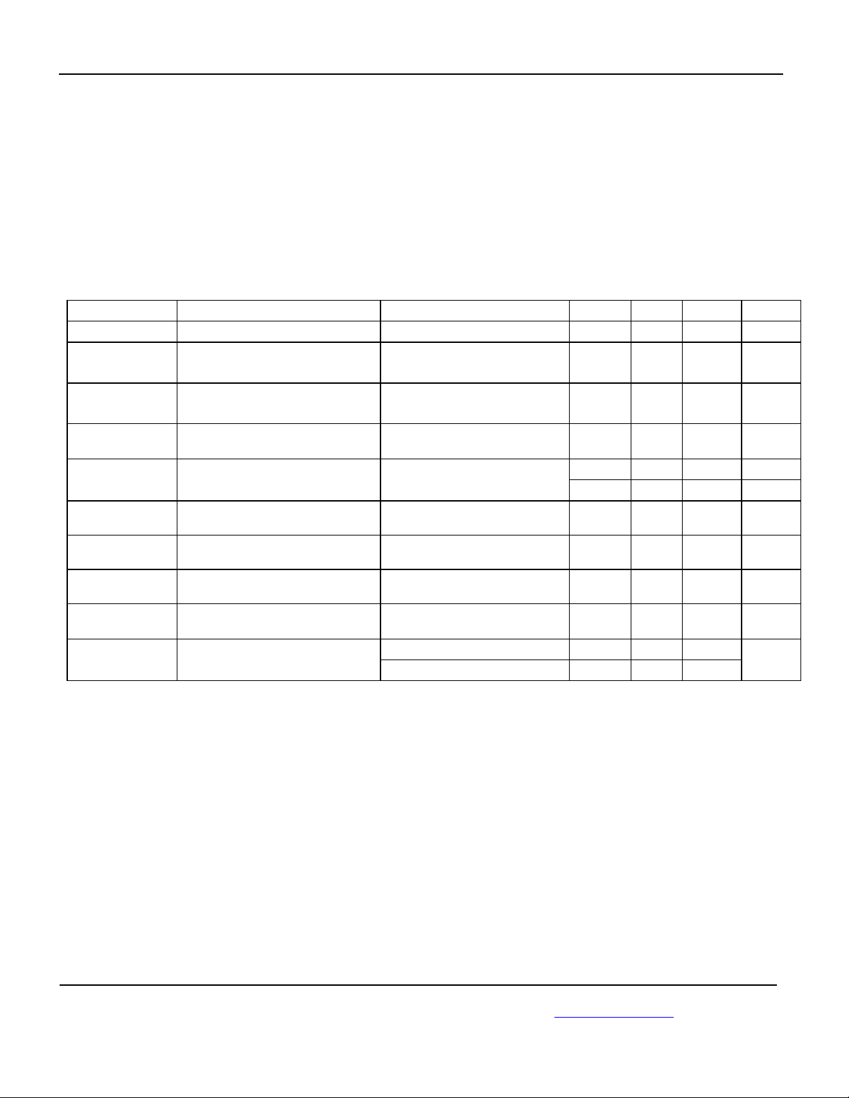
Symbol Parameter Conditions Min Typ Max Units
V
IN
I
IN
I
IN
I
LEAK
DS(ON)
I
LIMIT
= 25°C unless specified otherwise. Bold indicates –40°C to +85°C limits.
AMBIENT
Switch Input Voltage
Internal Supply Current Switch = OFF,
ENABLE = 0V
Internal Supply Current Switch = ON, I
OUT
= 0
ENABLE = 1.5V
Output Leakage Current
= 5V, V
IN
= 0 V, ENABLE
OUT
V
= 0
Power Switch Resistance VIN = 5V, I
Current Limit: –0.5 V
= 0.8VIN to V
OUT
= 100 mA
OUT
= 1V 0.5 0.7 0.9 A
OUT
2.5
1
80
12
70 100 mΩ R
5.5
5
300
100
125
V
µA
µA
µA
mΩ
I
LIMIT
I
LIMIT
I
LIMIT_2nd
THRESHOLD
Current Limit: –0.8 V
Current Limit: –1.2 V
Secondary current limit
(Kickstart)
Over-temperature Threshold
= 0.8VIN to V
OUT
= 0.8VIN, to V
OUT
MIC2013, V
= 2.7V 2.2 4 6 A
IN
= 1V 0.8 1.1 1.5 A
OUT
= 1V 1.2 1.6 2.1 A
OUT
TJ increasing 145 OT
T
decreasing 135
J
°C
October 2005
4
M9999-102605
or (408) 955-1690
Page 5

Micrel MIC2003/MIC20013
AC Characteristics
Symbol Parameter Condition Min Typ Max Units
t
LIMIT
t
RESET
Delay before current limiting Secondary current limit
(MIC2013)
Delay before resetting
Kickstart current limit delay,
t
LIMIT
Out of current limit following a
current limit.
(MIC2013)
77
77
128
128
192
192
ms
ms
ESD
Symbol Parameter Condition Min Typ Max Units
ESD_HB
V
ESD_MCHN
Electro Static Discharge
Voltage: Human Body Model
Electro Static Discharge
Voltage; Machine Model
Notes:
1. Exceeding the absolute maximum rating may damage the device.
2. The device is not guaranteed to function outside its operating rating.
3. Devices are ESD sensitive. Handling precautions recommended. Human body model, 1.5k in series with 100pF.
4. Specification for packaged product only.
5. Requires proper thermal mounting to achieve this performance.
V
and GND ± 4 kV V
OUT
All other pins
All pins
Machine Model
± 2
± 200 V
kV
October 2005
5
M9999-102605
or (408) 955-1690
Page 6

Micrel MIC2003/MIC20013
Timing Diagrams
ENABLE
50%
t
ON_DLY
90%
50%
t
OFF_DLY
VOUT
10%
Switching Delay Times
t
RISE
t
RISE
90%
10%
Rise and Fall Times
90%
90%
10%
t
FAL L
October 2005
10%
Output Rise Time
6
VOUT
M9999-102605
or (408) 955-1690
Page 7

Micrel MIC2003/MIC20013
Typical Characteristics
Supply Current
100
SUPPLY CURRENT (µA)
Output Enabled
25°C
80
60
40
20
0
23456
-40°C
VIN (V)
UVSD Threshold
248.0
247.5
247.0
246.5
246.0
THRESHOLD (mV)
245.5
245.0
1.40
1.20
1.00
0.80
(A)
0.60
LIMIT
I
0.40
0.20
0.00
vs. Temperature
-50 -30 -10 10 30 50 70 90
TEMPERATURE (°C)
I
vs. Temperature
LIMIT
(MIC20xx - 0.8)
Note:
5V
Please note that the 3
3V
plots overlay each
2.5V
-50-30-101030507090
TEMPERATURE (°C)
RON vs.
120
100
80
60
(mOhm)
ON
40
R
20
0
-50-30-101030507090
Temperature
3.3V
TEMPERATURE (°C)
2.5V
85°C
5V
Supply Current
1.00
0.90
0.80
0.70
0.60
0.50
0.40
0.30
0.20
SUPPLY CURRENT (µA)
0.10
1.65
1.60
1.55
1.50
(A)
1.45
LIMIT
I
1.40
1.35
1.30
1.25
0.75
0.73
0.71
0.69
0.67
(A)
0.65
LIMIT
0.63
I
0.61
0.59
0.57
0.55
Output Disabled
-40°C
85°C
0
234567
-50-30-101030507090
VIN (V)
I
vs. Temperature
LIMIT
(MIC20xx-1.2)
VIN = 2.5V
VIN = 3V
VIN = 5V
TEMPERATURE (°C)
I
vs. Temperature
LIMIT
25°C
(MIC20xx - 0.5)
5V
3V
2.5V
-50-30-101030507090
TEMPERATURE (°C)
Switch Leakage Current - OFF
1.00
0.90
0.80
0.70
0.60
0.50
(µA)
0.40
0.30
0.20
0.10
0
-50 -30 -10 10 30 50 70 90
TEMPERATURE (°C)
I
vs.
LIMIT
1.4
1.2
1.0
0.8
(A)
0.6
LIMIT
I
0.4
0.2
-50 -30 -10 10 30 50 70 90
Temperature
0
TEMPERATURE (°C)
RON vs.
100
(mOhm)
ON
R
Supply Voltage
80
60
40
20
0
22.533.544.555.5
VIN (V)
0.8A
0.5A
1.2A
October 2005
7
M9999-102605
or (408) 955-1690
Page 8
Micrel MIC2003/MIC20013
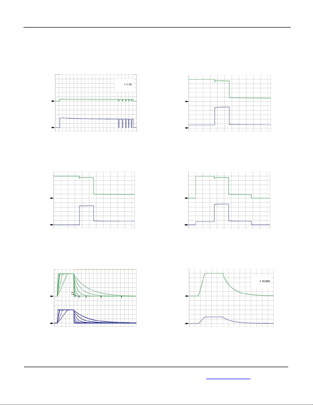
Functional Characteristics
V
(1V/div)
I
(250mA/div)
V
OUT
(1V/div)
Current Limit Response Thermal Shutdown
VIN = 5.0V
R
LOAD
C
= 47µF
LOAD
OUT
OUT
0
50 100 150
200 250
300 350 400 450 500 550
Time (ms)
V
(1V/div)
I
(0.5A/div)
OUT
OUT
Kickstart Response
No Load to Short Circuit
V
OUT
(1V/div)
Normal Load with Temporary High Load
0
50 100 150
Normal Load with Temporary Short Circuit
Kickstart Response
200 250
300 350 400 450 500 550
Time (ms)
Kickstart Response
I
OUT
(0.5A/div)
V
OUT
(1V/div)
I
OUT
(200mA/div)
October 2005
0
50 100 150
10µF
0
4812
200 250
Time (ms)
Inrush Current Response
MIC20xx-0.5
0µF
22µF
100µF
47µF
16 20
Time (ms)
300 350 400 450 500 550
220µF
24 28 32 36 40
470µF
I
OUT
(0.5A/div)
0
50 100 150
200 250
300 350 400 450 500 550
Time (ms)
Turn-On/Turn-Off
= 5.0V
V
IN
R
LOAD
C
= 100nF
LOAD
V
OUT
(1V/div)
I
OUT
(200mA/div)
0
246
Time (ms)
810
12 14
8
M9999-102605
or (408) 955-1690
Page 9

Micrel MIC2003/MIC20013
V
(1V/div)
(1/div)
V
(1V/div)
OUT
V
IN
OUT
0
4 8 12 16
UVLO Decreasing
20 24 28 32 36 40 44
Time (µs)
UVSD
UVLO Increasing
V
OUT
(1V/div)
V
IN
(1/div)
48
0
4 8 12 16
20 24 28 32 36 40 44
Time (µs)
48
V
IN
(1/div)
0
20 40
60
100 120 140 160 180
80
Time (µs)
200
October 2005
9
M9999-102605
or (408) 955-1690
Page 10

Micrel MIC2003/MIC20013
Functional Diagram
rednU
egatloV
rotceteD
tnerruC
TEFrorriM
rewoP
TEF
VIN
cigoLlortnoC
remiTyaleDdna
lamrehT
rosneS
V
etaRwelS
lortnoC
FER
yrotcaF
detsujda
lortnoCetaG
timiLtnerruC
pooLlortnoc
Figure 2 MIC2003/2013 Block Diagram
VOUT
GND
October 2005
10
M9999-102605
or (408) 955-1690
Page 11

Micrel MIC2003/MIC20013
Functional Description
Input and Output
V
is both the power supply connection for the internal
IN
circuitry driving the switch and the input (Source
connection) of the power MOSFET switch. V
OUT
is the
Drain connection of the power MOSFET and supplies
power to the load. In a typical circuit, current flows from
to V
V
IN
directional when enabled, if V
current will flow from V
toward the load. Since the switch is bi-
OUT
is greater than VIN,
OUT
to VIN.
OUT
When the switch is disabled, current will not flow to the
load, except for a small unavoidable leakage current of
a few microamps. However, should V
exceed VIN by
OUT
more than a diode drop (~0.6V), while the switch is
disabled, current will flow from output to input via the
power MOSFET’s body diode. This effect can be used
to advantage when large bypass capacitors are placed
on MIC2003/2013’s’s output. When power to the switch
is removed, the output capacitor will be automatically
discharged.
If discharging C
is required by your application,
LOAD
consider using MIC2003/2013 or MIC2007/2017 in place
of MIC2003/2013. These MIC2000 family members are
equipped with a discharge FET to insure complete
discharge of C
LOAD
.
Current Sensing and Limiting
MIC2003/2013 protects the system power supply and
load from damage by continuously monitoring current
through the on-chip power MOSFET. Load current is
monitored by means of a current mirror in parallel with
the power MOSFET switch. Current limiting is invoked
when the load exceeds an internally set over-current
threshold. When current limiting is activated the output
current is constrained to the limit value, and remains at
this level until either the load/fault is removed, the load’s
current requirement drops below the limiting value, or
the MIC2003/2013 goes into thermal shutdown.
Kickstart (MIC2013 only)
The MIC2013 is designed to allow momentary current
surges (Kickstart) before the onset of current limiting,
which permits dynamic loads, such as small disk drives
or portable printers to draw the energy needed to
overcome inertial loads without sacrificing system
safety. In this respect, the MIC2013 differs markedly
from MIC2003 and its peers, which immediately limit
load current, potentially starving the motor and causing
the appliance to stall or stutter.
During this delay period, typically 128 ms, a secondary
current limit is in effect. If the load demands a current in
excess the secondary limit, MIC2013 acts immediately
to restrict output current to the secondary limit for the
October 2005
duration of the Kickstart period. After this time the
MIC2013 reverts to its normal current limit. An example
of Kickstart operation is shown below.
TUO
TUO
Figure 3. Kickstart Operation
Picture Key:
A) MIC2013 is enabled into an excessive load (slew
rate limiting not visible at this time scale) The initial
current surge is limited by either the overall circuit
resistance and power supply compliance, or the
secondary current limit, whichever is less.
B) R
C) Kickstart period.
D) Current limiting initiated. FAULT/ goes LOW.
E) V
F) Thermal shutdown followed by thermal cycling.
G) Excessive load released, normal load remains.
H) FAULT/ delay period followed by FAULT/ going
Slew Rate Control
Large capacitive loads can create significant current
surges when charged through a high-side switch such
as the MIC2003/2013. For this reason, MIC2003/2013
provides built-in slew rate control to limit the initial inrush
currents upon enabling the power MOSFET switch.
Slew rate control is active upon powering up, and upon
re-enabling the load. At shutdown, the discharge slew
rate is controlled by the external load and output
capacitor.
11
of the power FET increases due to internal
ON
heating (effect exaggerated for emphasis).
is non-zero (load is heavy, but not a dead short
OUT
where V
= 0. Limiting response will be the same
OUT
for dead shorts).
MIC2013 drops out of current limiting.
HIGH.
M9999-102605
or (408) 955-1690
Page 12

Micrel MIC2003/MIC20013
Thermal Shutdown
Thermal shutdown is employed to protect
MIC2003/2013 from damage should the die temperature
exceed safe operating levels. Thermal shutdown shuts
off the output MOSFET and asserts the FAULT/ output if
the die temperature reaches 145°C.
MIC2003/2013 will automatically resume operation
when the die temperature cools down to 135°C. If
resumed operation results in reheating of the die,
another shutdown cycle will occur and the
MIC2003/2013 will continue cycling between ON and
OFF states until the offending load has been removed.
Depending on PCB layout, package type, ambient
temperature, etc., hundreds of milliseconds may elapse
from the incidence of a fault to the output MOSFET
being shut off. This delay is due to thermal time
constants within the system itself. In no event will the
device be damaged due to thermal overload because
die temperature is monitored continuously by on-chip
circuitry.
October 2005
12
M9999-102605
or (408) 955-1690
Page 13

Micrel MIC2003/MIC20013
Application Information
I
vs. I
LIMIT
MIC2003/2013’s’s current limiting circuitry is designed to
act as a constant current source to the load. As the load
tries to pull more than the allotted current, V
and the input to output voltage differential increases.
When V
reduce the drain of fault current on the system’s power
supply and to limit internal heating of MIC2003/2013.
When measuring I
dependence in mind, otherwise the measurement data
may appear to indicate a problem when none really
exists. This voltage dependence is illustrated in Figures
4 and 5.
In Figure 4 output current is measured as V
below V
below V
remains constant throughout the remainder of the test.
In Figure 5 this test is repeated but with V
exceeding 1V.
When V
circuitry responds by decreasing I
Figure 5. In this demonstration, V
and I
applications V
Ohm’s law by the load and the limiting current.
measured
OUT
drops
OUT
IN -VOUT
IN
IN
IN
OUT
exceeds 1V, I
it is important to bear this voltage
OUT
, with the test terminating when V
. Observe that once I
- V
> 1V, MIC2003/2013’s current limiting
OUT
is the measured quantity. In real life
is determined in accordance with
OUT
drops below I
OUT
OUT
is reached I
LIMIT
, as can be seen in
OUT
is being controlled
OUT
LIMIT
is pulled
is 1V
OUT
- V
IN
to
OUT
OUT
Figure 5. I
This folding back of I
as a function of V
I
LIMIT
of V
between I
OUT
1) is determined by R
in Current Limiting for V
OUT
can be generalized by plotting
LIMIT
, as shown below. The slope
OUT
= 0 and I
OUT
of MIC2003/2013 and I
ON
OUT
= I
Normalized Output Current
vs. Output Voltage (5V)
1.2
LIMIT
OUT
(where I
>1V
LIMIT
LIMIT
=
.
Figure 4. I
in Current Limiting for V
OUT
OUT
≤1V
1.0
0.8
0.6
0.4
0.2
0
0123456
NORMALIZED OUTPUT CURRENT (A)
OUTPUT VOLTAGE (V)
Figure 6.
October 2005
13
M9999-102605
or (408) 955-1690
Page 14

Micrel MIC2003/MIC20013
V
(
+×=
Normalized Output Current
vs. Output Voltage (2.5V)
1.2
1.0
0.8
0.6
0.4
0.2
0
0 0.5 1.0 1.5 2.0 2.5 3.0
NORMALIZED OUTPUT CURRENT (A)
OUTPUT VOLTAGE (V)
Figure 7.
Kickstart (MIC2013)
Kickstart allows brief current surges to pass to the load
before the onset of normal current limiting, which
permits dynamic loads to draw bursts of energy without
sacrificing system safety.
Functionally, Kickstart is a forced override of the normal
current limiting function provided by MIC2013. The
Kickstart period is governed by an internal timer which
allows current to pass unimpeded to the load for 128ms
and then normal (primary) current limiting goes into
action.
During Kickstart a secondary current limiting circuit is
monitoring output current to prevent damage to the
MIC2013, as a hard short combined with a robust power
supply can result in currents of many tens of amperes.
This secondary current limit is nominally set at 4 Amps
and reacts immediately and independently of the
Kickstart period. Once the Kickstart timer has finished its
count the primary current limiting circuit takes over and
holds I
excessive load persists.
Once MIC2013 drops out of current limiting the Kickstart
timer initiates a lock-out period of 128ms such that no
further bursts of current above the primary current limit,
will be allowed until the lock-out period has expired.
Kickstart may be over-ridden by the thermal protection
circuit and if sufficient internal heating occurs, Kickstart
will be terminated and I
load is still present I
to its programmed limit for as long as the
OUT
Æ 0. Upon cooling, if the
OUT
OUT
Æ I
LIMIT
, not I
KICKSTART
.
OUT
Kickstart
Current Limiting
I
OUT
Load Removed
0
100 200 300
Time (ms)
400 500
600
Figure 9. Kickstart
Supply Filtering
A 0.1µF to 1µF bypass capacitor positioned close to the
V
and GND pins of MIC2003/2013 is both good design
IN
practice and required for proper operation of
MIC2003/2013. This will control supply transients and
ringing. Without a bypass capacitor, large current surges
or an output short may cause sufficient ringing on V
(from supply lead inductance) to cause erratic operation
of MIC2003/2013’s control circuitry. Good quality, low
ESR capacitors, such as Panasonic’s TE or ECJ series,
are suggested.
When bypassing with capacitors of 10µF and up, it is
good practice to place a smaller value capacitor in
parallel with the larger to handle the high frequency
components of any line transients. Values in the range
of 0.01µF to 0.1µF are recommended. Again, good
quality, low ESR capacitors should be chosen.
Power Dissipation
Power dissipation depends on several factors such as
the load, PCB layout, ambient temperature, and supply
voltage. Calculation of power dissipation can be
accomplished by the following equation:
2
)
IRP ×=
OUTDS(ON)D
To relate this to junction temperature, the following
equation can be used:
TRPT
θ
AA)-(JDJ
IN
October 2005
14
M9999-102605
or (408) 955-1690
Page 15

Micrel
Where: TJ = junction temperature,
T
= ambient temperature
A
R
is the thermal resistance of the package
θ(J-A)
In normal operation MIC2003/2013’s Ron is low enough
that no significant I2R heating occurs. Device heating is
most often caused by a short circuit, or very heavy load,
when a significant portion of the input supply voltage
appears across MIC2003/2013’s power MOSFET.
Under these conditions the heat generated will exceed
the package and PCB’s ability to cool the device and
thermal limiting will be invoked.
In Figure 10 die temperature is plotted against I
assuming a constant case temperature of 85°C. The
plots also assume a worst case RON of 140 mΩ at a die
temperature of 135°C. Under these conditions it is clear
that an SOT-23 packaged device will be on the verge of
thermal shutdown, typically 140°C die temperature,
when operating at a load current of 1.25A. For this
reason we recommend using MLF packaged
MIC2003/2013s for any design intending to supply
continuous currents of 1A or more.
Die Temperature vs. Iout for Tcase = 85°C
160
140
120
100
80
60
40
Die Temperature - °C
20
0
0.20 0.40 0.60 0.80 1.00 1.20 1.40 1.60 1.80 2.00
Iout - Amps
Figure 10. Die Temperature vs. I
SOT-23
MLF
OUT
OUT
MIC2003/MIC20013
When operating at higher current levels or in higher
temperature environments use of Micrel’s MLF
packaging is recommended. MLF packages provide an
exposed power paddle on the back side to which
electrical and thermal contact can be made with the
device. This significantly reduces the package’s thermal
resistance and thus extends the MIC2005/2013’s
operating range.
2 Vias
0.3 mm diam.
to Ground Plane
1.4 mm
0.8 mm
Figure 11. Pad for thermal mounting to PCB
October 2005
15
M9999-102605
or (408) 955-1690
Page 16

Micrel
4
F
Package Information
1.90 (0.075) RE
0.95 (0.037) REF
MIC2003/MIC20013
3.02 (0.119)
2.80 (0.110)
0.50 (0.020)
0.35 (0.014)
1.75 (0.069)
1.50 (0.059)
1.30 (0.051)
0.90 (0.035)
0.15 (0.006)
0.00 (0.000)
3.00 (0.118)
2.60 (0.102)
10°
0°
5-Pin SOT-23 (M5)
DIMENSIONS:
MM (INCH)
0.60 (0.024)
0.10 (0.004)
0.20 (0.008)
0.09 (0.00
)
6 Pin 2mmX2mm MLF (ML)
MICREL, INC. 2180 FORTUNE DRIVE SAN JOSE, CA 95131 USA
TEL +1 (408) 944-0800 FAX +1 (408) 474-1000 WEB http:/www.micrel.com
The information furnished by Micrel in this data sheet is believed to be accurate and reliable. However, no responsibility is assumed by Micrel for
Micrel Products are not designed or authorized for use as components in life support appliances, devices or systems where malfunction of a
product can reasonably be expected to result in personal injury. Life support devices or systems are devices or systems that (a) are intended for
surgical implant into the body or (b) support or sustain life, and whose failure to perform can be reasonably expected to result in a significant
injury to the user. A Purchaser’s use or sale of Micrel Products for use in life support appliances, devices or systems is a Purchaser’s own risk
October 2005
its use. Micrel reserves the right to change circuitry and specifications at any time without notification to the customer.
and Purchaser agrees to fully indemnify Micrel for any damages resulting from such use or sale.
© 2005 Micrel, Incorporated.
16
M9999-102605
or (408) 955-1690
 Loading...