

Page 1
MH89101
Passive Line Termination Circuit
Advance Inf orm at ion
Features
• Passive Line Termination (PLT) for MT8910
DSLIC
• High preci sion tr imme d resist ors
• Excellent resistor matching required to meet
longitud inal bala nce as spe cifi ed in ANS IT1.601
• Compact S IL pa ckag e
Applications
• Pair gain system
• ISDN NT1 and N T2 inte rface s
• Digital mul tiplex ers and c oncen trat ors
• ISDN U-interface term inals
ISSUE 1 August 1991
Ordering Information
MH89101 6 Pin SIL Package
0°C to +70°C
Description
The MH89101 is a thick film hybrid device which is
used in conjunction with the MT8910 to perform two
to four wire conversion and analog signal
conditioning on the received 2B1Q signal.
The signal conditioning is necessary to enable the
DSLIC to interface to the Digital Subscriber Line as
defined in ANSI T1.601-1988. The precanceller
block will perform two to four wire conversion and
provide adequate isolation between transmit and
receive paths.
The small size and the precise resistor matching on
the hybrid makes it suitable for line card or terminals
which use the MT8910 2B1Q U-Interface
Transceiver.
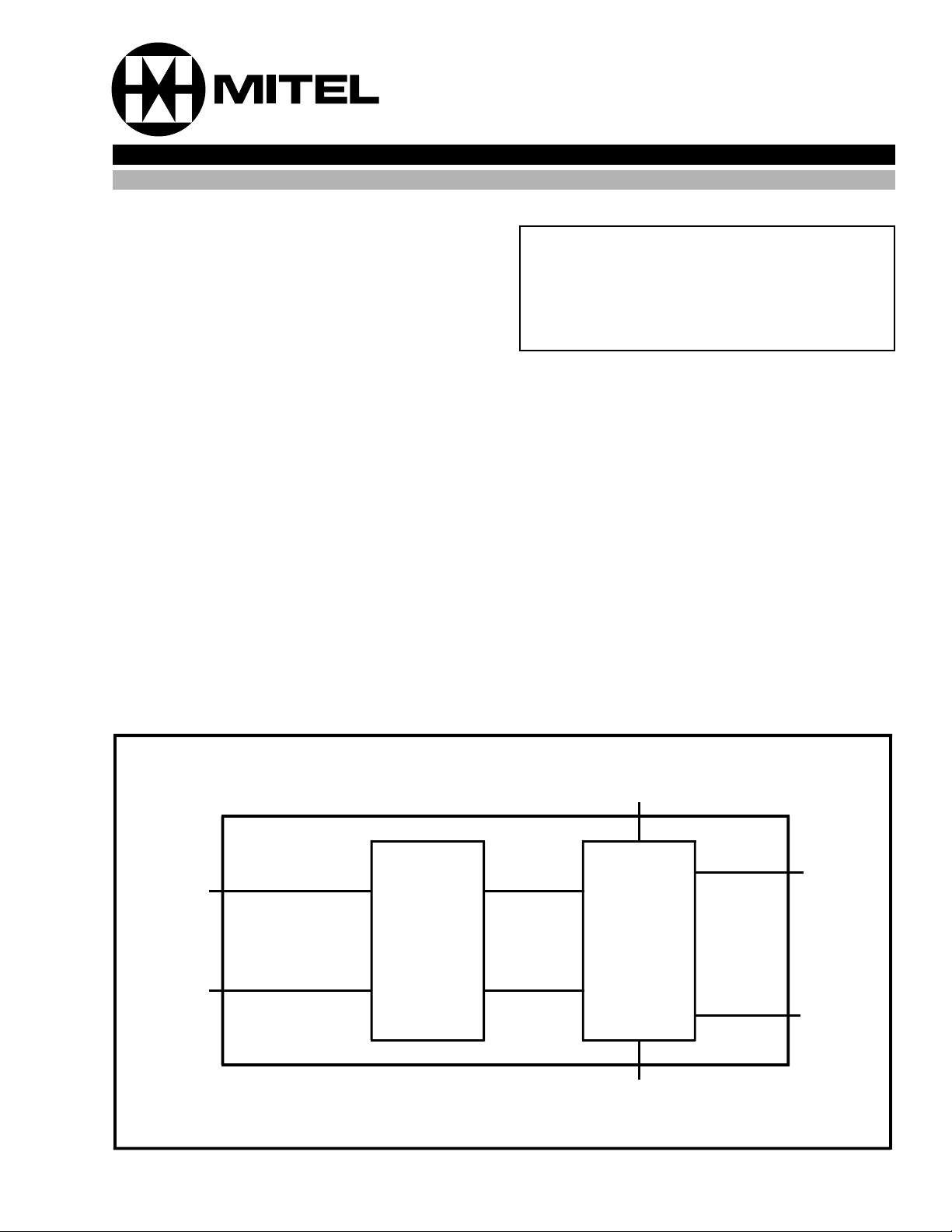
RXout -
RXout +
TXin +
Compensator
Circuit
Precanceller
TXin -
Figure 1 - Functional Block Diagram
XFM +
XFM -
9-29
Page 2
MH89101 Advance Information
TXin +
XFM +
RXout +
RXout -
XFM TXin -
(component side)
1
2
3
4
5
6
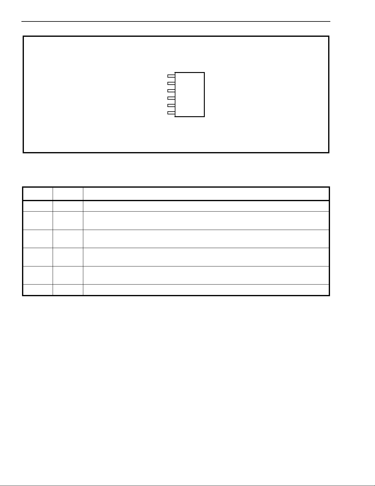
Figure 2 - Pin Connections
Pin Description
Pin # Name Description
1TX
2XFM+Transformer . Node of the 2 to 4 wire converter which must be connected to the primary of
3RX
4RX
5XFM-T ransformer. Node of the 2 to 4 wire converter which must be connected to the primary of
Transmit Line Signal Input. Must be connected to the L
in+
output of the DSLIC.
out+
the line transformer.
Receive Line Signal Output. Output of the compensator circuit which must be connected
out+
to the L
Receive Line Signal Output. Output of the compensator circuit which must be connected
out-
to the L
input of the DSLIC.
in+
input of the DSLIC.
in-
the line transformer.
6TX
Transmit Line Signal Input. Must be connected to the L
in-
output of the DSLIC.
out-
9-30
Page 3
Advance Information MH89101
Functional Description
The termination network is an all passive circuit
which allows the DSLIC to interface to the DSL
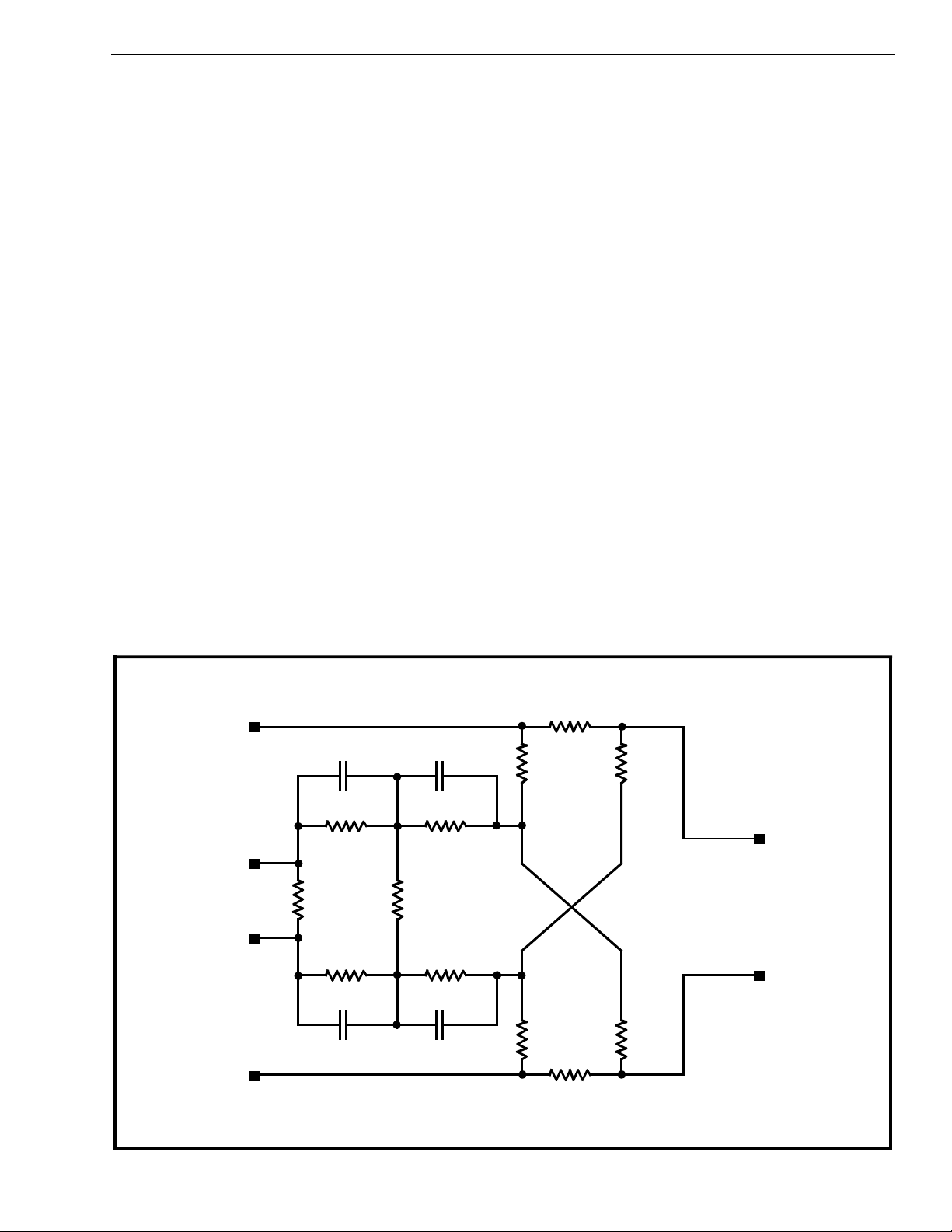
through a pulse transformer. The equivalent circuit
of the Passive Line Termination Network can be
seen in Figure 3 below.
The PLT consists of two blocks which includes a
hybrid network and a compensator circuit.
The hybrid network is a 2 to 4 wire converter which
provides a large degree of precancellation of the
near end signal while presenting little attenuation to
the far end signal. This is performed using a
summing junction which effectively subtracts the
transmit signal from the receive path.
The compensator circuit, in conjunction with the
transformer, acts as a highpass filter reducing the
low frequency content in the received line signal.
This, in turn, decreases the effects of ISI and near
end echo, and improves the transceiver performance.
Ty pical A pplicat ion
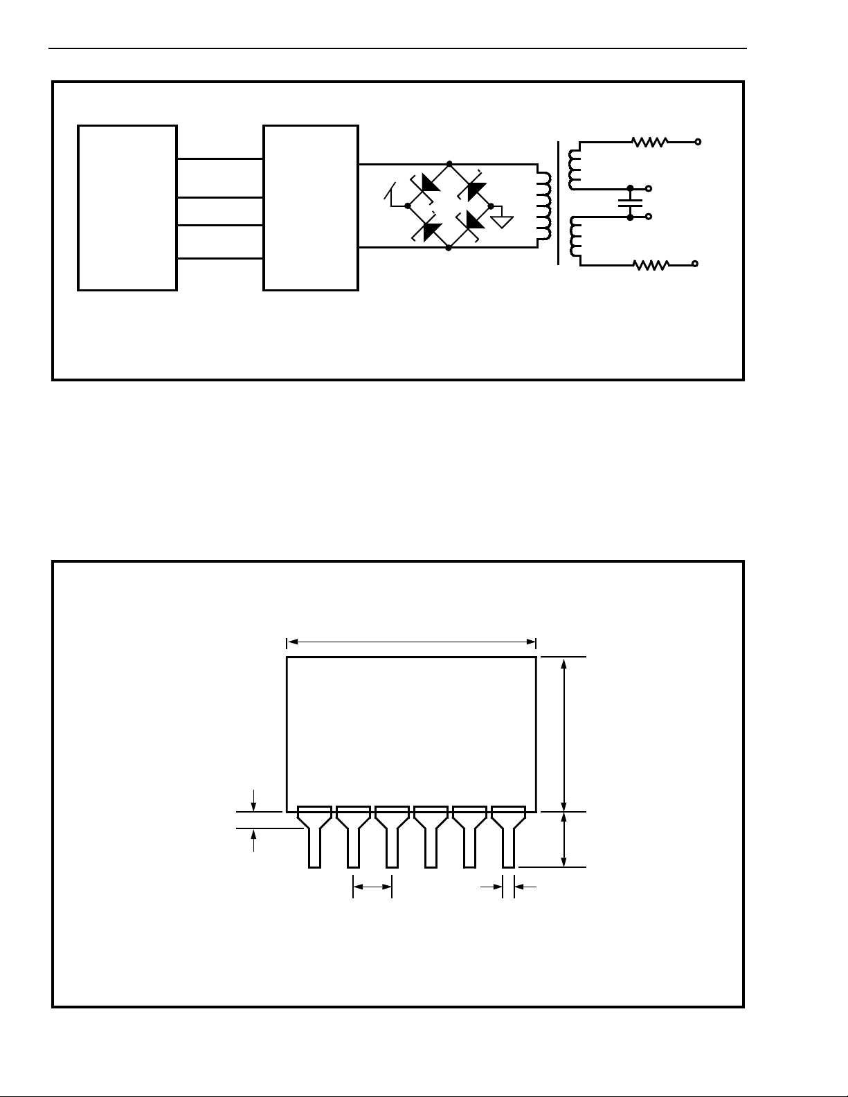
Figure 4 shows a typical connection diagram of the
MT8910 DSLIC and the Passive Line Termination
Circuit. As seen in Figure 4, the PLT is positioned
between the DSLIC and the line pulse transformer.
Two series protection resistors on the secondary of
the line pulse transformer are used to dissipate any
extraneous energy which may be induced onto the
transm issi on line.
RX
RX
TX
OUT +
OUT -
TX
IN +
IN -
R
= 30.2 Ω
s
680 pF
130 KΩ
68K2 Ω
130 KΩ
680 pF
3.3 nF
20 KΩ
7K8 Ω
20 KΩ
3.3 nF
R
b1
1K6 Ω
R
b1
1K6 Ω
= 30.2 Ω
R
s
Figure 3 - Passive Line Termination Network
R
b2
1K Ω
R
b2
1K Ω
XFM +
XFM -
9-31
Page 4
MH89101 Advance Information
MT8910
L
out +
L
in +
L
in -
L
out -
Note: D1-D4 Schottky Diodes MUR 105
TX
RX
RX
TX
MH89101
in +
XFM +
out +
out -
XFM -
in -
+ 5V
D1
D3
D2
7mH
D4
Figure 4 - Typical Connection Diagram
1:1.3
5.5 mH
µF
1.5
5.5 mH
10Ω ±
10Ω ±
10%
Power
Feed/Extract
10%
1.45 mm max.
(0.058")
NOTE:
All dimensions mm (inches)
15.24 mm ± 0.51 mm
(0.6" ± 0.020")
1
2.54 mm ± 0.254 mm
(0.1" ± 0.010")
0.5 mm no minal
(0.020")
Figure 5 - Ph ysic al Dime nsions
10.67 mm ± 0.51 mm
(0.42" ± 0.020")
4.45 mm ± 0.39 mm
(0.175" ± 0.015")
9-32
 Loading...