

Page 1
WJ Communications, Inc. • Phone: 1-800-WJ1-4401 • FAX:408-577-6620 • e-mail:sales@wj.com • Web site: www.wj.com
December 2001
MH101
Product Description
The MH101 is a passive GaAs MESFET mixer
that provides high dynamic range performance
in a low cost SOIC-8 package. WJ’s MH101
uses patented techniques to realize greater than
+30 dBm Input IP3 at an LO drive level of
+17 dBm.
This single monolithic integrated circuit does
not require any external baluns, bias, matching,
or decoupling elements. The on-chip diplexer
affords good matching on the RF and IF ports.
Typical applications include frequency up/down
conversion, modulation and demodulation for
receivers and transmitters used in 3G UMTS
systems.
Product Features
•
+30 dBm Input IP3
• No External Matching Elements
Required
• RF 1900-2200 MHz
• LO 1700-2150 MHz
•
IF 50-200 MHz
• +17 dBm Drive Level
• Low Cost SOIC-8 Package
•
No External Bias Required
Absolute Maximum Ratings
1
Parameter Rating
Operating Case Temperature -40 to +85°C
Storage Temperature -65 to +100°C
Maximum Input LO Power
2
+21 dBm
1. Operation of this device above any of these parameters may cause permanent damage.
2.Total sum of LO port and RF port power should not to exceed +23 dBm.
Ordering Information
Part No. Description
MH101 High Dynamic Range MMIC Mixer
(Available in tape and reel)
MH101-PCB Fully Assembled Application Circuit
High Dynamic Range MMIC Mixer
Specifications
Parameter Units Minimum Typical Maximum Condition
Frequency Range:
RF MHz 1900 2200
LO MHz 1700 2150
IF MHz 50 200
SSB Conversion Loss dB 9.0 10.5
Noise Figure dB 9.5
Input IP3 dBm +30
Input P1dB dBm +16
Isolation:
L-R dB 28
L-I dB 37
R-I dB 18
Return Loss:
RF Port dB 15
LO Port dB 12
IF Port dB 20
LO Drive Level dBm +17
Data was taken using the application board in a 50 Ω system, with a low side LO at +17 dBm in a downconvertering applicaion at 25°C.
Input IP3 was measured with two tones with an input power of +5 dBm/tone separated by 1 MHz.
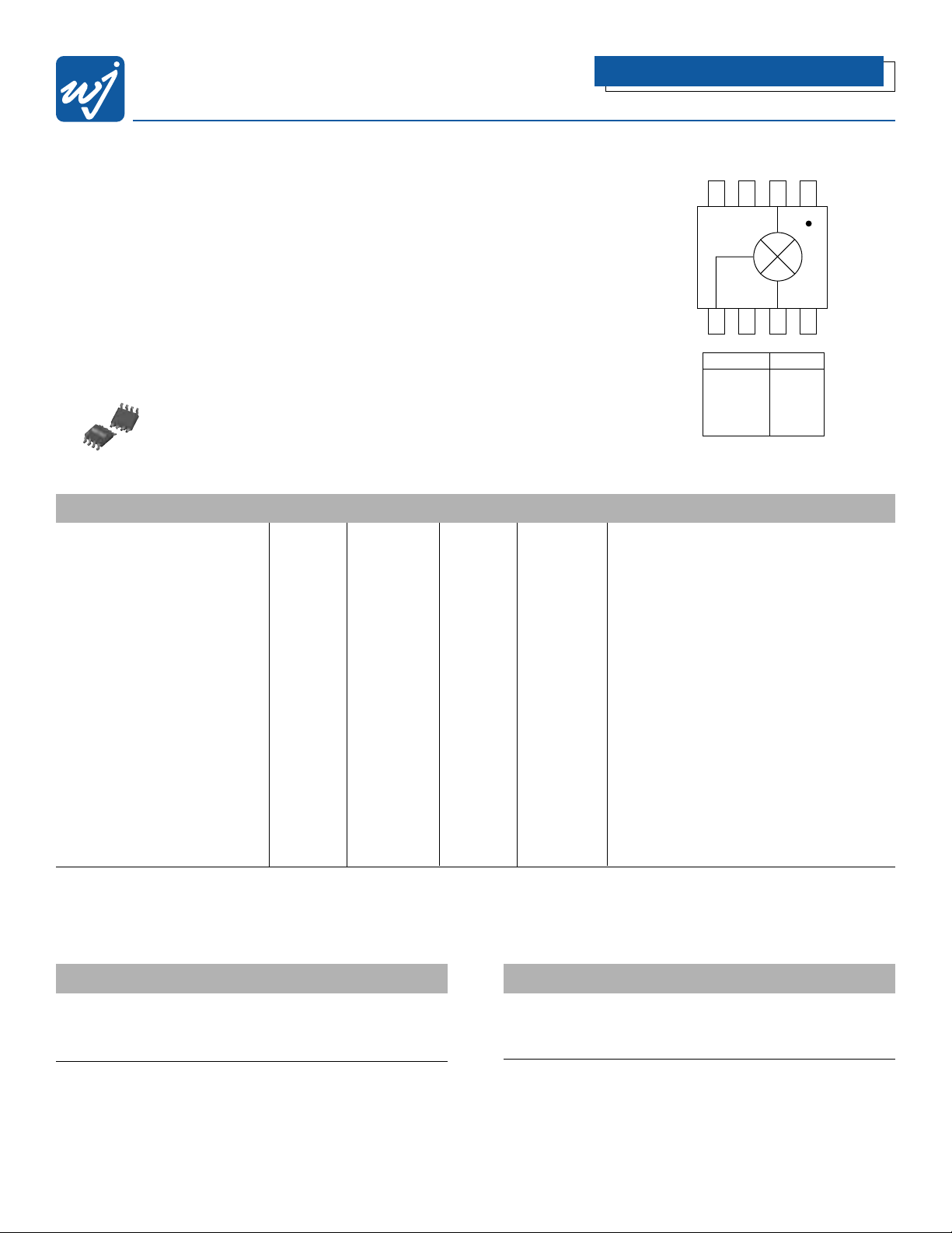
Functional Diagram
The Communications Edge
™
Advanced Product Information
Actual Size
4321
5678
Function Pin No.
RF 7
LO 2
IF 5
Ground 1,3,4,6,8
Page 2
WJ Communications, Inc. • Phone: 1-800-WJ1-4401 • FAX:408-577-6620 • e-mail: sales@wj.com • Web site: www.wj.com
December 2001
MH101
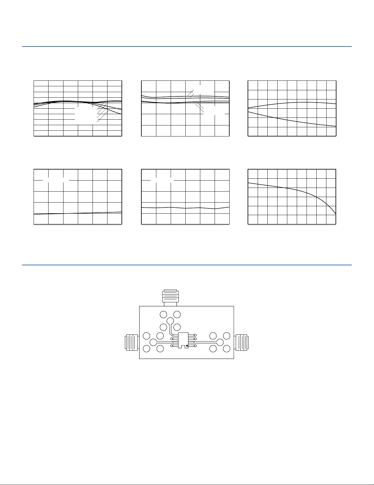
Performance Charts
Application Circuit
Advanced Product Information
Data was taken using the application board in a 50 Ω system, with a low side LO at +17 dBm in a downconvertering applicaion at 25°C.
Input IP3 was measured with two tones with an input power of +5 dBm/tone separated by 1 MHz.
Input IP3 vs RF Frequency
35
34
33
32
31
30
29
28
27
Input Intercept Point (dBm)
26
25
1900 1950 2000 2050 2100 2150 2200
IF = 200 MHz
IF = 150 MHz
IF = 100 MHz
IF = 50 MHz
RF Frequency (MHz)
IF Return Loss vs IF Frequency
0
RF = 2000 MHz
5
10
15
IF Return Loss (dB)
20
25
150 200175 225 250 275 300
IF Frequency (MHz)
Conversion Loss vs RF Frequency
9.2
IF = 200 MHz
9.0
8.8
8.6
Conversion Loss (dB)
8.4
8.2
1900 1950 2000 2050 2100 2150 2200
RF Frequency (MHz)
IF = 150 MHz
IF = 100 MHz
IF = 50 MHz
RF Return Loss vs RF Frequency
0
IF = 100 MHz
5
10
15
RF Return Loss (dB)
20
25
1900 1950 2000 2050 2100 2150 2200
RF Frequency (MHz)
Isolation vs LO Frequency
50
45
40
35
Isolation (dB)
30
25
20
1700 18001750 1850 1900 1950 2000 2050 2100 2150
LO Frequency (MHz)
L-I
L-R
LO Return Loss vs LO Frequency
0
5
10
15
20
LO Return Loss (dB)
25
30
1700 18001750 19001850 1950 2050 2100 2150 2200
LO Frequency (MHz)
IF
RF LO
Page 3

WJ Communications, Inc. • Phone: 1-800-WJ1-4401 • FAX:408-577-6620 • e-mail: sales@wj.com • Web site: www.wj.com
December 2001
LO Driver for MH101 Applications
MH101
Advanced Product Information
Summary:
Various times it may be difficult to apply a +17 dBm required LO signal to drive
WJ Communications' MH101 mixer. This application note offers a suggested LO
driver curcuit so that only +5 dBm of power is required from an external LO source
to drive any of WJ's new MMIC mixers: the MH1, MH101, or MH102. (Two LO
driver circuits can also be cascaded together if only -8 dBm is available from an LO
source.)
The LO driver using WJ’s AM1 amplifier is suitable for any LO signal in the
frequency band of 1450-2200 MHz. Only a single supply is needed to power the
driver with 4.5 V at 75 mA. In addition, an integrated high pass filter is suggested,
but not required, in the application circuit to reject and limit IF noise that might
be incident into the LO port of the mixer. The filter provides excellent rejection at
IF frequencies up to 450 MHz.
1. All specification parameters were tested at 25°C.
2. All components are 0603 size. All components are standard 5% tolerance parts. Toko LL1608-FH chip inductors and AVX capacitors were used in the design.
3.The optional high pass filter can be substituted with a series 68 pF DC blocking capacitor if not used.
4. Please refer to the AM1 datasheet for specifications and mounting information pertaining to the AM1.
Typical Specification Parameters
1
Frequency (MHz) 1450-2200
RF Input Power (dBm) +5
Min RF Output Power (dBm) +17
S21 - Small Signal Gain (dB) 13
S11 - Input Return Loss (dB) -12
S22 - Output Return Loss (dB) -15
Maximum RF Input Power (dBm) +7
200 MHz rejection (dBc) 40
Bias +4.5 V at 75 mA
Suggested System Configuration
1450-2200 MHz
LO Driver
Circuit Schematic
2
MH101 Mixer
RF IF
LO Driver
LO Source
+5 dBm
HPFAM1
LO
+17 dBm
Small-signal S-parameters vs Frequency
20
10
0
-10
dB
-20
-30
-40
0 500 1000 1500 2000 2500 3000
S21
S11
S22
S12
Frequency (MHz)
DC BIAS
PIN 3
4
PIN 2, 4
V = +4.5 V
75 mA
L = 22 nH
C = 3.9 pF
High Pass Filter
C = 3.9 pF
L = 5.6 nH
3
INTO MIXER
LO PORT
+17 dBm
LO SOURCE
+5 dBm
50 deg @ 2 GHz
C = 1 pF
Z0 = 50 Ohm
C = 68 pF
PIN 1
AM1
SOT-89
Page 4

Outline Drawing
WJ Communications, Inc. • Phone: 1-800-WJ1-4401 • FAX:408-577-6620 • e-mail: sales@wj.com • Web site: www.wj.com
December 2001
This document contains information on a new product.
Specifications and information are subject to change without notice.
Caution! ESD sensitive device.
MH101
Advanced Product Information
Land Pattern
Mounting Configuration
 Loading...