

Datasheet MF-MSMF010, MF-MSMF014, MF-MSMF020, MF-MSMF030, MF-MSMF050 Datasheet (BOURNS)
...Page 1
Specifications are subject to change without notice.
Customers should verify actual device performance in their specific applications.
Electrical Characteristics
Max. Time
Tripped
I
hold
I
trip
To Tr i p
Power
Resistance
Dissipation
Model
Amperes Ohms Amperes Seconds Watts
V max. I max.
at 23 °C at 23 °C at 23 °C at 23 °C at 23 °C
Volts Amps
Hold Trip RMin.
R
1Max. Typ.
MF-MSMF010 60.0 40 0.10 0.30 0.70 15.00 0.5 1.50 0.8
MF-MSMF014 60.0 40 0.14 0.34 0.40 6.50 1.5 0.15 0.8
MF-MSMF020 30.0 80 0.20 0.40 0.40 6.00 6.0 0.06 0.8
MF-MSMF030 30.0 10 0.30 0.60 0.30 3.00 8.0 0.10 0.8
MF-MSMF050 15.0 100 0.50 1.00 0.15 1.00 8.0 0.15 0.8
MF-MSMF075 13.2 100 0.75 1.50 0.11 0.45 8.0 0.20 0.8
MF-MSMF075/24 24.0 40 0.75 1.50 0.11 0.45 8.0 0.20 0.8
MF-MSMF110 6.0 100 1.10 2.20 0.04 0.21 8.0 0.30 0.8
MF-MSMF110/16 16.0 100 1.10 2.20 0.04 0.21 8.0 0.30 0.8
MF-MSMF125 6.0 100 1.25 2.50 0.035 0.14 8.0 0.40 0.8
MF-MSMF150 6.0 100 1.50 3.00 0.03 0.120 8.0 0.5 0.8
MF-MSMF160 8.0 100 1.60 2.80 0.035 0.099 8.0 2.0 0.8
MF-MSMF200 6.0 100 2.00 4.00 0.020 0.100 8.0 3.0 0.8
MF-MSMF250/16 16.0 100 2.50 5.00 0.015 0.100 8.0 5.0 0.8
MF-MSMF260 6.0 100 2.60 5.20 0.015 0.080 8.0 5.0 0.8
Operating Temperature ......................................-40 °C to +85 °C
Maximum Device Surface Temperature
in Tripped State ................................................125 °C
Passive Aging......................................................+85 °C, 1000 hours ....................................±5 % typical resistance change
Humidity Aging....................................................+85 °C, 85 % R.H. 1000 hours ..................±5 % typical resistance change
Thermal Shock ....................................................+85 °C to -40 °C, 20 times ........................±10 % typical resistance change
Solvent Resistance ............................................MIL-STD-202, Method 215 ........................No change
Vibration ..............................................................MIL-STD-883C, Method 2007.1, ................No change
Condition A
Environmental Characteristics
Test Test Conditions Accept/Reject Criteria
Visual/Mech.....................................Verify dimensions and materials ....................................Per MF physical description
Resistance ......................................In still air @ 23 °C............................................................Rmin ≤ R ≤ R1max
Time to Trip ....................................At specified current, Vmax, 23 °C ..................................T ≤ max. time to trip (seconds)
Hold Current ..................................30 min. at Ihold ..............................................................No trip
Trip Cycle Life ................................Vmax, Imax, 100 cycles ..................................................No arcing or burning
Trip Endurance................................Vmax, 48 hours ..............................................................No arcing or burning
Solderability ....................................ANSI/J-STD-002 ............................................................95 % min. coverage
UL File Number ..................................E174545
http://www.ul.com/ Follow link to Certifications, then UL File No., enter E174545
CSA File Number................................CA110338
http://directories.csa-international.org/ Under “Certification Record” and “File Number” enter 110338-0-000
TÜV Certificate Number......................R 02057213
http://www.tuvdotcom.com/ Follow link to “other certificates”, enter File No. 2057213
Test Procedures And Requirements For Model MF-MSMF Series
MF-MSMF Series - PTC Resettable Fuses
Features
■ 100 % compatible with all previous
generations of 1812 SMT devices
■ Compatible with Pb and Pb-free solder
reflow profiles
■ Surface mount packaging for automated
assembly
■ Agency recognition:
Applications
High Density Circuit Board Applications:
■ Hard disk drives
■ PC motherboards
■ PC peripherals
■ Point-of-sale (POS) equipment
■ PCMCIA cards
■ USB ports
TV Rheinland
NEW!
查询MF-MSMF010供应商
Page 2
Specifications are subject to change without notice.
Customers should verify actual device performance in their specific applications.
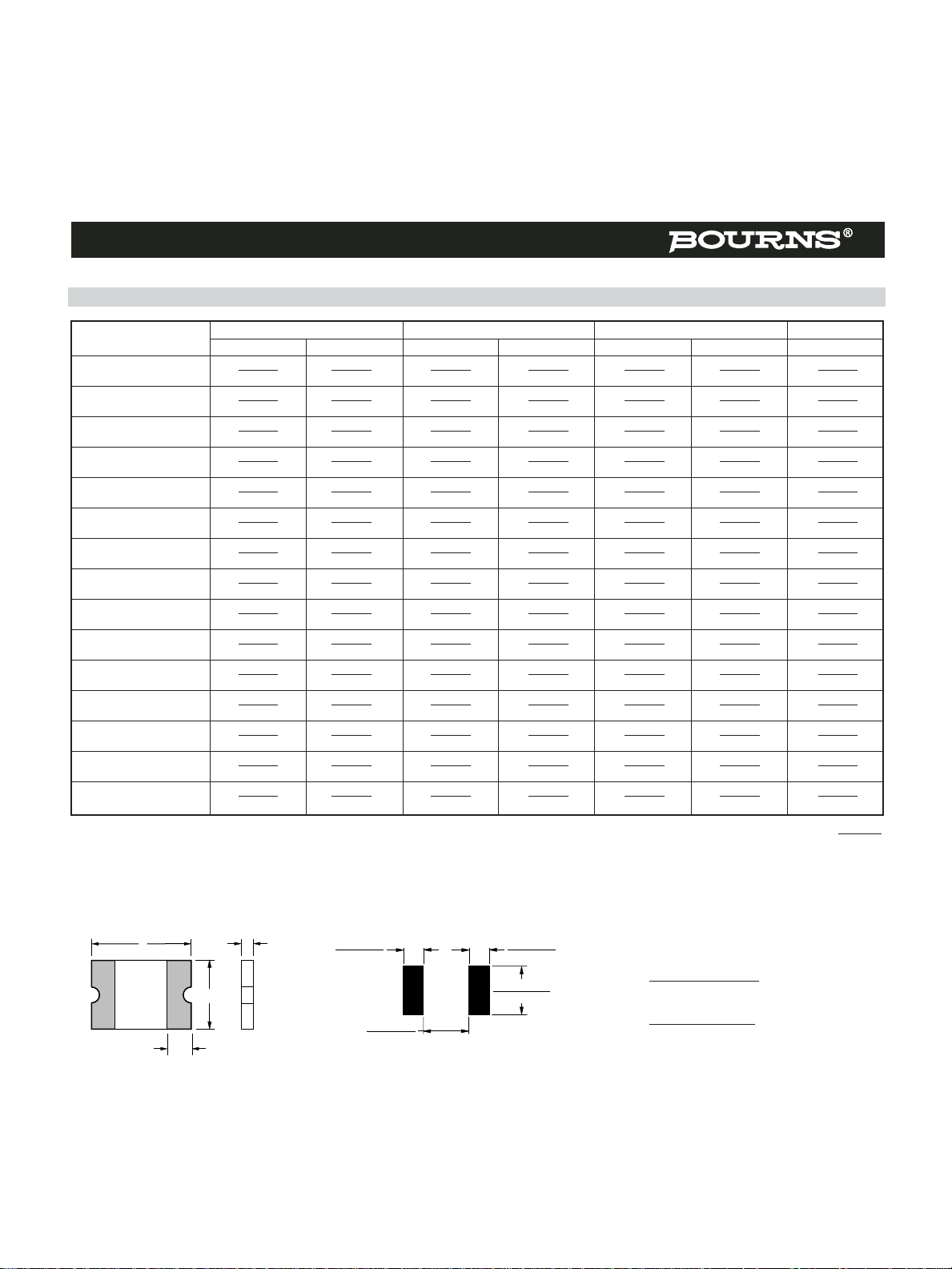
Product Dimensions
Packaging:
MF-MSMF010 through MF-MSMF030 = 1500 pcs. per reel.
MF-MSMF050 through MF-MSMF200 & MF-MSMF260 = 2000 pcs. per reel.
MF-MSMF250/16 = 1000 pcs. per reel.
MF-MSMF Series - PTC Resettable Fuses
ABCD
Model
Min. Max. Min. Max. Min. Max. Min.
MF-MSMF010
4.37 4.73 3.07 3.41 0.70 1.10 0.30
(0.172) (0.186) (0.121) (0.134) (0.028) (0.043) (0.012)
MF-MSMF014
4.37 4.73 3.07 3.41 0.70 1.10 0.30
(0.172) (0.186) (0.121) (0.134) (0.028) (0.043) (0.012)
MF-MSMF020
4.37 4.73 3.07 3.41 0.70 1.10 0.30
(0.172) (0.186) (0.121) (0.134) (0.028) (0.043) (0.012)
MF-MSMF030
4.37 4.73 3.07 3.41 0.70 1.10 0.30
(0.172) (0.186) (0.121) (0.134) (0.028) (0.043) (0.012)
MF-MSMF050
4.37 4.73 3.07 3.41 0.55 0.85 0.30
(0.172) (0.186) (0.121) (0.134) (0.015) (0.033) (0.012)
MF-MSMF075
4.37 4.73 3.07 3.41 0.55 0.85 0.30
(0.172) (0.186) (0.121) (0.134) (0.015) (0.033) (0.012)
MF-MSMF075/24
4.37 4.73 3.07 3.41 0.55 0.85 0.30
(0.172) (0.186) (0.121) (0.134) (0.015) (0.033) (0.012)
MF-MSMF110
4.37 4.73 3.07 3.41 0.45 0.75 0.30
(0.172) (0.186) (0.121) (0.134) (0.018) (0.030) (0.012)
MF-MSMF110/16
4.37 4.73 3.07 3.41 0.45 0.75 0.30
(0.172) (0.186) (0.121) (0.134) (0.018) (0.030) (0.012)
MF-MSMF125
4.37 4.73 3.07 3.41 0.55 0.85 0.30
(0.172) (0.186) (0.121) (0.134) (0.015) (0.033) (0.012)
MF-MSMF150
4.37 4.73 3.07 3.41 0.55 0.85 0.30
(0.172) (0.186) (0.121) (0.134) (0.015) (0.033) (0.012)
MF-MSMF160
4.37 4.73 3.07 3.41 0.55 0.85 0.30
(0.172) (0.186) (0.121) (0.134) (0.015) (0.033) (0.012)
MF-MSMF200
4.37 4.73 3.07 3.41 0.55 0.85 0.30
(0.172) (0.186) (0.121) (0.134) (0.015) (0.033) (0.012)
MF-MSMF250/16
4.37 4.73 3.07 3.41 1.00 2.00 0.30
(0.172) (0.186) (0.121) (0.134) (0.039) (0.078) (0.012)
MF-MSMF260
4.37 4.73 3.07 3.41 0.48 0.85 0.30
(0.172) (0.186) (0.121) (0.134) (0.019) (0.033) (0.012)
Additional Features
■ Standard 4532 mm (1812 mils) footprint
■ Symmetrical design
■ Patents pending
MM
(INCHES)
UNIT =
Terminal material:
Electroless Ni under immersion Au
Termination pad solderability:
Standard Au finish:
Meets ANSI/J-STD-002 Category 2.
Optional Sn finish:
Meets ANSI/J-STD-002 Category 3.
Recommended Storage:
40 °C max./70 % RH max.
A
B
C
Top and Bottom View Side View
D
Recommended Pad Layout
3.2 ± 0.1
(0.126 ± .004)
2.7 ± 0.1
(.106 ± .004)
1.5 ± 0.05
(.059 ± .002)
1.5 ± 0.05
(.059 ± .002)
Page 3

Specifications are subject to change without notice.
Customers should verify actual device performance in their specific applications.
How to Order
MF - MSMF 075/24 T - 2
Multifuse®Product
Designator
Series
MSMF = 4532 mm (1812 mils)
Surface Mount Component
Hold Current, I
hold
010-260 (0.10 Amps - 2.60 Amps)
Higher Voltage Option
__ = Standard Voltage
/16 = 16 Volt Rated
/24 = 24 Volt Rated
Optional Terminal Finish
__ = Standard Au Finish
T = Optional Sn Finish
Packaging
Packaged per EIA 481-1
-2 = Tape and Reel
Typical Time to Trip at 23 ˚C
MF-MSMF Series - PTC Resettable Fuses
Typical Part Marking
Represents total content. Layout may vary.
PART IDENTIFICATION EXAMPLES:
MF-MSMF050 = 50
MF-MSMF075 = 75
MF-MSMF110 = 11
MF-MSMF150 = 15
DATE CODE:
WEEK 1 AND 2 OF 2003 = 3A
WEEK 51 AND 52 OF 2003 = 3Z
MANUFACTURER'S
TRADEMARK
113G
Solder Reflow Recommendations
Notes:
• MF-MSMF models cannot be wave soldered.
• If reflow temperatures exceed the recommended profile, devices may not meet the performance
requirements.
• Compatible with Pb and Pb-free solder reflow profiles.
The Time to Trip curves represent typical performance of a device in a simulated application
environment. Actual performance in specific customer applications may differ from these values due
to the influence of other variables.
100
MF-MSMF200
MF-MSMF010
10
MF-MSMF030
1
0.1
Time to Trip (Seconds)
0.01
0.001
0.1
MF-MSMF014
MF-MSMF020
MF-MSMF075/24
MF-MSMF050
1 10 100
MF-MSMF260
MF-MSMF250/16
MF-MSMF160
MF-MSMF150
MF-MSMF125
MF-MSMF110
MF-MSMF075
MF-MSMF110/16
Fault Current (Amps)
300
250
200
150
100
Temperature (°C)
50
Preheating Soldering Cooling
0
160–220
10–20
Time (seconds)
120
Page 4

Specifications are subject to change without notice.
Customers should verify actual device performance in their specific applications.
MF-MSMF Series - PTC Resettable Fuses
Thermal Derating Chart - I
hold
/ I
trip
(Amps)
Ambient Operating Temperature
Model
-40 ˚C -20 ˚C 0 ˚C 23 ˚C 40 ˚C 50 ˚C 60 ˚C 70 ˚C 85 ˚C
MF-MSMF010 0.16 / 0.32 0.14 / 0.28 0.12 / 0.24 0.11 / 0.22 0.08 / 0.16 0.07 / 0.14 0.06 / 0.12 0.05 / 0.10 0.03 / 0.06
MF-MSMF014 0.23 / 0.52 0.19 / 0.45 0.17 / 0.40 0.14 / 0.34 0.12 / 0.29 0.10 / 0.25 0.09 / 0.23 0.08 / 0.21 0.06 / 0.16
MF-MSMF020 0.29 / 0.58 0.26 / 0.52 0.23 / 0.46 0.20 / 0.40 0.17 / 0.34 0.15 / 0.30 0.14 / 0.28 0.12 / 0.24 0.10 / 0.20
MF-MSMF030 0.44 / 0.88 0.39 / 0.78 0.35 / 0.70 0.30 / 0.60 0.26 / 0.52 0.23 / 0.46 0.21 / 0.42 0.18 / 0.36 0.15 / 0.30
MF-MSMF050 0.77 / 1.54 0.68 / 1.36 0.59 / 1.18 0.50 / 1.00 0.44 / 0.88 0.40 / 0.80 0.37 / 0.74 0.33 / 0.66 0.29 / 0.58
MF-MSMF075 1.15 / 2.30 1.01 / 2.02 0.88 / 1.76 0.75 / 1.50 0.65 / 1.30 0.60 / 1.20 0.55 / 1.10 0.49 / 0.98 0.43 / 0.86
MF-MSMF075/24 1.15 / 2.30 1.01 / 2.02 0.88 / 1.76 0.75 / 1.50 0.65 / 1.30 0.60 / 1.20 0.55 / 1.10 0.49 / 0.98 0.43 / 0.86
MF-MSMF110 1.59 / 3.18 1.43 / 2.86 1.26 / 2.52 1.10 / 2.20 0.95 / 1.90 0.87 / 1.74 0.80 / 1.60 0.71 / 1.42 0.60 / 1.20
MF-MSMF110/16 1.59 / 3.18 1.43 / 2.86 1.26 / 2.52 1.10 / 2.20 0.95 / 1.90 0.87 / 1.74 0.80 / 1.60 0.71 / 1.42 0.60 / 1.20
MF-MSMF125 1.80 / 3.61 1.63 / 3.25 1.43 / 2.86 1.25 / 2.50 1.08 / 2.16 0.99 / 1.98 0.91 / 1.82 0.81 / 1.62 0.68 / 1.36
MF-MSMF150 2.17 / 4.34 1.95 / 3.90 1.72 / 3.44 1.50 / 3.00 1.30 / 2.59 1.18 / 2.37 1.09 / 2.18 0.97 / 1.94 0.82 / 1.64
MF-MSMF160 2.30 / 5.00 2.20 / 4.40 1.90 / 3.80 1.60 / 2.80 1.45 / 2.90 1.30 / 2.60 1.15 / 2.30 1.03 / 2.06 0.91 / 1.82
MF-MSMF200 3.08 / 5.40 2.71 / 4.74 2.35 / 4.11 2.00 / 3.50 1.80 / 3.15 1.60 / 2.80 1.50 / 2.63 1.40 / 2.40 1.25 / 2.10
MF-MSMF250/16 3.9 / 7.8 3.42 / 6.84 2.96 / 5.92 2.50 / 5.00 2.24 / 4.48 1.98 / 3.96 1.85 / 3.70 1.29 / 2.58 0.94 / 1.88
MF-MSMF260 4.00 / 7.98 3.52 / 7.01 3.06 / 6.09 2.60 / 5.15 2.34 / 4.64 2.08 / 4.13 1.95 / 3.87 1.39 / 2.74 1.04 / 2.05
MF-MSMF SERIES, REV. C, 04/04
Circuit Protection Division
Asia-Pacific:
Tel: +886-2 2562-4117
Fax: +886-2 2562-4116
Europe:
Tel: +41-41 768 5555
Fax: +41-41 768 5510
North America:
Tel: +1-909 781-5500
Fax: +1-909 781-5700
Tel: +1-951 781-5500 (after 7/17/04)
Fax: +1-951 781-5700 (after 7/17/04)
www.bourns.com
Page 5

MF-MSMF010 - MF-MSMF030 MF-MSMF050 - MF-MSMF260 MF-MSMF250/16
Tape Dimensions per EIA-481-1 per EIA 481-1 per EIA 481-1
W
P
0
P
1
P
2
A
0
B
0
B1max.
D
0
F
E
1
E2min.
T max.
T1max.
K
0
Leader min.
Trailer min.
Reel Dimensions
A max.
N min.
W
1
W
2
max.
Specifications are subject to change without notice.
Customers should verify actual device performance in their specific applications.
MF-MSMF Series Tape and Reel Specifications
B
1
N(HUB DIA.)
(MEASURED
AT HUB)
A
T
COVER
TAPE
K
0
T
1
A
0
W
2
(MEASURED
AT HUB)
W
1
P
1
B
0
F
D
0
P
2
P
0
E
2
E
1
W
UNIT =
MM
(INCHES)
12.0 ± 0.30
(0.472 ± 0.012)
4.0 ± 0.10
(0.157 ± 0.004)
8.0 ± 0.10
(0.315 ± 0.004)
2.0 ± 0.05
(0.079 ± 0.002)
3.58 ± 0.10
(0.141 ± 0.004)
4.93 ± 0.10
(0.194 ± 0.004)
5.5 ± 0.05
(0.217 ± 0.002)
1.75 ± 0.10
(0.069 ± 0.004)
1.30 ± 0.10
(0.051 ± 0.004)
1.5 + 0.10/-0.00
(0.059 + 0.004/-0)
12.4 + 2.0/-0.0
(0.488 + 0.079/-0.0)
5.9
(0.232)
10.25
(0.404)
0.6
(0.024)
0.1
(0.004)
390
(15.35)
160
(6.30)
185
(7.28)
50
(1.97)
18.4
(0.724)
12.0 ± 0.30
(0.472 ± 0.012)
4.0 ± 0.10
(0.157 ± 0.004)
8.0 ± 0.10
(0.315 ± 0.004)
2.0 ± 0.05
(0.079 ± 0.002)
3.66 ± 0.15
(0.144 ± 0.006)
4.98 ± 0.10
(0.196 ± 0.004)
5.5 ± 0.05
(0.217 ± 0.002)
1.75 ± 0.10
(0.069 ± 0.004)
0.95 ± 0.10
(0.037 ± 0.004)
1.5 + 0.10/-0.00
(0.059 + 0.004/-0)
12.4 + 2.0/-0.0
(0.488 + 0.079/-0.0)
5.9
(0.232)
10.25
(0.404)
0.6
(0.024)
0.1
(0.004)
390
(15.35)
160
(6.30)
185
(7.28)
50
(1.97)
18.4
(0.724)
12.0 ± 0.30
(0.472 ± 0.012)
4.0 ± 0.10
(0.157 ± 0.004)
8.0 ± 0.10
(0.315 ± 0.004)
2.0 ± 0.05
(0.079 ± 0.002)
3.43 ± 0.10
(0.135 ± 0.004)
4.83 ± 0.10
(0.190 ± 0.004)
5.5 ± 0.05
(0.217 ± 0.002)
1.75 ± 0.10
(0.069 ± 0.004)
1.70 ± 0.10
(0.067 ± 0.004)
1.5 + 0.10/-0.00
(0.059 + 0.004/-0)
12.4 + 2.0/-0.0
(0.488 + 0.079/-0.0)
5.9
(0.232)
10.25
(0.404)
0.6
(0.024)
0.1
(0.004)
390
(15.35)
160
(6.30)
185
(7.28)
50
(1.97)
18.4
(0.724)
 Loading...