

Page 1
Low Cost MMIC Mixer with Local Oscillator Amplifier, 0.8-1.0 GHz MD57-0001
g
g
g
MD57-0001
Low Cost MMIC Mixer with Local Oscillator
Amplifier, 0.8 GHz - 1.0 GHz
Features
• -5 to +5 dBm LO Drive Level
• High Isolation, 28 dB LO to RF
• Inexpensive SOT-26 Package
Description
The MD57-0001 is a floating FET mixer with an on-chip LO
amplifier. The LO drive for the MD57-0001 can range from -5 to
+5 dBm without severly impacting the mixer’s performance. The
MD57-0001 is ideally suited for cellular band communications
handsets’ that can provide only minimal amounts of LO drive.
Typical applications include frequency up/down conversion and
IQ modulation and demodulation in digital receivers and
transmitters.
The MD57-0001 utilizes a patented “floating-FET” architecture.
The on-chip LO amplifier allows the MD57-0001 to operate with
as little as -5 dBm of LO drive making it an ideal choice for low
power portable designs.
The MD57-0001 is fabricated using M/A-COM’s 0.5 micron low
noise GaAs MESFET process. This process features full
passivation for increased performance and reliability. The
MD57-0001 is 100% RF tested to ensure superior performance
specification compliance.
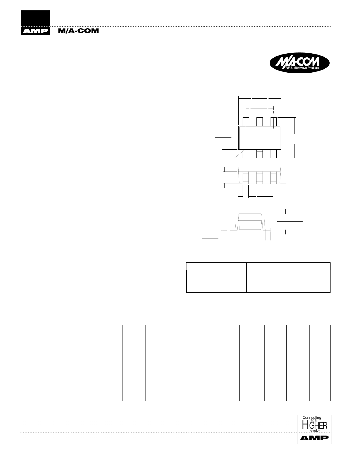
SOT-26
114±.008
.
2,9±0,2
.075±.008
1,90 ±0,2
+.008
.063
.031
0,79
.006
0,15
+.004
-.007
+0.10
-0.18
+.004
-.002
+0.10
-0.05
1,60
-.004
+0.20
-0.10
PIN # 1
16XY
+.004
.016
-.002
+0.10
0,40
-0.05
008 MIN
.
0,20 MIN
.110
±.008
2,80±0,2
.002±.002
0,05±0,05
+.008
043
.
-.004
+0.20
1,10
-0.10
Ordering Information
Part Number Package
MD57-0001 SOT-26, 6-Lead Plastic Packa
MD57-0001TR Forward Tape and Reel*
MD57-0001SMB Desi
ner’s Kit
e
*If a specific reel size is required, consult factory for part number.
Electrical Specifications
TA = +25°C, RF = 900MHz (-15 dBm), LO = 730MHz (-5 dBm), IF = 170MHz, V
1
= 2.7V, Typical I
DD
= 5mA
DD
Parameters Abbv. Test Conditions Units Min. Typ. Max.
Conversion Loss L
c
—dB—9.311
Isolation ISO LO to RF dB 20 28 —
LO to IF dB 10 12 —
RF to IF dB — 20 —
VSWR VSWR RF Port — — 2.0:1 —
LO Port — — 2.0:1 —
IF Port — — 2.0:1 —
Input 1 dB Compression P
Two Tone IM Ratio
1. IMR vs. RF drive can be calculated by the for m ula: IMR = [44 - 1.5(PIN)]
M/A-COM Division of AMP Incorporated ■ North America: Tel. (800) 366-2266, Fax (800) 618- 8883 ■ Asia/Pacific: Tel.+85 2 2111 8088, Fax +85 2 2111 8087
■
Europe: Tel. +44 (1344) 869 595, Fax+ 44 (1344) 300 020
www.macom.com
1
AMP and Connecting at a Higher Level are trademark s.
Specifications subject to change wit hout notice.
1dB
dBc Two tones at -10 dBm each;
RF Freq. = 900 MHz, LO = -5 dBm dBm — 14 —
dBc — 59 —
Tone spacin
= 1 MHz, IF = 170 MHz
V2.00
Page 2
Low Cost MMIC Mixer with Local Oscillator Amplifier, 0.8-1.0 GHz MD57-0001
g
g
g
g
g
Absolute Maximum Ratings
Parameter Ratings
Input RF/IF Power
Input LO Power
Operatin
Operatin
Stora
1. Exceeding these limits may cause permanent damage.
2. Ambient Temperature (T
3. Typical Thermal Resis tance (
Voltages
Temperature -30°C to +80°C
e Temperature -65°C to +150°C
condition.
2
2
2
) = + 25°C.
A
θ
) = 108°C/W at nomial bias
jc
1,3
+27 dBm
+17 dBm
VDD = +6 volts
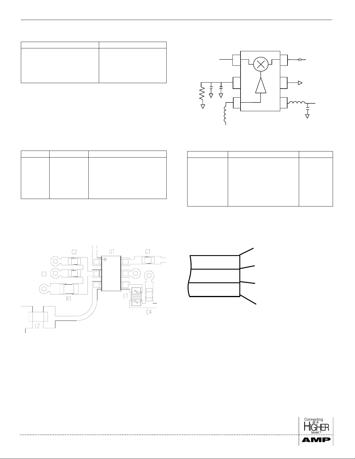
Pin Configuration
Pin No. Pin Name Description
1 RF Port RF Input/Output
2 Bias LO Amplifier Bias Resistor
3 LO Port LO Input
4V
DD
5 GND Ground
6 IF Port IF Input/Output
LO Amplifier V
DD
Functional Block Diagram
R1
RF
C2
1
C3
2
3
L2
LO
6
C1
5
L1
4
External Circuitry Parts List
Part Name Description Value
R1 LO Amplifier Bias Resistor
L1 LO Amplifier Bias Input 22 nH
L2 LO Port Matchin
C1 IF Port Matchin
C2 IF Bypass Capacitor 10 nF
C3 RF Bypass Capacitor 22 pF
C4 V
Bypass 47 pF
DD
IF
C4
200
10 nH
10 nF
V
DD
Ω
Recommended PCB Configuration
Layout View
Cross Section View
RF Traces & Components
RF Ground
DC Routing
Customer Defined
The PCB dielectric between RF traces and RF ground layers
should be chosen to reduce RF discontinuities between 50
lines and package pins. M/A-COM recommends an FR-4
dielectric thickness of 0.008” (0.2 mm) yielding a 50 Ω line
width of 0.015” (0.38 mm). The recommended metalization
thickness is 1 oz. Copper.
Ω
M/A-COM Division of AMP Incorporated ■ North America: Tel. (800) 366-2266, Fax (800) 618- 8883 ■ Asia/Pacific: Tel.+85 2 2111 8088, Fax +85 2 2111 8087
■
Europe: Tel. +44 (1344) 869 595, Fax+ 44 (1344) 300 020
www.macom.com
AMP and Connecting at a Higher Level are trademark s.
Specifications subject to change wit hout notice.
V2.00
Page 3

Low Cost MMIC Mixer with Local Oscillator Amplifier, 0.8-1.0 GHz MD57-0001
Spurious Table (dBc)
LO Harmonic (n) RF Harmonic (m)
0X
1X
2X
3X
4X
0X 1X 2X 3X 4X
-10 dBm X 4.1 44.9 69.5 79.7
0 dBm X 3.9 31.9 48.4 70.0
-10 dBm 13.8 0 47.6 82.0 76.6
0 dBm 22.9 0 35.1 73.0 83.8
-10 dBm 10.8 18.9 46.5 70.6 78.0
0 dBm 20.4 18.9 36.6 55.9 84.0
-10 dBm 12.1 23.8 41.5 76.9 77.1
0 dBm 22.7 23.8 31.0 63.1 74.0
-10 dBm 13.6 50.9 68.5 64.5 80.6
0 dBm 24.0 49.4 58.9 45.4 63.4
• The spurious table shows the spurious signals resulting from
the mixing of the RF and LO input signals assuming down
conversion.
• Mixing products are indicated relative to the IF level.
• The lower frequency mixing term is shown for two different
RF input levels.
• The RF frequency is 900 MHz, the LO frequency is 730
MHz.
[nFRF - mFLO] RF = -10 dBm
[nF
- mFLO] RF = 0 dBm
RF
Typical Performance Data
• Down Converter Application Test Conditions: RF=900 MHz, IF=170 MHz, LO=730 MHz (LO Power = -5dBm)
Conversion Loss vs. Frequency (IF = 170 MHz)
8
9
10
11
Conversion Loss (dB)
12
800 850 900 950 1000
RF Frequency (MHz)
30
25
20
15
Input IP3 (dBm)
10
800 850 900 950 10 00
RF Frequency (MHz)
Return Loss vs. Frequency
5
4
RF
LO
3
VSWR
2
1
0
600 700 800 900 1000
Frequency (MHz)
IsolationsIMR Plot
60
50
40
30
20
Isolation (dB)
10
0
600 700 80 0 900 1000
LO to IF
RF to IF
LO to RF
Frequency (MHz)
M/A-COM Division of AMP Incorporated ■ North America: Tel. (800) 366-2266, Fax (800) 618- 8883 ■ Asia/Pacific: Tel.+85 2 2111 8088, Fax +85 2 2111 8087
■
Europe: Tel. +44 (1344) 869 595, Fax+ 44 (1344) 300 020
www.macom.com
AMP and Connecting at a Higher Level are trademark s.
Specifications subject to change wit hout notice.
V2.00
Page 4
Low Cost MMIC Mixer with Local Oscillator Amplifier, 0.8-1.0 GHz MD57-0001
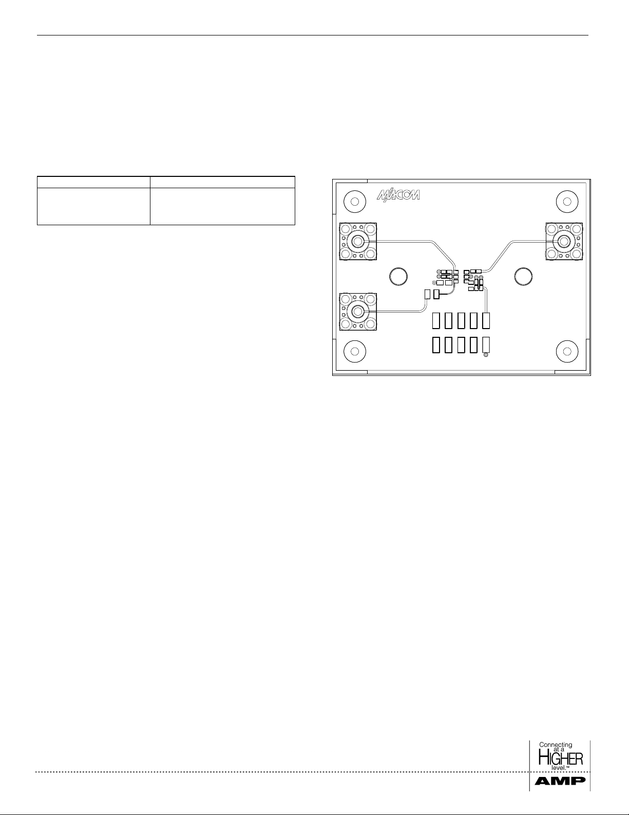
Designer’s Kit MD57-0001SMB
The MD57-0001SMB Designer’s Kit allows for immediate evaluation of M/A-COM’s MD57-0001. The Designer’s Kit consists of an
MD57-0001, an evaluation board, a floppy disk containing typical performance data and a DXF file of the recommended PCB layout.
The evaluation board consists of the recommended external surface mount circuitry and RF connectors mounted to a multi-layer PCB. The
MD57-0001SMB evaluation PCB is shown below with all functional ports labeled.
Evaluation PCB and RF Connector Losses MD57-0001SMB Evaluation PCB
Port Reference Approximate RF Loss
RF Port 0.14 dB @ 900 MHz
LO Port 0.14 dB @ 730 MHz
IF Port 0.04 dB @ 170 MHz
AV10328
REV A
RF
LO
978563
V
MSOP-8
IF
DD
GND
412
10
M/A-COM Division of AMP Incorporated ■ North America: Tel. (800) 366-2266, Fax (800) 618- 8883 ■ Asia/Pacific: Tel.+85 2 2111 8088, Fax +85 2 2111 8087
■
Europe: Tel. +44 (1344) 869 595, Fax+ 44 (1344) 300 020
www.macom.com
AMP and Connecting at a Higher Level are trademark s.
Specifications subject to change wit hout notice.
V2.00
 Loading...