

Page 1
Termination Insensitive Mixer,
1 MHz - 3.5 GHz
V 3.00
MD-/MDC-/MDS-169
Features
n Intermodulation Ratio is Insensitive to Port Mismatches
n VSWR: <2.0:1 Typical Midband
n Isolation: 35 dB Typical Midband
n Impedance: 50 Ohms Nominal
n Maximum Input Power: 350 mW Max @ 25°C, Derated
to 85°C @ 3.2 mW/°C
n LO Power: +24 dBm Max.
n MIL-STD-883 Screening Available
Description
The unique design of the termination insensitive mixer
(TIM) enables it to apply high reverse voltage to diodes
during their “off” phase, in the LO cycle. This allows for
higher power level performance with minimum distortion.
In addition the TIM has internal loads that provide a good
match and also absorb mixer generated LO frequency
terms. Combined, these features give the mixer its
insensitivity to external mismatches, plus superior VSWR.
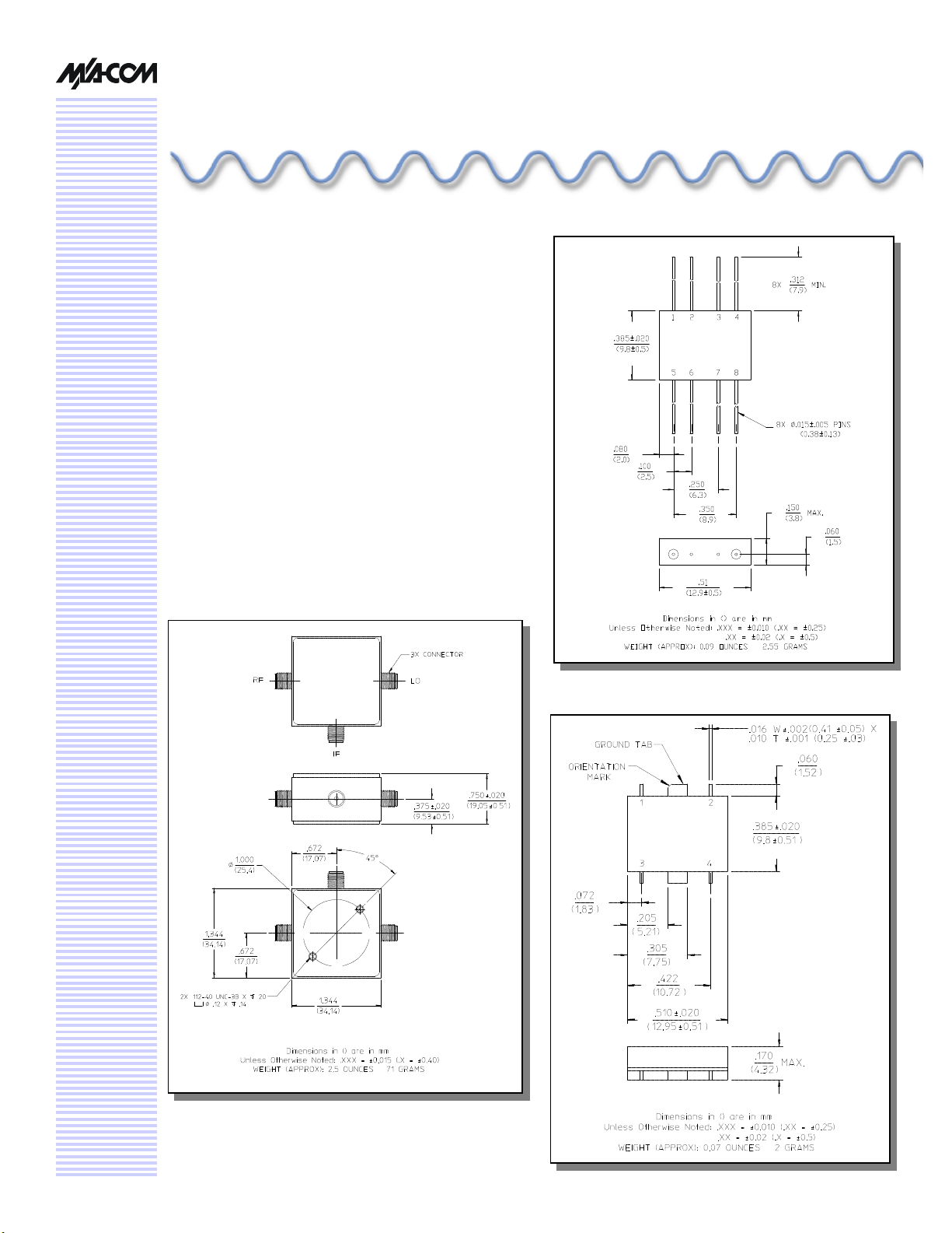
C-7 (MDC-169)
FP-2 (MD-169)
SF-1 (MDS-169)
Page 2
Termination-Insensitive Mixer, 1 MHz - 3.5 GHz
Electrical Specifications1(MD-/MDC-169): TA = -55°C to +85°C
Parameter Test Conditions Frequency Units Min Typ Max
MD-/MDC-/MDS-169
V 3.00
Frequency Range RF, LO Ports
Conversion Loss
Isolation LO to RF 5 - 1000 MHz
RF Input 1 dB Compression
SSB Noise Figure Within 1 dB of Conversion Loss
Typical Two-Tone IM
Ratio
3rd Order
Intermodulation Ratio
Degradation
1. All specifications apply when operated at +10 available LO power with 50 Ohm source and load impedance.
2. For IF Frequencies of 5 - 300 MHz and RF of –10 dBm or less.
3. For MDC-169, add 1.0 dB to conversion loss.
with a –10 dBm input, each input,
IF Port
5 - 1000 MHz 2
LO to IF 5 - 1000 MHz
RF to IF 10 - 500 MHz
1 dB Desensitization
Max
25 MHz and 35 MHz IF
@ IF VSWR 3:1 — dB — 3 —
0.001 - 3.5
5 - 1500
5 - 3000 MHz 3
1 - 3500 MHz
1 - 3500 MHz
1 - 3500 MHz
1 - 3000 MHz
1 - 3500 MHz
—
—
— — — — —
10 MHz
500 MHz
3000 MHz
GHz
MHz
dB
dB
dB
dB
dB
dB
dB
dB
dB
dB
dBm
dBm
dB
dB
dB
—
—
—
—
—
30
20
30
20
30
20
18
—
—
—
—
—
—
—
—
—
—
—
—
—
—
—
—
—
+7
+5
55
58
56
—
—
7
8
10
—
—
—
—
—
—
—
—
—
—
—
—
Electrical Specifications (MDS-169): TA = -55°C to +85°C,
Frequency: RF, LO Ports = 1 - 3500 MHz, IF Port = 5 - 1500 MHz
Parameter Test Conditions Frequency Units Min Typ Max
Conversion Loss LO @ +10 dBm
Isolation
Specifications subject to change without notice.
n North America: Tel. (800) 366-2266
n Asia/Pacific: Tel.+81-44-844-8296, Fax +81-44-844-8298
n Europe: Tel. +44 (1344) 869 595, Fax+44 (1344) 300 020
Visit www.macom.com for additional data sheets and product information.
IF @ 60 MHz
LO to RF 5 - 1000 MHz
LO to IF 5 - 1000 MHz
RF to IF 10 - 500 MHz
5 - 1000 MHz
1000 - 3000 MHz
1 - 3500 MHz
1 - 3500 MHz
1 - 3500 MHz
1 - 3000 MHz
1 - 3500 MHz
dB
dB
dB
dB
dB
dB
dB
dB
dB
dB
—
—
—
30
20
30
20
30
20
18
6.5
7.5
8.0
35
25
35
25
35
25
23
7.0
9.0
10.0
—
—
—
—
—
—
—
2
Page 3

Termination-Insensitive Mixer, 1 MHz - 3.5 GHz
MD-/MDC-/MDS-169
V 3.00
Pin Configuration (MD-169)
Pin No. Function Pin No. Function
1 GND 5 LO
2 GND 6 GND
3 GND 7 GND
4 IF 8 RF
Bottom View of SF-1
.385 Ref
.002
.000
.165
4X .016 ± .002
.506
.220
6X .050 (+.020/-.000)
4X .099 ± .010
.381
Absolute Maximum Ratings
(MDS-169) 4
Parameter
Max Input Power 5
Total Power 350 mW Derated to 85°C @
LO Power +24 dBm
4. Operation of this device above any one of these
parameters may cause permanent damage.
5. Ambient Temperature (TA) = +25°C
Absolute Maximum
3.2 mW/°C
.367
.000
.002
.080
.143
.205
.305
.430
.510 Ref
Typical Performance Curves
Conversion Loss - LO @ +10 dBm,
IF @ 60 MHz
10
9
8
7
6
Conversion Loss (dB)
5
4
0 1 3 10 30 100 1000 2000 3000 4000
Frequency (MHz)
Isolation - Input +10 dBm
60
50
40
30
20
Isolation (dB)
10
0
0 1 3 10 30 100 1000 2000 3000 4000
Frequency (MHz)
L-R L-I R-I
Specifications subject to change without notice.
n North America: Tel. (800) 366-2266
n Asia/Pacific: Tel.+81-44-844-8296, Fax +81-44-844-8298
n Europe: Tel. +44 (1344) 869 595, Fax+44 (1344) 300 020
Visit www.macom.com for additional data sheets and product information.
3
Page 4

Termination-Insensitive Mixer, 1 MHz - 3.5 GHz
Typical Performance Curves
MD-/MDC-/MDS-169
V 3.00
Conversion Loss vs. LO Power - RF
@ 2000 MHz –10 dBm, IF @ 60 MHz
10
9
8
7
Conversion Loss (dB)
6
0 2 4 6 8 10 12 14
LO Power (dBm)
VSWR
LORFIF
3
2.5
3rd Order IM Ratio - LO @ +10 dBm,
IF Port Terminated
with 3.0:1 Mismatch
65
60
55
50
3rd Order Intermod. Ratio (dB)
45
0 1 3 10 30 100 1000 2000 3000 4000
Frequency (MHz)
IF Port Match
IF Port Response
2.0
1.5
2
VSWR
1.5
1
0 1 3 10 30 100 1000 2000 3000 4000
Frequency (MHz)
Ordering Information
Part Number Package
MD-169 PIN FP-2
MDC-169 SMA C-7
MDS-169 SF-1
Specifications subject to change without notice.
n North America: Tel. (800) 366-2266
n Asia/Pacific: Tel.+81-44-844-8296, Fax +81-44-844-8298
n Europe: Tel. +44 (1344) 869 595, Fax+44 (1344) 300 020
Visit www.macom.com for additional data sheets and product information.
1.0
0.5
IF Port Response
0.0
0 1 3 10 30 100 1000 2000 3000 4000
IF Frequency (MHz)
4
 Loading...