

Page 1
MOTOROLA
SEMICONDUCTOR TECHNICAL DATA
Product Preview
VITERBI Decoder for Digital TV
This product preview describes a high performance device, a Viterbi Decoder, for
Digital-TV applications according to the EBU defined DVB transmission standard for
satellite and cable Set-Top systems.
Viterbi Decoder - Capability Specification
Current Information@www.mot.com/ADC
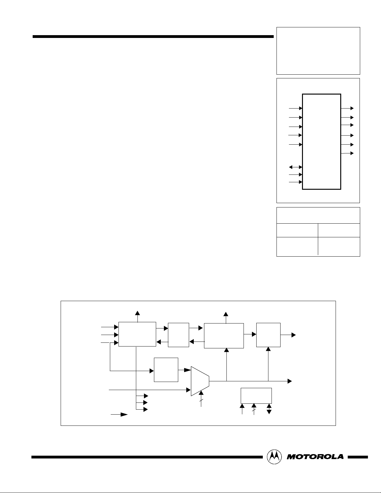
MC92300
DTVVIT
RESET_N
VC0,VC1[2:0]
VDCLK
SYMCLK
VTSTI[1:0]
BITCLK
VO
VLCK
VFF
VEF
SR[2:0]
• Operates at max. 50MBits/s output rate to work with all present DVB channels
• Implements K=7, (1718,1338) Viterbi decoder for rates 1/2, 2/3, 3/4, 5/6 and 7/8
with a survivor depth of 96
• Code rate and synchronization control programmable via I2C standard serial bus
• Automatic rate selection and signal quality output (qval)
• Full/empty flag generation of input FIFO for system monitoring of VDCLK/BITCLK
ratio
• Simplified system design with internal PLL for the generation of output BITCLK
from the incoming VDCLK for all depuncturing modes
• Available in a 128QFP package
VEF
Depuncturing
Viterbi
Core
VC1[2:0]
VC2[2:0]
VFF
Synchronizer
FIFO
VDCLK
SDA
DSA[6:0]
SCL
Ordering Information
Device
MC92300CG
VO
Package
128QFP
APLL
BIT-
SYMCLK
RESET_N
VLCK
SR
QVAL
2
VTSTI[1:0]
SCL
I2C
Interface
7
DSA
SDA
CLK
Figure 1. Viterbi Decoder Block Diagram
This document contains information on a new product.
Specifications and information herein are subject to change without notice.
MOTOROLA, INC. 1997 5/28/97
Page 2
Product Description
The Viterbi Decoder contains the Viterbi core logic,
which operates the K=7 convolutional code and generates
a lock indication after successful acquisition. The core
works with the main clock BITCLK, which provides the output data VO (output of the Viterbi). This clock is generated
by the integrated bit clock generator circuit and is adjusted
according to the programmed depuncturing rate.
The input to the chip are 3 bit soft decision data VC0/1
from the QPSK demodulator together with the associated
demodulator clock VDCLK. Rate adjustment in accordance
with the several depuncturing rates is achieved with the input FIFO. The data is read into the depuncturing logic with
the internally generated BITCLK.
Generator Polynomials
The Viterbi decoder is designed to decode bit streams
encoded using the DVB standard generator polynomials
(1718, 1338).
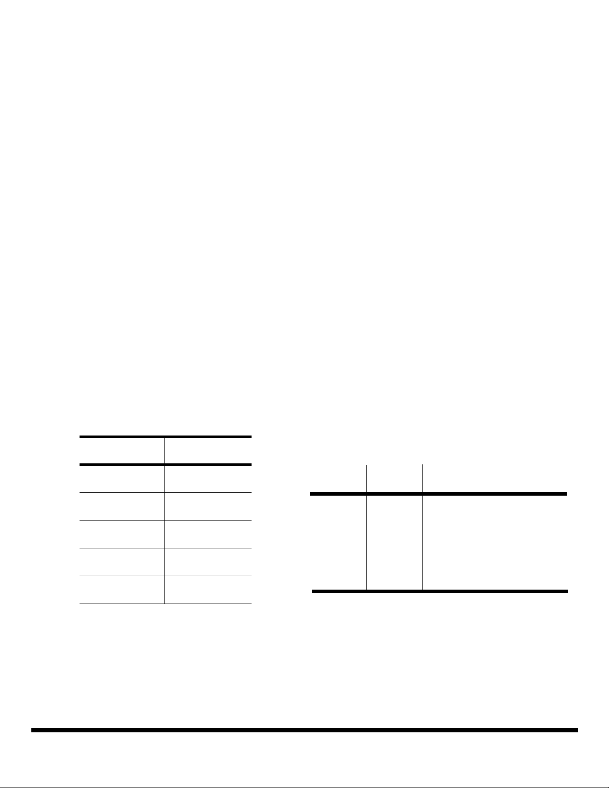
Punctured Codes
The Viterbi Decoder is able to decode a basic rate 1/2
convolutional code and the “standard” punctured codes for
a k=7 constraint length. The punctured codes are shown in
the table below. Specific bits of the original rate 1/2 code sequence are periodically deleted prior to transmission according to the entries in the table, where a 0 means that the
bit is deleted and a 1 means that the bit is transmitted.
Table 1 Deletion Map For Punctured Rate 1/2 Codes
Coding
Rate
Puncture
Map
The Viterbi block employs a method known as Syndrom
Based Node Synchronization to achieve both I & Q symbol
and punctured rate synchronization.
The theory of the Syndrom Based Node Synchronization is
based on the observation that the product of the incoming
data and a syndrom is zero if there are no errors If errors are
present in the data, the probability of 0’s and 1’s in the product increases.
The possible states that the synchronizer has to deal with
are a combination of the following factors:
1.The phasing of the received symbols.
I & Q input streams can either be processed as-is or
can be rotated 90oto account for constellation
rotation in the receiver.
2. Determination of the framing of the I and Q bit
streams so as to extract the correct symbol. There
are four possible ways to frame the two bit stream
and the synchronizer must determine the correct
one.
I2C Interface
The internal registers of the VITERBI are accessible
via the I2C interface. After reset, default values are preprogrammed, so that no more configuration is necessary.
APLL
In order to allow a simple system design, a Analogue
PLL is integrated for generation of the output Bit Clock. The
following output frequencies Ro are generated for a given
DVB transponder Bandwidth TBW respectively for a given
input symbol rate Rs.
1/2
2/3
3/4
1
1
11
10
110
101
TBW[MHz] Rs[MHz] Ro[MHz] for rates
1/2 2/3 3/4 5/6 7/8
36 38.3 28.3 37.7 42.4 47.2 49.5
33
30
27
5/6
7/8
11010
10101
1111010
1000101
26 20.5 20.5 27.3 30.7 34.2 35.9
Rs/R
o
1 4/3 3/2 5/3 7/4
Application
Synchronization
The MC92300 is used in satellite receiver implementa-
Prior to outputting valid data the Viterbi decoder block
must synchronize to the input data stream, i.e. remove any
phase ambiguity in the received symbols and determine the
punctured code rate transmitted
MOTOROLA MC92300
2 Rev.1.3
tion for DVB.
Packaging
The MC92300 is available in a 128-pin Plastic Quad
Flat Pack (128QFP) package.
Page 3

Viterbi Decoder Pin Description
P
O
E
V
N
V
S
I
S
S
D
S
R
E
S
V
V
E
T
T
R
T
S
S
E
_
T
T
S
A
V
I
I
E
S
T
[
[
T
Y
S
0
1
_
N
T
]
]
N
C
O
O
O
V
V
V
V
S
S
D
D
S
S
D
D
O
V
D
D
T
E
S
T
T
E
_
S
O
M
T
V
V
V
O
_
S
S
D
D
S
S
S
D
E
E
O
V
V
D
D
D
D
VDD
OVDD
VC1[2
OVSS
VC1[1]
OVSS
VC1[0]
OVSS
SYMCLK
OVSS
VSS
VDD
OVDD
VC0[2]
OVSS
VC0[1]
OVSS
VC0[0
OVSS
OVSS
VSS
VDD
OVDD
VDCLK
OVSS
VDCLK_DIV2
OVSS
VSS
TESTSEL
FREF
TESTOUT
VSS
]
128QFP
]
V
D
S
S
V
V
O
D
C
D
C
D
V
S
L
A
O
D
D
C
T
L
A
D
[
0
]
O
V
O
S
S
V
A
S
S
[
S
1
]
D
D
D
D
V
S
S
S
D
D
A
A
A
D
[
[
[
4
3
2
]
]
]
V
D
O
O
D
S
A
[
5
]
V
S
S
V
V
D
S
A
S
D
D
[
S
6
]
D
O
V
V
S
S
S
S
OVSS
OVDD
VDD
VSS
OVSS
BITCLK
OVDD
OVSS
VLCK
OVSS
VO
OVDD
VDD
VSS
OVSS
VFF
OVDD
VEF
OVSS
SR[2]
SR[1]
SR[0]
OVDD
VDD
SYMCLK - System Clock (input clock) VTSTI[1:0] - Test pins
BITCLK - System Clock (output clock) VTSTO - Test output
VDCLK - Input Clock RESET_ASYNC - Teset for Scan Test
VDCLK_DIV2 - VDCLK/2 TEST_SE - Test pin for Scan Mode
RESET_N - Asynchronous Reset TEST_MODE - Test pin for Scan Mode
VLCK - Viterbi Decoder in Lock
VFF - FIFO Full Flag MOTOROLA Device Test Pins:
VEF - FIFO Empty Flag 51, 56-62, 105, 110-115, 120
SR[2:0] - Selected Rate (don’t connect these pins)
VO - Viterbi Decoder Output
VC0,VC1[2:0] - Soft Decision Input NOT CONNECTED Pins:
SDA - Data Bus of I2C-interface 27, 33, 34, 88-94, 99-102
DSA[6:0] - Slave Address of I2C-interface
SCL - Clock Line of I2C-interface
TESTSEL,
FREF,
TESTOUT,
VCOCTL - APLL pins
MC92300 MOTOROLA
Rev.1.3 3
Page 4

Motorola reserves the right to make changes without further notice to any products herein. Motorola makes no warranty, representation or guarantee regarding the
suitability of its products for any particular purpose, nor does Motorola assume any liability arising out of the application or use of any product or circuit, and
specifically disclaims any and all liability, including without limitation consequential or incidental damages. “Typical” parameters which may be provided in Motorola
data sheets and/or specifications can and do vary in different applications and actual performance may vary over time. All operating parameters, including
“Typicals” must be validated for each customer application by customer’s technical experts. Motorola does not convey any license under its patent rights nor the
rights of others. Motorola products are not designed, intended, or authorized for use as components in systems intended for surgical implant into the body, or other
applications intended to support or sustain life, or for any other application in which the failure of the Motorola product could create a situation where personal injury
or death may occur. Should Buyer purchase or use Motorola products for any such unintended or unauthorized application, Buyer shall indemnify and hold
Motorola and its officers, employees, subsidiaries, affiliates, and distributors harmless against all claims, costs, damages, and expenses, and reasonable attorney
fees arising out of directly or indirectly, any claim of personal injury or death associated with such unintended or unauthorized use, even if such claim alleges that
Motorola was negligent regarding the design or manufacture of the part. Motorola and are registered trademarks of Motorola, Inc. Motorola, Inc. is an Equal
Opportunity/Affirmative Action Employer.
How to reach us:
USA/EUROPE/Locations Not Listed: Motorola Literature Distribution; JAPAN: Nippon Motorola Ltd.; Tatsumi-SPD-JLDC, 6F Seibu-Butsuryu-Center,
P.O. Box 5405, Denver Colorado 80217. 1-800-441-2447 or 303-675-2140 3-14-2 Tatsumi Koto-Ku, Tokyo 135, Japan. 81-3-3521-8315
TM
: RMFAX0@email.sps.mot.com -TOUCHTONE (602) 244-6609 ASIA/PACIFIC: Motorola Semiconductors H.K. Ltd.; 8B T ai Ping Industial P ark,
MFax
INTERNET:http://mot-sps.com/sps/General/sales.html 51 Ting Kok Road, Tai Po, N.T., Hong Kong. 852-26629298
MC92300
 Loading...