

Page 1
SEMICONDUCTOR TECHNICAL DATA
!' !% &
"&% %
% !# % "&%$
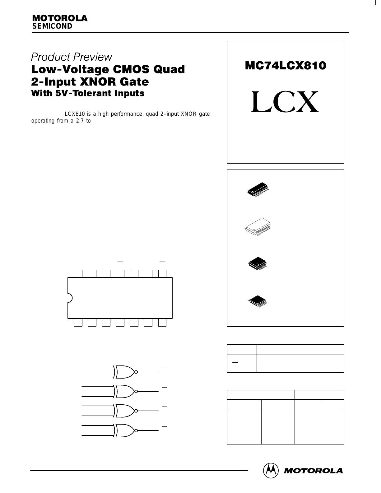
The MC74LCX810 is a high performance, quad 2–input XNOR gate
operating from a 2.7 to 3.6V supply. High impedance TTL compatible
inputs significantly reduce current loading to input drivers while TTL
compatible outputs offer improved switching noise performance. A V
specification of 5.5V allows MC74LCX810 inputs to be safely driven from
5V devices.
Current drive capability is 24mA at the outputs.
I
LOW–VOLTAGE CMOS
QUAD 2–INPUT XNOR GATE
• Designed for 2.7 to 3.6V V
Operation
CC
• 5V Tolerant Inputs — Interface Capability With 5V TTL Logic
• LVTTL Compatible
• LVCMOS Compatible
• 24mA Balanced Output Sink and Source Capability
• Near Zero Static Supply Current (10µA) Substantially Reduces System
Power Requirements
• Latchup Performance Exceeds 500mA
• ESD Performance: Human Body Model >2000V; Machine Model >200V
Pinout: 14–Lead (Top View)
VCCA2 B2 O2
1314 12 11 10 9 8
21 34567
A0 B0 O0 A1 B1 O1 GND
LOGIC DIAGRAM
1
A0
2
B0
4
A1
5
B1
13
A2
12
B2
10
A3
9
B3
A3 B3 O3
3
6
11
8
O0
O1
O2
O3
14
1
14
1
14
1
14
1
PIN NAMES
Pins
An, Bn
On
Function
Data Inputs
Outputs
FUNCTION TABLE
Inputs Outputs
An Bn
L
L
H
H
D SUFFIX
PLASTIC SOIC
CASE 751A–03
M SUFFIX
PLASTIC SOIC EIAJ
CASE 965–01
SD SUFFIX
PLASTIC SSOP
CASE 940A–03
DT SUFFIX
PLASTIC TSSOP
CASE 948G–01
L
H
L
H
On
H
L
L
H
This document contains information on a product under development. Motorola reserves the
right to change or discontinue this product without notice.
11/96
Motorola, Inc. 1996
1
REV 0
Page 2
MC74LCX810
L
0.076 (0.003)
SEATING
–T–
PLANE
L/2
PIN 1
IDENT
14 8
0.20 (0.008) T
C
D
G
K14X REF
0.12 (0.005) V
71
A
–V–
M
S
U
H
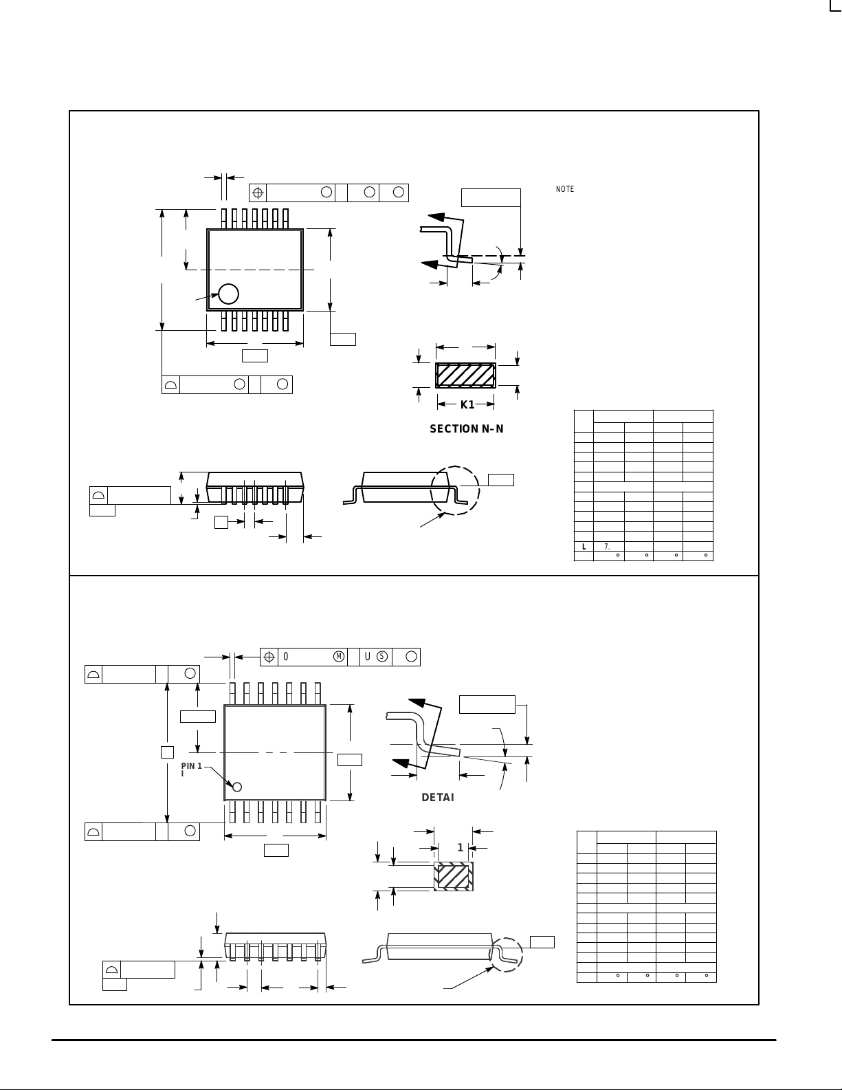
OUTLINE DIMENSIONS
SD SUFFIX
PLASTIC SSOP PACKAGE
CASE 940A–03
ISSUE B
B
T
–U–
S
U
DETAIL E
S
N
N
DETAIL E
J
SECTION N–N
M
0.25 (0.010)
M
F
K
K1
–W–
J1
NOTES:
1 DIMENSIONING AND TOLERANCING PER ANSI
Y14.5M, 1982.
2 CONTROLLING DIMENSION: MILLIMETER.
3 DIMENSION A DOES NOT INCLUDE MOLD FLASH,
PROTRUSIONS OR GATE BURRS. MOLD FLASH
OR GATE BURRS SHALL NOT EXCEED 0.15
(0.006) PER SIDE.
4 DIMENSION B DOES NOT INCLUDE INTERLEAD
FLASH OR PROTRUSION. INTERLEAD FLASH OR
PROTRUSION SHALL NOT EXCEED 0.15 (0.006)
PER SIDE.
5 DIMENSION K DOES NOT INCLUDE DAMBAR
PROTRUSION/INTRUSION. ALLOWABLE DAMBAR
PROTRUSION SHALL BE 0.13 (0.005) TOTAL IN
EXCESS OF K DIMENSION AT MAXIMUM
MATERIAL CONDITION. DAMBAR INTRUSION
SHALL NOT REDUCE DIMENSION K BY MORE
THAN 0.07 (0.002) AT LEAST MATERIAL
CONDITION.
6 TERMINAL NUMBERS ARE SHOWN FOR
REFERENCE ONLY.
7 DIMENSION A AND B ARE TO BE DETERMINED
AT DATUM PLANE –W–.
MILLIMETERS
DIMAMIN MAX MIN MAX
6.07 6.33 0.238 0.249
B 5.20 5.38 0.205 0.212
C 1.73 1.99 0.068 0.078
D 0.05 0.21 0.002 0.008
F 0.63 0.95 0.024 0.037
G 0.65 BSC 0.026 BSC
H 1.08 1.22 0.042 0.048
J 0.09 0.20 0.003 0.008
J1 0.09 0.16 0.003 0.006
K 0.25 0.38 0.010 0.015
K1 0.25 0.33 0.010 0.013
L 7.65 7.90 0.301 0.311
M 0 8 0 8
____
INCHES
0.10 (0.004)
SEATING
–T–
PLANE
PLASTIC TSSOP PACKAGE
DT SUFFIX
CASE 948G–01
ISSUE O
S
U
T
S
N
0.25 (0.010)
U0.15 (0.006) T
S
2X L/2
14X REFK
0.10 (0.004) V
14
M
8
M
L
PIN 1
IDENT.
1
S
U0.15 (0.006) T
A
–V–
B
–U–
N
F
7
DETAIL E
K
K1
J
J1
SECTION N–N
C
D
G
H
DETAIL E
NOTES:
1 DIMENSIONING AND TOLERANCING PER ANSI
Y14.5M, 1982.
2 CONTROLLING DIMENSION: MILLIMETER.
3 DIMENSION A DOES NOT INCLUDE MOLD FLASH,
PROTRUSIONS OR GATE BURRS. MOLD FLASH
OR GATE BURRS SHALL NOT EXCEED 0.15
(0.006) PER SIDE.
4 DIMENSION B DOES NOT INCLUDE INTERLEAD
FLASH OR PROTRUSION. INTERLEAD FLASH OR
PROTRUSION SHALL NOT EXCEED
0.25 (0.010) PER SIDE.
5 DIMENSION K DOES NOT INCLUDE DAMBAR
PROTRUSION. ALLOWABLE DAMBAR
PROTRUSION SHALL BE 0.08 (0.003) TOTAL IN
EXCESS OF THE K DIMENSION AT MAXIMUM
MATERIAL CONDITION.
6 TERMINAL NUMBERS ARE SHOWN FOR
REFERENCE ONLY.
7 DIMENSION A AND B ARE TO BE DETERMINED
AT DATUM PLANE –W–.
INCHESMILLIMETERS
–W–
DIM MIN MAX MIN MAX
A 4.90 5.10 0.193 0.200
B 4.30 4.50 0.169 0.177
C ––– 1.20 ––– 0.047
D 0.05 0.15 0.002 0.006
F 0.50 0.75 0.020 0.030
G 0.65 BSC 0.026 BSC
H 0.50 0.60 0.020 0.024
J 0.09 0.20 0.004 0.008
J1 0.09 0.16 0.004 0.006
K 0.19 0.30 0.007 0.012
K1 0.19 0.25 0.007 0.010
L 6.40 BSC 0.252 BSC
M 0 8 0 8
____
MOTOROLA LCX DATA
2
BR1339 — REV 3
Page 3

OUTLINE DIMENSIONS
MC74LCX810
1
SEATING
PLANE
14 8
1
Z
e
b
0.13 (0.005)
–A
–
G
D 14 PL
0.25 (0.010) T B A
7
D
M
0.10 (0.004)
814
–B–P 7 PL
7
M
HEE
A
A
1
C
K
S S
VIEW P
D SUFFIX
PLASTIC SOIC PACKAGE
CASE 751A–03
ISSUE F
M M
B0.25 (0.010)
X 45°
R
M
M SUFFIX
PLASTIC SOIC EIAJ PACKAGE
CASE 965–01
ISSUE O
L
E
Q
1
_
M
L
DETAIL P
c
NOTES:
1. DIMENSIONING AND TOLERANCING PER ANSI
Y14.5M, 1982.
2. CONTROLLING DIMENSION: MILLIMETER.
3. DIMENSIONS A AND B DO NOT INCLUDE
MOLD PROTRUSION.
4. MAXIMUM MOLD PROTRUSION 0.15 (0.006)
PER SIDE.
5. DIMENSION D DOES NOT INCLUDE DAMBAR
PROTRUSION. ALLOWABLE DAMBAR
PROTRUSION SHALL BE 0.127 (0.005) TOTAL
IN EXCESS OF THE D DIMENSION AT
MAXIMUM MATERIAL CONDITION.
F
J
NOTES:
1 DIMENSIONING AND TOLERANCING PER ANSI
Y14.5M, 1982.
2 CONTROLLING DIMENSION: MILLIMETER.
3 DIMENSIONS D AND E DO NOT INCLUDE MOLD
FLASH OR PROTRUSIONS AND ARE MEASURED
AT THE PARTING LINE. MOLD FLASH OR
PROTRUSIONS SHALL NOT EXCEED 0.15 (0.006)
PER SIDE.
4 TERMINAL NUMBERS ARE SHOWN FOR
REFERENCE ONLY.
5 THE LEAD WIDTH DIMENSION (b) DOES NOT
INCLUDE DAMBAR PROTRUSION. ALLOWABLE
DAMBAR PROTRUSION SHALL BE 0.08 (0.003)
TOTAL IN EXCESS OF THE LEAD WIDTH
DIMENSION AT MAXIMUM MATERIAL CONDITION.
DAMBAR CANNOT BE LOCATED ON THE LOWER
RADIUS OR THE FOOT. MINIMUM SPACE
BETWEEN PROTRUSIONS AND ADJACENT LEAD
TO BE 0.46 ( 0.018).
MILLIMETERS INCHES
MIN MINMAX MAX
DIM
A
8.55
B
3.80
C
1.35
D
0.35
F
0.40
1.27 BSC 0.050 BSC
G
J
0.19
K
0.10
M
0
°
P
5.80
R
0.25
MILLIMETERS
DIM MIN MAX MIN MAX
A
--- 2.05 --- 0.081
A
0.05 0.20 0.002 0.008
1
b
0.35 0.50 0.014 0.020
c
0.18 0.27 0.007 0.011
D
9.90 10.50 0.390 0.413
E
5.10 5.45 0.201 0.215
e
1.27 BSC 0.050 BSC
H
7.40 8.20 0.291 0.323
E
L
0.50 0.85 0.020 0.033
L
1.10 1.50 0.043 0.059
E
M
Q
1
Z
10
0
_
0.70 0.90 0.028 0.035
--- 1.42 --- 0.056
0.337
8.75
0.150
4.00
0.054
1.75
0.014
0.49
0.016
1.25
0.008
0.25
0.004
0.25
0
°
7
°
0.228
6.20
0.010
0.50
INCHES
10
0
_
_
_
0.344
0.157
0.068
0.019
0.049
0.009
0.009
7
°
0.244
0.019
LCX DATA
BR1339 — REV 3
3 MOTOROLA
Page 4

MC74LCX810
Motorola reserves the right to make changes without further notice to any products herein. Motorola makes no warranty , representation or guarantee regarding
the suitability of its products for any particular purpose, nor does Motorola assume any liability arising out of the application or use of any product or circuit, and
specifically disclaims any and all liability, including without limitation consequential or incidental damages. “T ypical” parameters which may be provided in Motorola
data sheets and/or specifications can and do vary in different applications and actual performance may vary over time. All operating parameters, including “Typicals”
must be validated for each customer application by customer’s technical experts. Motorola does not convey any license under its patent rights nor the rights of
others. Motorola products are not designed, intended, or authorized for use as components in systems intended for surgical implant into the body, or other
applications intended to support or sustain life, or for any other application in which the failure of the Motorola product could create a situation where personal injury
or death may occur. Should Buyer purchase or use Motorola products for any such unintended or unauthorized application, Buyer shall indemnify and hold Motorola
and its officers, employees, subsidiaries, affiliates, and distributors harmless against all claims, costs, damages, and expenses, and reasonable attorney fees
arising out of, directly or indirectly, any claim of personal injury or death associated with such unintended or unauthorized use, even if such claim alleges that
Motorola was negligent regarding the design or manufacture of the part. Motorola and are registered trademarks of Motorola, Inc. Motorola, Inc. is an Equal
Opportunity/Affirmative Action Employer.
How to reach us:
USA/EUROPE/Locations Not Listed: Motorola Literature Distribution; JAPAN: Nippon Motorola Ltd.; Tatsumi–SPD–JLDC, 6F Seibu–Butsuryu–Center,
P.O. Box 5405, Denver, Colorado 80217. 1–800–441–2447 3–14–2 Tatsumi Koto–Ku, Tokyo 135, Japan. 03–81–3521–8315
Mfax: RMFAX0@email.sps.mot.com – TOUCHT ONE 602–244–6609 ASIA/PACIFIC: Motorola Semiconductors H.K. Ltd.; 8B Tai Ping Industrial Park,
INTERNET: http://Design–NET .com 51 Ting Kok Road, Tai Po, N.T., Hong Kong. 852–26629298
MOTOROLA LCX DATA
4
◊
MC74LCX810/D
BR1339 — REV 3
 Loading...