

Page 1
4-261
FAST AND LS TTL DATA
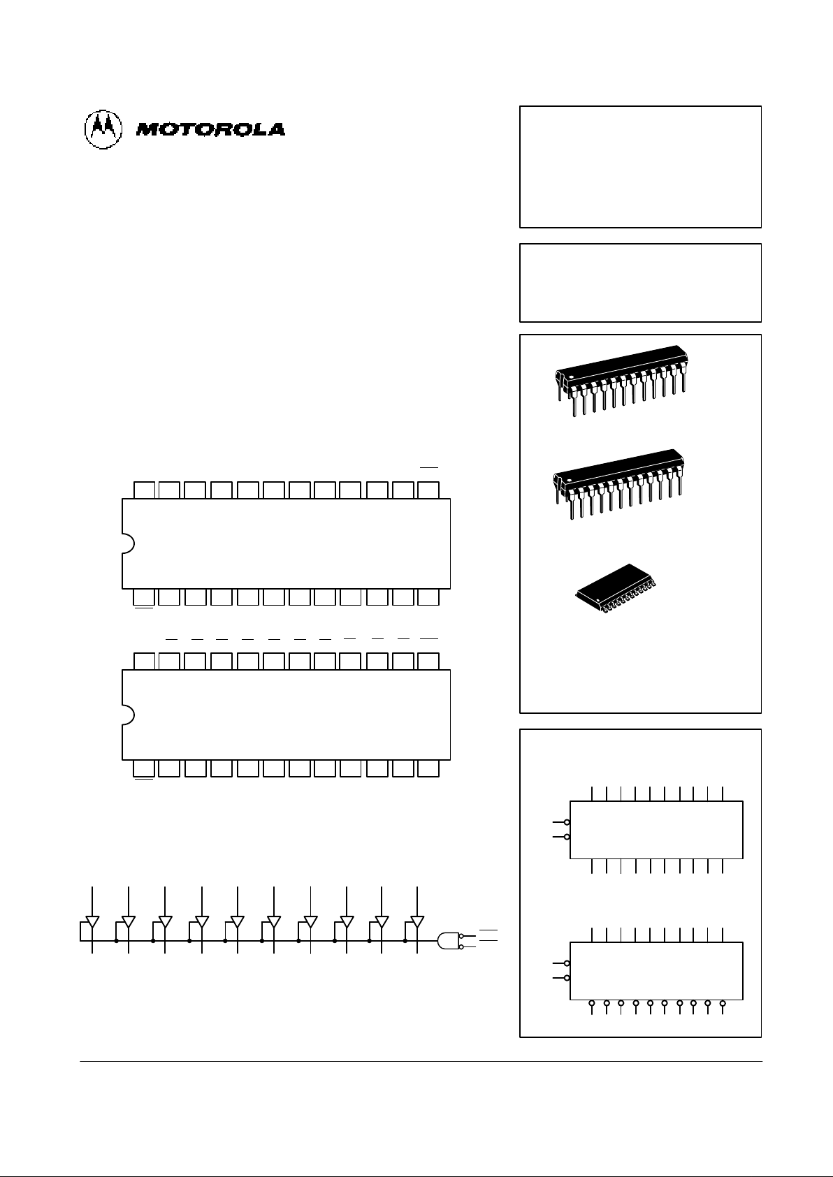
10-BIT BUFFERS/LINE DRIVERS
(WITH 3-STATE OUTPUTS)
The MC54/74F827 and MC54/74F828 10-bit bus buffers provide high performance bus interface buffering for wide data/address paths or buses carrying parity. The 10-bit buffers have NOR output enables for maximum control
flexibility.
The F827 and F828 are functionally and pin compatible to AMD’s 29827
and 29828. The F828 is an inverting version of the F827.
• 3-State Outputs Drive Memory Address, Bus and Clock Lines
• Outputs Sink 64 mA
• 15 mA Source Current
• Flow Through Pinout Architecture for Microprocessor Oriented
Applications
CONNECTION DIAGRAMS (TOP VIEW)
22 21 20 19 18 17
1 2 3 4 5 6
7
24 23
8
V
CC
OE
1
O0O1O2O
3
O
5
O
4
O
6
D0D1D2D3D4D5D
6
9 10
11
12
D7D8D9GND
16 15 14 13
O
7
O
9
O
8
OE
2
22 21 20 19 18 17
1 2 3 4 5 6
7
24 23
8
V
CC
OE
1
O0O1O2O
3
O
5
O
4
O
6
D0D1D2D3D4D5D
6
9 10
11
12
D7D8D9GND
16 15 14 13
O
7
O
9
O
8
OE
2
F827
F828
LOGIC DIAGRAM
D
9
O
9
D
8
O
8
D
7
O
7
D
6
O
6
D
5
O
5
D
4
O
4
D
3
O
3
D
2
O
2
D
1
O
1
D
0
O
0
OE
1
OE
2
Please note that this diagram is provided only for the understanding of logic operations and should
not be used to estimate propagation delays.
MC54/74F827
MC54/74F828
10-BIT BUFFERS/LINE DRIVERS
(WITH 3-STATE OUTPUTS)
FAST SCHOTTKY TTL
ORDERING INFORMATION
MC54FXXXJ Ceramic
MC74FXXXN Plastic
MC74FXXXDW SOIC
N SUFFIX
PLASTIC
CASE 724-03
DW SUFFIX
SOIC
CASE 751E-03
24
1
24
1
J SUFFIX
CERAMIC
CASE 758-01
24
1
LOGIC SYMBOL
OE
1
OE
2
D0D1D2D3D4D5D6D7D8D
9
O
0
O1O2O3O4O5O6O7O8O
9
F827
2 3 4 5 6 7 8 9 10 11
1
13
23 22 21 20 19 18 17 16 15 14
OE
1
OE
2
D0D1D2D3D4D5D6D7D8D
9
O
0
O1O2O3O4O5O6O7O8O
9
F828
2 3 4 5 6 7 8 9 10 11
1
13
23 22 21 20 19 18 17 16 15 14
Page 2
4-262
FAST AND LS TTL DATA
MC54/74F827 • MC54/74F828
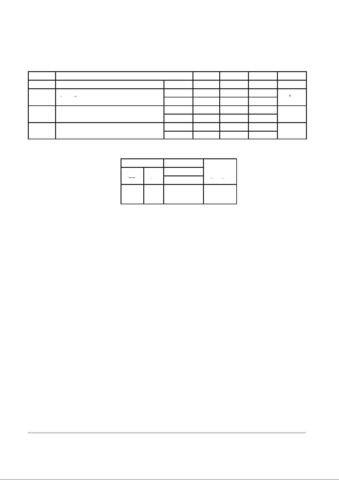
GUARANTEED OPERATING RANGES
Symbol Parameter Min Typ Max Unit
V
CC
Supply Voltage* 54, 74 4.5 5.0 5.5 V
Operating Ambient
54 –55 25 125
T
A
Operating Ambient
Temperature Range
74 0 25 70
°C
54 — — –12
IOHOutput Current — High
74 — — –15
mA
54 — — 48
IOLOutput Current — Low
74 — — 64
mA
FUNCTION TABLE
Inputs Outputs
O
n
OE
D
n
F827 F828
Function
L H H L Transparent
L L L H Transparent
H X Z Z High Z
H = HIGH Voltage Level
L = LOW Voltage Level
X = Don’t Care
Z = High Impedance
Page 3

4-263
FAST AND LS TTL DATA
MC54/74F827 • MC54/74F828
DC CHARACTERISTICS OVER OPERATING TEMPERATURE RANGE (unless otherwise specified)
Limits
Symbol
Parameter
Min Typ Max
Unit
Test Conditions
V
IH
Input HIGH Voltage 2.0 — — V Guaranteed Input HIGH Voltage
V
IL
Input LOW Voltage — — 0.8 V Guaranteed Input LOW Voltage
V
IK
Input Clamp Diode Voltage — — –1.2 V IIN = –18 mA VCC = MIN
54 2.0 — — V IOH = –12 mA
74 2.0 — — V IOH = –15 mA
VCC = MIN
VOHOutput HIGH Voltage
54, 74 2.4 — — V IOH = –3.0 mA
CC
= MIN
74 2.7 — — V IOH = –3.0 mA VCC = 4.75 V
54 — — 0.55 V IOL = 48 mA
VOLOutput LOW Voltage
74 — — 0.55 V IOL = 64 mA
VCC = MIN
I
OZH
Output Off Current HIGH — — 50 µA V
OUT
= 2.7 V VCC = MAX
I
OZL
Output Off Current LOW — — –50 µA V
OUT
= 0.5 V VCC = MAX
— — 20 µA VIN = 2.7 V
IIHInput HIGH Current
— — 100 µA VIN = 7.0 V
VCC = 0 V
I
IL
Input LOW Current — — –20 µA VIN = 0.5 V VCC = MAX
I
OS
Output Short Circuit Current (Note 2) –100 — –225 mA V
OUT
= 0 V VCC = MAX
Power Supply Current
F827 — — 70 mA
I
CCH
Power Supply Current
HIGH
F828 — — 45 mA
Outputs HIGH
VCC = MAX
Power Supply Current
F827 — — 100 mA
I
CCL
Power Supply Current
LOW
F828 — — 85 mA
Outputs LOW
VCC = MAX
F827 — — 90 mA
I
CCZ
Power Supply Current OFF
F828 — — 70 mA
Outputs OFF
VCC = MAX
NOTES:
1. For conditions shown as MIN or MAX, use the appropriate value specified under recommended operating conditions for the applicable device type.
2. Not more than one output should be shorted at a time, nor for more than 1 second.
AC CHARACTERISTICS
54/74F 54F 74F
TA = +25°C
VCC = +5.0 V
TA = – 55°C to +125°C
VCC = 5.0 V ± 10%
TA = 0°C to 70°C
VCC = 5.0 V ± 10%
VCC = +5.0 V
CL = 50 pF
VCC = 5.0 V ± 10%
CL = 50 pF
VCC = 5.0 V ± 10%
CL = 50 pF
Symbol
Parameter
Min Max Min Max Min Max
Unit
t
Propagation Delay,
2.0 8.5 2.0 10 2.0 9.0
t
PLH
t
PHL
Propagation Delay,
Data to Output
2.0 8.5 2.0 10 2.0 9.0
ns
t
3.5 9.5 3.5 11 3.5 10
t
PZH
t
PZL
Output Enable Time
F827
4.0 9.0 4.0 10.5 4.0 9.5
ns
t
2.0 8.0 2.0 9.5 2.0 8.5
t
PHZ
t
PLZ
Output Disable Time
1.5 8.0 1.5 9.5 1.5 8.5
ns
t
Propagation Delay,
2.0 9.0 2.0 11 2.0 10
t
PLH
t
PHL
Propagation Delay,
Data to Output
1.0 8.0 1.0 10 1.0 9.0
ns
t
3.5 9.5 3.5 11 3.5 10
t
PZH
t
PZL
Output Enable Time
F828
4.0 9.0 4.0 10.5 4.0 9.5
ns
t
2.0 8.5 2.0 10 2.0 9.0
t
PHZ
t
PLZ
Output Disable Time
1.5 7.0 1.5 9.0 1.5 8.0
ns
 Loading...