

Page 1
MC145149MOTOROLA
1
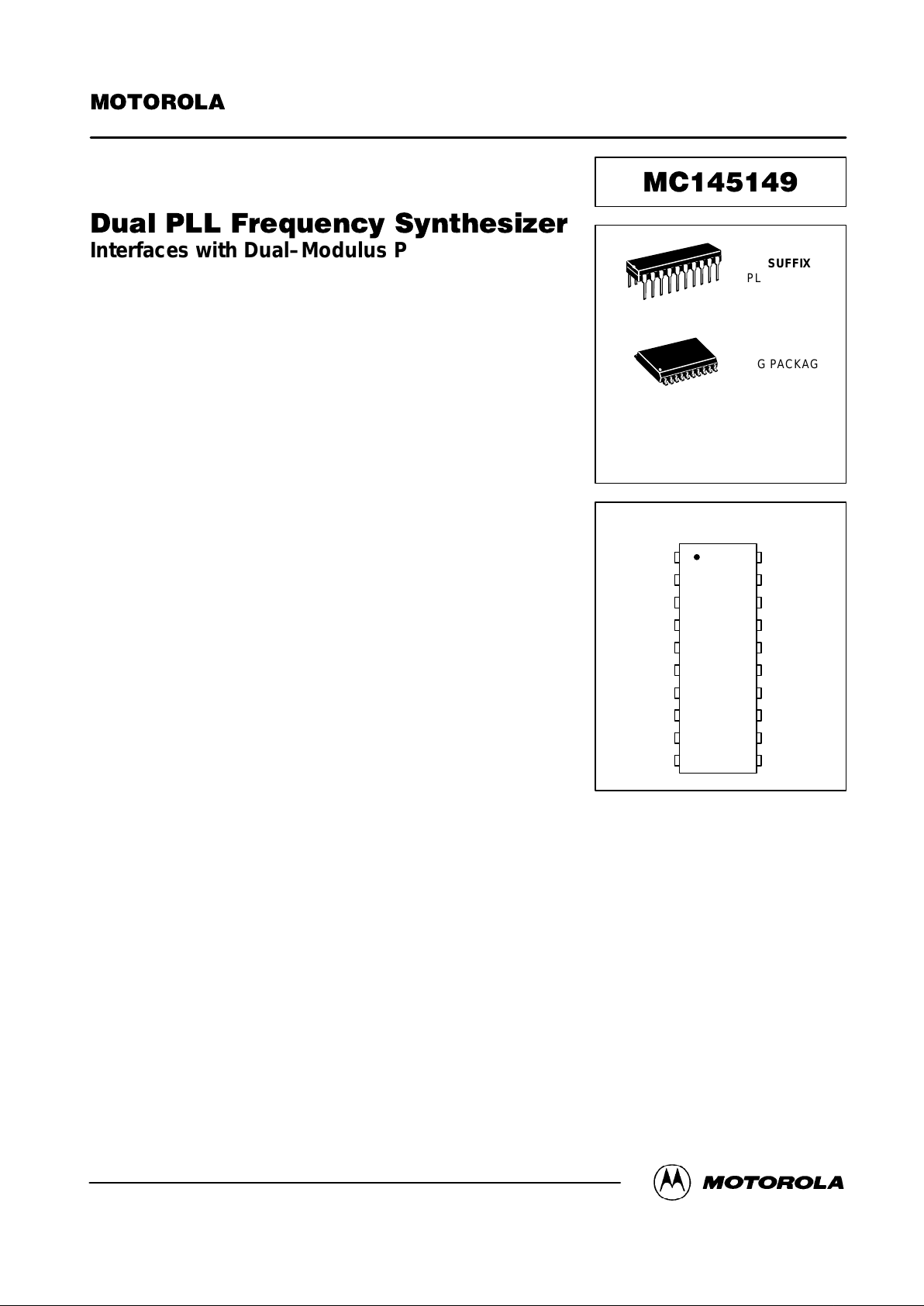
Interfaces with Dual–Modulus Prescalers
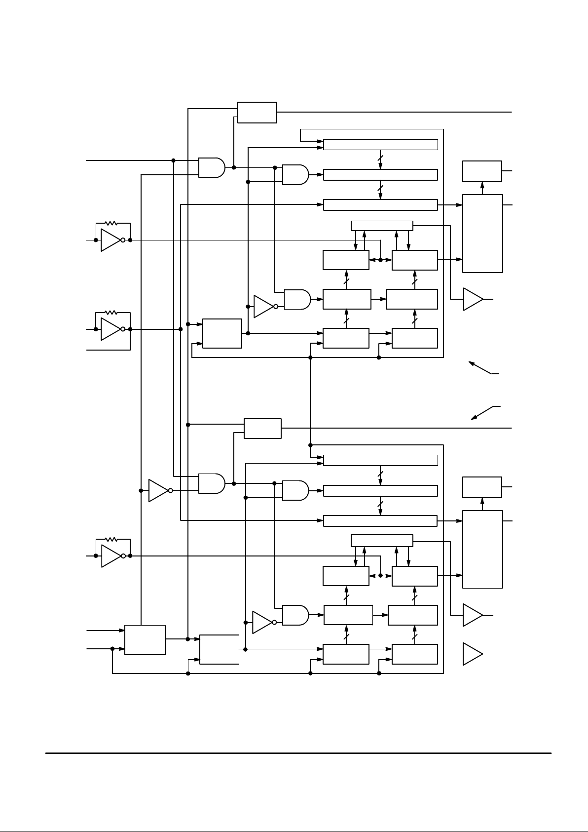
The MC145149 contains two PLL Frequency Synthesizers which share a
common serial data port and common reference oscillator. The device
contains two 14–stage R counters, two 10–stage N counters, and two
7–stage A counters. All six counters are fully programmable through a serial
port. The divide ratios are latched into the appropriate counter latch
according to the last data bits (control bits) entered.
When combined with external low–pass filters and voltage controlled
oscillators (VCOs), the MC145149 can provide all the remaining functions
for two PLL frequency synthesizers operating up to the device’s frequency
limit. For higher VCO frequency operation, a down mixer or dual–modulus
prescaler can be used between the VCO and the synthesizer IC.
• Low Power Consumption Through Use of CMOS Technology
• Wide Operating Voltage Range: 3 to 9 V
• Operating Temperature Range: – 40 to + 85°C
•÷ R Range = 3 to 16,383
•÷ N Range = 3 to 1023
•÷ A Range = 0 to 127
• Two “Linearized” Three–State Digital Phase Detectors with No Dead Zone
• Two Lock Detect Signals (LD1 and LD2)
• Two Open–Drain Port Expander Outputs (SW1 and SW2)
• Compatible with the Serial Peripheral Interface (SPI) on CMOS MCUs
Order this document
by MC145149/D
SEMICONDUCTOR TECHNICAL DATA
P SUFFIX
PLASTIC DIP
CASE 738
DW SUFFIX
SOG PACKAGE
CASE 751D
ORDERING INFORMATION
MC145149P Plastic DIP
MC145149DW SOG Package
20
1
20
1
CLK
f
in1
ENB
MC1
LD1
LD2
MC2
S/R
out
f
in2
DATA 5
4
3
2
1
10
9
8
7
6
14
15
16
17
18
19
20
11
12
13
OSC
out
SW1
V
DD1
PD
out1
V
SS1
V
SS2
PD
out2
V
DD2
SW2
OSC
in
PIN ASSIGNMENT
Motorola, Inc. 1995
Page 2
MC145149 MOTOROLA
2
CLK
DATA
6
5
PLL2
PLL1
SW1
17
SW2
14
10
10
7
7
14
14
10
10
7
7
14
14
8
2–BIT
CONTROL
S/R
7
10–BIT S/R7–BIT S/R
÷
A COUNTER
LATCH
10–BIT ÷ N
COUNTER
7–BIT ÷ A
COUNTER
MODULUS
CONTROL 2
(MC2)
9
12
10
LOCK
DETECT
14–BIT
÷
R COUNTER
1–BIT
LATCH
1–BIT
CONTROL
S/R
REFERENCE COUNTER LATCH
CONTROL LOGIC
PHASE
DETECTOR
÷
N COUNTER
LATCH
14–BIT SHIFT REGISTER
16
15
4
ENB
3
10–BIT S/R7–BIT S/R
÷
A COUNTER
LATCH
10–BIT
÷
N
COUNTER
7–BIT ÷ A
COUNTER
MODULUS
CONTROL 1
(MC1)
2
19
1
LOCK
DETECT
14–BIT
÷
R COUNTER
1–BIT
LATCH
1–BIT
CONTROL
S/R
REFERENCE COUNTER LATCH
CONTROL LOGIC
PHASE
DETECTOR
÷
N COUNTER
LATCH
14–BIT SHIFT REGISTER
OSC
in
OSC
out
f
in1
f
in2
S/R
out
PD
out2
f
R
PIN 13
=
V
DD2
PIN 11
=
V
SS2
PD
out1
f
R
PIN 18
=
V
DD1
PIN 20
=
V
SS1
BLOCK DIAGRAM
f
V
f
V
LD2
LD1
Page 3
MC145149MOTOROLA
3
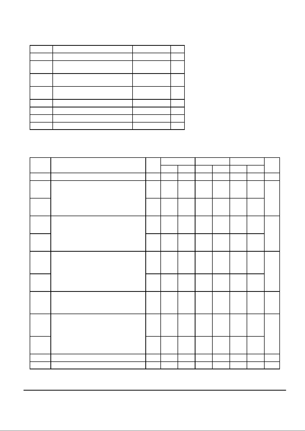
MAXIMUM RATINGS* (Voltages Referenced to V
SS
)
Symbol Rating Value Unit
V
DD
DC Supply Voltage – 0.5 to + 10 V
Vin, V
out
Input or Output Voltage (DC or T ransient)
except SW1, SW2
– 0.5 to VDD + 0.5 V
V
out
Output Voltage (DC or Transient) — SW1,
SW2
– 0.5 to 15 V
Iin, I
out
Input or Output Current (DC or Transient),
per Pin
± 10 mA
IDD, I
SS
Supply Current, VDD or VSS Pins ± 30 mA
P
D
Power Dissipation, per Package† 500 mW
T
stg
Storage Temperature – 65 to + 150 °C
T
L
Lead T emperature (8–Second Soldering) 260 °C
*Maximum Ratings are those values beyond which damage to the device may occur.
†Power Dissipation Temperature Derating:
Plastic DIP: – 12 mW/°C from 65 to 85°C
SOG Package: – 7 mW/°C from 65 to 85°C
ELECTRICAL CHARACTERISTICS (Voltages Referenced to V
SS
)
V
– 40°C 25°C 85°C
Symbol Characteristic
V
DD
V
Min Max Min Max Min Max
Unit
V
DD
Power Supply Voltage Range — 3 9 3 9 3 9 V
V
OL
Output Voltage 0 Level
Vin = 0 V or V
DD
I
out
= 0 µA
3
5
9
—
—
—
0.05
0.05
0.05
—
—
—
0.05
0.05
0.05
—
—
—
0.05
0.05
0.05
V
V
OH
1 Level 3
5
9
2.95
4.95
8.95
—
—
—
2.95
4.95
8.95
—
—
—
2.95
4.95
8.95
—
—
—
V
IL
Input Voltage 0 Level
V
out
= 0.5 V or VDD – 0.5 V
(All Outputs Except OSC
out
)
3
5
9
—
—
—
0.9
1.5
2.7
—
—
—
0.9
1.5
2.7
—
—
—
0.9
1.5
2.7
V
V
IH
1 Level 3
5
9
2.1
3.5
6.3
—
—
—
2.1
3.5
6.3
—
—
—
2.1
3.5
6.3
—
—
—
I
OH
Output Current — MC1, MC2
V
out
= 2.7 V Source
V
out
= 4.6 V
V
out
= 8.5 V
3
5
9
– 0.60
– 0.90
– 1.50
—
—
—
– 0.50
– 0.75
– 1.25
—
—
—
– 0.30
– 0.50
– 0.80
—
—
—
mA
I
OL
V
out
= 0.3 V Sink
V
out
= 0.4 V
V
out
= 0.5 V
3
5
9
1.30
1.90
3.80
—
—
—
1.10
1.70
3.30
—
—
—
0.66
1.08
2.10
—
—
—
I
OL
Output Current — SW1, SW2
V
out
= 0.3 V Sink
V
out
= 0.4 V
V
out
= 0.5 V
3
5
9
0.80
1.50
3.50
—
—
—
0.48
0.90
2.10
—
—
—
0.24
0.45
1.50
—
—
—
mA
I
OH
Output Current — Other Outputs
V
out
= 2.7 V Source
V
out
= 4.6 V
V
out
= 8.5 V
3
5
9
– 0.44
– 0.64
– 1.30
—
—
—
– 0.35
– 0.51
– 1.00
—
—
—
– 0.22
– 0.36
– 0.70
—
—
—
mA
I
OL
V
out
= 0.3 V Sink
V
out
= 0.4 V
V
out
= 0.5 V
3
5
9
0.44
0.64
1.30
—
—
—
0.35
0.51
1.00
—
—
—
0.22
0.36
0.70
—
—
—
I
in
Input Current — DATA, CLK, ENB 9 — ± 0.3 — ± 0.1 — ± 1.0 µA
I
in
Input Current — fin, OSC
in
9 — ± 50 — ± 25 — ± 22 µA
(continued)
This device contains circuitry to protect
against damage due to high static voltages or
electric fields, however, it is advised that normal
precautions be taken to avoid applications of any
voltage higher than maximum rated voltages to
this high–impedance circuit. For proper operation, it is recommended that Vin and V
out
be
constrained to the range VSS≤ (Vin or
V
out
) ≤ VDD except SW1 and SW2 which may
range up to 15 V.
Unused inputs must always be tied to an
appropriate logic voltage level (e.g., either V
SS
or VDD). Unused outputs should be left floating.
Page 4
MC145149 MOTOROLA
4
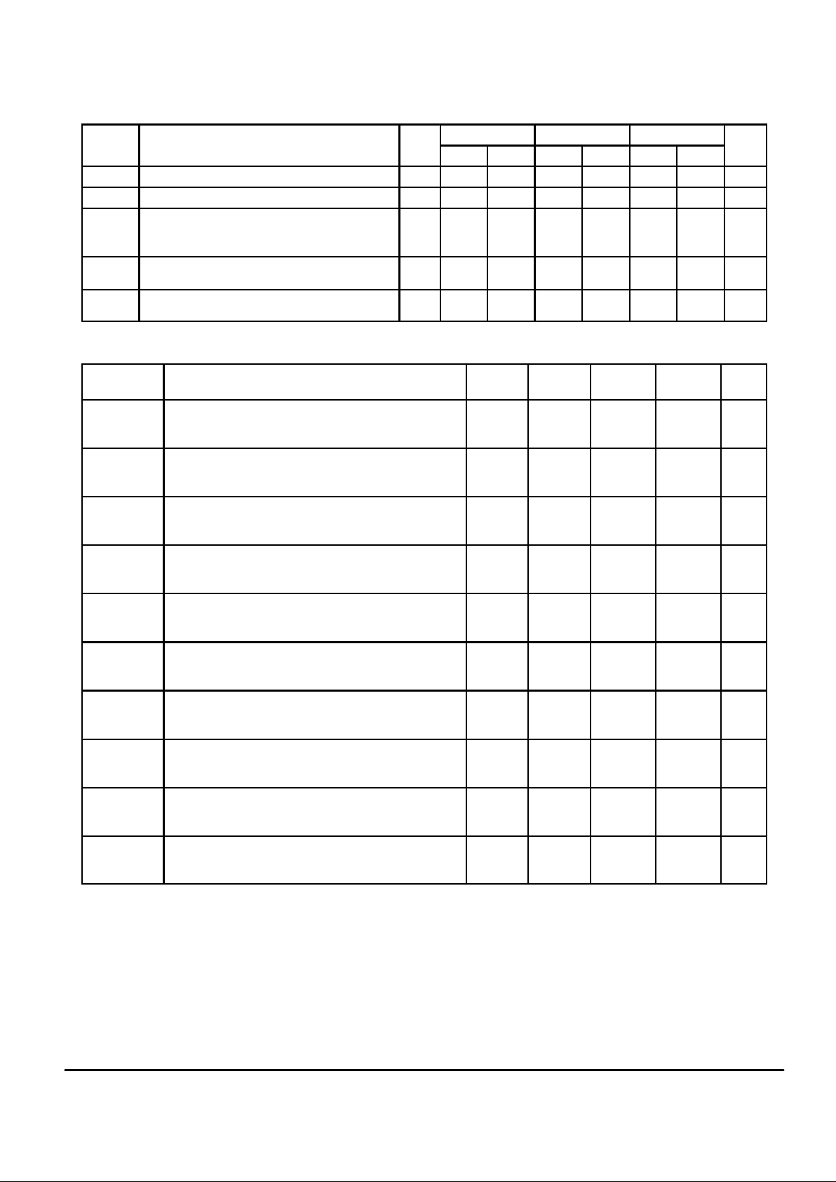
ELECTRICAL CHARACTERISTICS (continued)
V
– 40°C 25°C 85°C
Symbol Characteristic
V
DD
V
Min Max Min Max Min Max
Unit
C
in
Input Capacitance — — 10 — 10 — 10 pF
C
out
Three–State Output Capacitance — PD
out
— — 10 — 10 — 10 pF
I
DD
Quiescent Current
Vin = 0 V or V
DD
I
out
= 0 µA
3
5
9
—
—
—
800
1200
1600
—
—
—
800
1200
1600
— 1600
2400
3200
µA
I
OZ
Three–State Leakage Current — PD
out
V
out
= 0 V or 9 V
9 — ± 0.3 — ± 0.1 — ± 3.0 µA
I
OZ
Off–State Leakage Current — SW1, SW2
V
out
= 9 V
9 — 0.3 — 0.1 — 3.0 µA
SWITCHING CHARACTERISTICS (T
A
= 25°C, CL = 50 pF)
Symbol
Characteristic
Figure
No.
V
DD
V
Min Max Unit
t
TLH
Output Rise Time, MC1 and MC2 1, 6 3
5
9
—
—
—
115
60
40
ns
t
THL
Output Fall Time, MC1 and MC2 1, 6 3
5
9
—
—
—
60
34
30
ns
t
TLH
,
t
THL
Output Rise and Fall Time, LD and S/R
out
1, 6 3
5
9
—
—
—
140
80
60
ns
t
PLH
,
t
PHL
Propagation Delay Time, fin to MC1 or MC2 2, 6 3
5
9
—
—
—
125
80
50
ns
t
su
Setup Time, DATA to CLK 3 3
5
9
30
20
18
—
—
—
ns
t
su
Setup Time, CLK to ENB 3 3
5
9
70
32
25
—
—
—
ns
t
h
Hold Time, CLK to DATA 3 3
5
9
12
12
15
—
—
—
ns
t
rec
Recovery Time, ENB to CLK 3 3
5
9
5
10
20
—
—
—
ns
tr, t
f
Input Rise and Fall Times, Any Input 4 3
5
9
—
—
—
5
2
0.5
µs
t
w
Input Pulse Width, ENB and CLK 5 3
5
9
40
35
25
—
—
—
ns
Page 5

MC145149MOTOROLA
5
FREQUENCY CHARACTERISTICS (Voltages Referenced to V
SS
, CL = 50 pF, Input tr = tf = 10 ns unless otherwise indicated)
V
– 40°C 25°C 85°C
Symbol Parameter Test Conditions
V
DD
V
Min Max Min Max Min Max
Unit
f
i
Input Frequency
(fin, OSCin)
R ≥ 8, A ≥ 0, N ≥ 8
Vin = 500 mV p–p
ac coupled sine wave
3
5
9
—
—
—
6
15
15
—
—
—
6
15
15
—
—
—
6
15
15
MHz
R ≥ 8, A ≥ 0, N ≥ 8
Vin = VDD to V
SS
dc coupled square wave
3
5
9
—
—
—
6
15
15
—
—
—
6
15
15
—
—
—
6
15
15
MHz
SWITCHING W AVEFORMS
10%
90%
ANY
OUTPUT
t
TLH
t
THL
MC 50%
50%
t
PLHtPHL
V
DD
V
SS
f
in
Figure 1.
50%
50%
LAST
CLK
PREVIOUS DA TA
LATCHED
FIRST
CLK
ENB
CLK
DATA
50%
V
DD
V
SS
V
DD
V
SS
V
DD
V
SS
t
su
t
su
t
rec
t
h
10%
90%
ANY
INPUT
V
DD
V
SS
t
f
t
r
50%
ENB, CLK
V
DD
V
SS
t
w
OUTPUT
DEVICE
UNDER
TEST
C
L
*
Figure 2.
Figure 3.
Figure 4.
Figure 5. Figure 6.
* Includes all probe and fixture capacitance.
Page 6

MC145149 MOTOROLA
6
PIN DESCRIPTIONS
INPUT PINS
OSCin, OSC
out
Reference Oscillator Input/Output (Pins 15, 16)
These pins form a reference oscillator when connected to
terminals of an external parallel–resonant crystal. Frequency–setting capacitors of appropriate value must be connected from OSCin and OSC
out
to ground.
OSCin may also serve as input for an externally–generated
reference signal. The signal is typically ac coupled to OSCin,
but for signals with CMOS logic levels, dc coupling may be
used. When used with an external reference, OSC
out
should
be left open.
f
in1
, f
in2
Frequency Inputs (Pins 4, 7)
Input frequency from an external VCO output. Each rising–
edge signal on f
in1
decrements the N counter, and when ap-
propriate, the A counter of PLL 1. Similarly, f
in2
decrements
the counters of PLL 2.
These inputs have inverters biased on the linear region
which allows ac coupling for signals as low as 500 mV p–p.
With square wave signals which swing from VSS to VDD, dc
coupling may be used.
DATA, CLK
Data, Clock Inputs (Pins 5, 6)
Shift register data and clock inputs. Each low–to–high
transition on the clock pin shifts one bit of data into the on–
chip shift registers. Refer to Figure 7 for the following discussion.
The last bit entered is a steering bit that determines which
set of latches are activated. A logic high selects the latches
for PLL 1. A logic low selects PLL 2.
The second–to–last bit controls the appropriate port expander output, SW1 or SW2. A logic low forces the output
low. A logic high forces the output to the high–impedance
state.
The third–to–last bit determines which storage latch is activated. A logic low selects the ÷ A and ÷ N counter latches. A
logic high selects the reference counter latch.
When writing to either set of ÷ A and ÷ N counter latches,
20 clock cycles are typically used. However, if a byte–
oriented MCU is utilized, 24 clock cycles may be used with
the first 4 bits being “Don’t Care.”
When writing to either reference counter latch, 17 clock
cycles are typically used. However, if a byte–oriented MCU is
utilized, 24 clock cycles may be used with the first 7 bits
being “Don’t Care”.
ENB
Latch Enable Input (Pin 3)
A positive pulse on this input transfers data from the shift
registers to the selected latches, as determined by the control and steering data bits. A logic low level on this pin allows
the user to shift data into the shift registers without affecting
the data in the latches or counters. Enable is normally held
low and is pulsed high to transfer data into the latches.
OUTPUT PINS
PD
out1
, PD
out2
Single–Ended Phase Detector Outputs (Pins 19, 12)
Each single–ended (three–state) phase detector output
produces a loop error signal that is used with a loop filter to
control a VCO (see Figure 8).
Frequency fV > fR or fV Leading: Negative Pulses
Frequency fV < fR or fV Lagging: Positive Pulses
Frequency fV = fR and Phase Coincidence: High–Imped-
ance State
S/R
out
Shift Register Output (Pin 8)
This output can be connected to an external shift register
to provide band switching or control information. S/R
out
may
also be used to check the counter programming bit stream.
MC1, MC2
Modulus Control Outputs (Pins 2, 9)
Each output generates a signal by the on–chip control
logic circuitry for controlling an external dual–modulus
prescaler. The modulus control level is low at the beginning
of a count cycle and remains low until the ÷ A counter has
counted down from its programmed value. At this time,
modulus control goes high and remains high until the ÷ N
counter has counted the rest of the way down from its
programmed value (N–A additional counts since both ÷ N
and ÷ A are counting down during the first portion of the
cycle). Modulus control is then set back low, the counters are
preset to their respective programmed values, and the above
sequence is repeated. This provides for a total programmable divide value (NT) = N • P + A where P and P + 1 represent the dual–modulus prescaler divide values respectively
for high and low modulus control levels, N the number programmed into the ÷ N counter, and A the number programmed into the ÷ A counter.
Note that when a prescaler is needed, the dual–modulus
version offers a distinct advantage. The dual–modulus
prescaler allows a higher reference frequency at the phase
detector input, increasing system performance capability,
and simplifying the loop filter design.
LD1, LD2
Lock Detect Signals (Pins 1, 10)
Each output is essentially at a high logic level when the
corresponding loop is locked (fR and fV of the same phase
and frequency). Each output pulses low when the corresponding loop is out of lock (see Figure 8).
SW1, SW2
Latched Open–Drain Switch Outputs (Pins 17, 14)
The state of each output is controlled by the “SW STATE”
bit shown in Figure 7. If the bit is a logic high, the corresponding SW output assumes the high–impedance state. If the bit
is low, the SW output goes low.
To control output SW1, steering bit PLL 1/PLL 2 shown in
Figure 7 must be high. To control SW2, bit PLL 1/PLL 2 must
be low.
These outputs have an output voltage range of VSS to
15 V.
Page 7

MC145149MOTOROLA
7
POWER SUPPLY PINS
V
DD1
, V
DD2
Positive Power Supply (Pins 18, 13)
The most positive power supply potentials. Both of these
pins are connected to the substrate of the chip. Therefore,
both must be tied to the same voltage potential. This potential may range from 3 to 9 V with respect to the VSS pins.
For optimum performance, V
DD1
should be bypassed to
V
SS1
and V
DD2
bypassed to V
SS2
. That is, two separate
bypass capacitors should be utilized.
V
SS1
, V
SS2
Negative Power Supply (Pins 20, 11)
The most negative power supply potentials. Both of these
pins should be tied to ground.
Figure 7. Bit Stream Formats
÷
R
÷
A
÷
N
LAST BIT INTO
SHIFT REGISTER
LAST BIT INTO
SHIFT REGISTER
PLL 1/PLL 2
SW STATE
LOW OR “0”
LSB
MSB
LSB
PLL 1/PLL 2
SW STATE
HIGH OR “1”
LSB
MSB
MSB
NOTE: The PD output state is equal to either VDD or VSS when active. When not active, the output is high
impedance and the voltage at that pin is determined by the low–pass filter capacitor.
f
R
REFERENCE
(OSC
÷
R)
f
V
FEEDBACK
(fin
÷
N)
PD
out
LD
Figure 8. Phase Detector/Lock Detector Output Waveforms
Page 8

MC145149 MOTOROLA
8
F(s) =
ζ
=
ωn =
A)
NR1C
R1sC + 1
DEFINITIONS:
N = T otal Division Ratio in Feedback Loop
Kφ (Phase Detector Gain) = VDD/4π for PD
out
K
VCO
(VCO Gain) =
2π∆f
VCO
∆V
VCO
Damping Factor: ζ [ 1
1
C
VCOPD
out
N
ω
n
2K
φKVCO
F(s) =
ζ
=
ωn =
B)
(R1+R2)sC + 1
R2sC + 1
C
VCO
R
2
PD
out
R
1
R
1
NC(R1 + R2)
R2C+
N
K
φKVCO
0.5
ω
n
Ǔ
ǒ
KφK
VCO
K
φKVCO
RECOMMENDED READING:
Gardner, Floyd M.,
Phaselock Techniques (second edition).
New York, Wiley–Interscience, 1979.
Manassewitsch, Vadim,
Frequency Synthesizers: Theory and Design (second edition).
New York, Wiley–Interscience, 1980.
Blanchard, Alain,
Phase–Locked Loops: Application to Coherent Receiver Design.
New York, Wiley–Interscience, 1976.
Egan, William F.,
Frequency Synthesis by Phase Lock.
New York, Wiley–Interscience, 1981.
Rohde, Ulrich L.,
Digital PLL Frequency Synthesizers Theory and Design.
Englewood Cliffs, NJ, Prentice–Hall, 1983.
Berlin, Howard M.,
Design of Phase–Locked Loop Circuits, with Experiments.
Indianapolis, Howard W. Sams and Co., 1978.
Kinley, Harold,
The PLL Synthesizer Cookbook.
Blue Ridge Summit, PA, Tab Books, 1980.
AN535, Phase–Locked Loop Design Fundamentals, Motorola Semiconductor Products, Inc., 1970.
AR254, Phase–Locked Loop Design Articles, Motorola Semiconductor Products, Inc., Reprinted with permission from
Electronic Design,
1987.
for a typical design ωn (Natural Frequency)
≈
2πfr
10
(at phase detector input).
Figure 9. Phase–Locked Loop Low–Pass Filter Design
DESIGN CONSIDERA TIONS
CRYSTAL OSCILLATOR CONSIDERATIONS
The following options may be considered to provide a reference frequency to Motorola’s CMOS frequency synthesizers.
Use of a Hybrid Crystal Oscillator
Commercially available temperature–compensate crystal
oscillators (TCXOs) or crystal–controlled data clock oscillators provide very stable reference frequencies. An oscillator
capable of sinking and sourcing 50 µA at CMOS logic levels
may be direct or dc coupled to OSCin. In general, the highest
frequency capability is obtained utilizing a direct–coupled
square wave having a rail–to–rail (VDD to VSS) voltage
swing. If the oscillator does not have CMOS logic levels on
the outputs, capacitive or ac coupling to OSCin may be used.
OSC
out
, an unbuffered output, should be left floating.
For additional information about TCXOs and data clock
oscillators, please consult the latest version of the
eem Elec-
tronic Engineers Master Catalog,
the
Gold Book,
or similar
publications.
Design an Off–Chip Reference
The user may design an off–chip crystal oscillator using
ICs specifically developed for crystal oscillator applications,
such as the MC12061 MECL device. The reference signal
from the MECL device is ac coupled to OSCin. For large amplitude signals (standard CMOS logic levels), dc coupling is
used. OSC
out
, an unbuffered output, should be left floating.
In general, the highest frequency capability is obtained with a
direct–coupled square wave having rail–to–rail voltage
swing.
Use of the On–Chip Oscillator Circuitry
The on–chip amplifier (a digital inverter) along with an appropriate crystal may be used to provide a reference source
frequency. A fundamental mode crystal, parallel resonant at
Page 9

MC145149MOTOROLA
9
the desired operating frequency, should be connected as
shown in Figure 10.
For VDD= 5.0 V, the crystal should be specified for a loading capacitance, CL, which does not exceed 32 pF for frequencies to approximately 8 MHz, 20 pF for frequencies in
the area of 8 to 15 MHz, and 10 pF for higher frequencies.
These are guidelines that provide a reasonable compromise
between IC capacitance, drive capability, swamping variations in stray and IC input/output capacitance, and realistic
CL values. The shunt load capacitance, CL, presented
across the crystal can be estimated to be:
CL =
CinC
out
Cin + C
out
+ Ca + CO +
C1 • C2
C1 + C2
where
Cin= 5 pF (see Figure 11)
C
out
= 6 pF (see Figure 11)
Ca= 1 pF (see Figure 11)
CO= the crystal’s holder capacitance (see Figure 12)
C1 and C2 = external capacitors (see Figure 10)
The oscillator can be “trimmed” on–frequency by making a
portion or all of C1 variable. The crystal and associated components must be located as close as possible to the OSC
in
and OSC
out
pins to minimize distortion, stray capacitance,
stray inductance, and startup stabilization time. In some
cases, stray capacitance should be added to the value for C
in
and C
out
.
Power is dissipated in the effective series resistance of the
crystal, Re, in Figure 12. The drive level specified by the crystal manufacturer is the maximum stress that a crystal can
withstand without damaging or excessive shift in frequency.
R1 in Figure 10 limits the drive level. The use of R1 may not
be necessary in some cases (i.e., R1 = 0 Ω).
To verify that the maximum dc supply voltage does not
overdrive the crystal, monitor the output frequency as a function of voltage at OSC
out
. (Care should be taken to minimize
loading.) The frequency should increase very slightly as the
dc supply voltage is increased. An overdriven crystal will decrease in frequency or become unstable with an increase in
supply voltage. The operating supply voltage must be reduced or R1 must be increased in value if the overdriven
condition exists. The user should note that the oscillator
start–up time is proportional to the value of R1.
Through the process of supplying crystals for use with
CMOS inverters, many crystal manufacturers have developed expertise in CMOS oscillator design with crystals. Discussions with such manufacturers can prove very helpful
(see Table 1).
Figure 10. Pierce Crystal Oscillator Circuit
R1*
OSC
out
C2C1
R
f
FREQUENCY
SYNTHESIZER
*May be deleted in certain cases. See text.
OSC
in
Figure 11. Parasitic Capacitances of the Amplifier
C
in
C
out
C
a
NOTE: Values are supplied by crystal manufacturer
(parallel resonant crystal).
2
1
2
121
R
S
L
S
C
S
R
e
X
e
C
O
Figure 12. Equivalent Crystal Networks
RECOMMENDED READING
Technical Note TN–24, Statek Corp.
Technical Note TN–7, Statek Corp.
E. Hafner, “The Piezoelectric Crystal Unit – Definitions and
Method of Measurement”,
Proc. IEEE,
Vol. 57, No. 2 Feb.,
1969.
D. Kemper, L. Rosine, “Quartz Crystals for Frequency
Control”,
Electro–Technology
, June, 1969.
P. J. Ottowitz, “A Guide to Crystal Selection”,
Electronic
Design
, May, 1966.
Table 1. Partial List of Crystal Manufacturers
Name Address Phone
United States Crystal Corp.
Crystek Crystal
Statek Corp.
3605 McCart Ave., Ft. Worth, TX 76110
2351 Crystal Dr., Ft. Myers, FL 33907
512 N. Main St., Orange, CA 92668
(817) 921–3013
(813) 936–2109
(714) 639–7810
NOTE: Motorola cannot recommend one supplier over another and in no way suggests that this is a complete
listing of crystal manufacturers.
Page 10

MC145149 MOTOROLA
10
DUAL–MODULUS PRESCALING
OVERVIEW
The technique of dual–modulus prescaling is well established as a method of achieving high performance frequency
synthesizer operation at high frequencies. Basically, the
approach allows relatively low–frequency programmable
counters to be used as high–frequency programmable
counters with speed capability of several hundred MHz. This
is possible without the sacrifice in system resolution and performance that results if a fixed (single–modulus) divider is
used for the prescaler.
In dual–modulus prescaling, the lower speed counters
must be uniquely configured. Special control logic is necessary to select the divide value P or P + 1 in the prescaler
for the required amount of time (see modulus control definition). Motorola’s dual–modulus frequency synthesizers
contain this feature and can be used with a variety of dual–
modulus prescalers to allow speed, complexity, and cost to
be tailored to the system requirements. Prescalers having P,
P + 1 divide values in the range of ÷ 3/÷ 4 to ÷ 128/÷ 129 can
be controlled by most Motorola frequency synthesizers.
Several dual–modulus prescaler approaches suitable for
use with the MC145149 are:
MC12009
MC1201 1
MC12013
MC12015
MC12016
MC12017
MC12018
MC12022A
MC12032A
÷ 5/÷ 6
÷ 8/÷ 9
÷ 10/÷ 11
÷ 32/÷ 33
÷ 40/÷ 41
÷ 64/÷ 65
÷ 128/÷ 129
÷ 64/65 or ÷ 128/129
÷ 64/65 or ÷ 128/129
440 MHz
500 MHz
500 MHz
225 MHz
225 MHz
225 MHz
520 MHz
1.1 GHz
2.0 GHz
DESIGN GUIDELINES
The system total divide value, N
total
(NT) will be dictated by
the application, i.e.,
NT=
frequency into the prescaler
frequency into the phase detector
= N P + A
N is the number programmed into the ÷ N counter, A is the
number programmed into the ÷ A counter, P and P + 1 are
the two selectable divide ratios available in the dual–modulus prescalers. To have a range of NT values in sequence,
the ÷ A counter is programmed from 0 through P – 1 for a
particular value N in the ÷ N counter. N is then incremented
to N + 1 and the ÷ A is sequenced from 0 through P – 1
again.
There are minimum and maximum values that can be
achieved for NT. These values are a function of P and the
size of the ÷ N and ÷ A counters.
The constraint N ≥ A always applies. If A
max
= P – 1, then
N
min
≥ P – 1. Then N
Tmin
= (P – 1) P + A or (P – 1) P since A
is free to assume the value of 0.
N
Tmax
= N
max
P
+ A
max
To maximize system frequency capability, the dual–modulus prescaler output must go from low to high after each
group of P or P + 1 input cycles. The prescaler should divide
by P when its modulus control line is high and by P + 1 when
its modulus control is low.
For the maximum frequency into the prescaler (f
VCO
max),
the value used for P must be large enough such that:
1. f
VCO
max divided by P may not exceed the frequency
capability of fin (input to the ÷ N and ÷ A counters).
2. The period of f
VCO
divided by P must be greater than
the sum of the times:
a. Propagation delay through the dual–modulus
prescaler.
b. Prescaler setup or release time relative to its
modulus control signal.
c. Propagation time from fin to the modulus control
output for the frequency synthesizer device.
A sometimes useful simplification in the programming
code can be achieved by choosing the values for P of 8, 16,
32, or 64. For these cases, the desired value of NT results
when NT in binary is used as the program code to the ÷ N
and ÷ A counters treated in the following manner:
1. Assume the ÷ A counter contains “a” bits where 2a ≥ P.
2. Always program all higher order ÷ A counter bits above
“a” to 0.
3. Assume the ÷ N counter and the ÷ A counter (with all the
higher order bits above “a” ignored) combined into a
single binary counter of n + a bits in length (n = number
of divider stages in the ÷ N counter). The MSB of this “hypothetical” counter is to correspond to the MSB of ÷ N
and the LSB is to correspond to the LSB of ÷ A. The system divide value, NT, now results when the value of N
T
in binary is used to program the “new” n + a bit counter.
By using the two devices, several dual–modulus values
are achievable.
MC
DEVICE B
DEVICE A
DEVICE
B
MC12009 MC1201 1 MC12013DEVICE A
MC10131
MC10138
MC10154
÷
20/÷ 21
÷
50/÷ 51
÷
40/÷ 41
OR
÷
80/÷ 81
÷
64/÷ 65
OR
÷
128/÷ 129
÷
32/÷ 33
÷
80/÷ 81
÷
40/÷ 41
÷
100/÷ 101
÷
80/÷ 81
NOTE: MC12009, MC12011, and MC12013 are pin equivalent.
MC12015, MC12016, and MC12017 are pin equivalent.
Page 11

MC145149MOTOROLA
11
P ACKAGE DIMENSIONS
P SUFFIX
PLASTIC DIP
CASE 738–03
1.070
0.260
0.180
0.022
0.070
0.015
0.140
15°
0.040
1.010
0.240
0.150
0.015
0.050
0.008
0.110
0
°
0.020
25.66
6.10
3.81
0.39
1.27
0.21
2.80
0
°
0.51
27.17
6.60
4.57
0.55
1.77
0.38
3.55
15
°
1.01
0.050 BSC
0.100 BSC
0.300 BSC
1.27 BSC
2.54 BSC
7.62 BSC
MIN MINMAX MAX
INCHES MILLIMETERS
DIM
A
B
C
D
E
F
G
J
K
L
M
N
NOTES:
1. DIMENSIONING AND TOLERANCING PER ANSI
Y14.5M, 1982.
2. CONTROLLING DIMENSION: INCH.
3. DIMENSION L TO CENTER OF LEAD WHEN
FORMED PARALLEL.
4. DIMENSION B DOES NOT INCLUDE MOLD
FLASH.
-A-
C
K
N
E
GF
D
20 PL
J 20 PL
L
M
-T-
SEATING
PLANE
110
1120
0.25 (0.010) T A
M M
0.25 (0.010) T B
M M
B
D SUFFIX
SOG PACKAGE
CASE 751D–04
NOTES:
1. DIMENSIONING AND TOLERANCING PER
ANSI Y14.5M, 1982.
2. CONTROLLING DIMENSION: MILLIMETER.
3. DIMENSIONS A AND B DO NOT INCLUDE
MOLD PROTRUSION.
4. MAXIMUM MOLD PROTRUSION 0.150
(0.006) PER SIDE.
5. DIMENSION D DOES NOT INCLUDE
DAMBAR PROTRUSION. ALLOWABLE
DAMBAR PROTRUSION SHALL BE 0.13
(0.005) TOTAL IN EXCESS OF D DIMENSION
AT MAXIMUM MATERIAL CONDITION.
–A–
–B–
20
1
11
10
S
A
M
0.010 (0.25) B
S
T
D20X
M
B
M
0.010 (0.25)
P10X
J
F
G
18X
K
C
–T–
SEATING
PLANE
M
R
X 45
_
DIM MIN MAX MIN MAX
INCHESMILLIMETERS
A 12.65 12.95 0.499 0.510
B 7.40 7.60 0.292 0.299
C 2.35 2.65 0.093 0.104
D 0.35 0.49 0.014 0.019
F 0.50 0.90 0.020 0.035
G 1.27 BSC 0.050 BSC
J 0.25 0.32 0.010 0.012
K 0.10 0.25 0.004 0.009
M 0 7 0 7
P 10.05 10.55 0.395 0.415
R 0.25 0.75 0.010 0.029
__
__
Page 12

MC145149 MOTOROLA
12
Motorola reserves the right to make changes without further notice to any products herein. Motorola makes no warranty, representation or guarantee regarding
the suitability of its products for any particular purpose, nor does Motorola assume any liability arising out of the application or use of any product or circuit,
and specifically disclaims any and all liability, including without limitation consequential or incidental damages. “T ypical” parameters can and do vary in different
applications. All operating parameters, including “T ypicals” must be validated for each customer application by customer’s technical experts. Motorola does
not convey any license under its patent rights nor the rights of others. Motorola products are not designed, intended, or authorized for use as components in
systems intended for surgical implant into the body, or other applications intended to support or sustain life, or for any other application in which the failure of
the Motorola product could create a situation where personal injury or death may occur. Should Buyer purchase or use Motorola products for any such
unintended or unauthorized application, Buyer shall indemnify and hold Motorola and its officers, employees, subsidiaries, affiliates, and distributors harmless
against all claims, costs, damages, and expenses, and reasonable attorney fees arising out of, directly or indirectly, any claim of personal injury or death
associated with such unintended or unauthorized use, even if such claim alleges that Motorola was negligent regarding the design or manufacture of the part.
Motorola and are registered trademarks of Motorola, Inc. Motorola, Inc. is an Equal Opportunity/Affirmative Action Employer.
How to reach us:
USA/EUROPE: Motorola Literature Distribution; JAPAN: Nippon Motorola Ltd.; Tatsumi–SPD–JLDC, Toshikatsu Otsuki,
P.O. Box 20912; Phoenix, Arizona 85036. 1–800–441–2447 6F Seibu–Butsuryu–Center, 3–14–2 Tatsumi Koto–Ku, Tokyo 135, Japan. 03–3521–8315
MFAX: RMF AX0@email.sps.mot.com – T OUCHTONE (602) 244–6609 HONG KONG: Motorola Semiconductors H.K. Ltd.; 8B Tai Ping Industrial Park,
INTERNET: http://Design–NET.com 51 Ting Kok Road, Tai Po, N.T., Hong Kong. 852–26629298
MC145149/D
*MC145149/D*
◊
 Loading...