

Page 1
14
SEMICONDUCTOR
TECHNICAL DATA
ETR FRONT END for
C–QUAM AM STEREO
PIN CONNECTIONS
Order this document by MC13025/D
P SUFFIX
PLASTIC PACKAGE
CASE 648
16
1
D SUFFIX
PLASTIC PACKAGE
CASE 751B
(SO–16)
16
1
13
15
3
LO
Buffer
16
9
10
11
12
7
8
6
5
4
2
1
IF Amp Out
N.C. Open
Gnd
V
CLO
In
LO Output
Collector
Emitter
Base
Wideband
AGC Out
3V Ref
In
IF Amp In
Gnd
Out
In
Wideband
AGC In
V
CC
IF Amp
VCLO
4x LO
÷
4
Mixer
Wideband
AGC
(T op View)
PNP
Mixer
B
E
C
1
MOTOROLA ANALOG IC DEVICE DATA
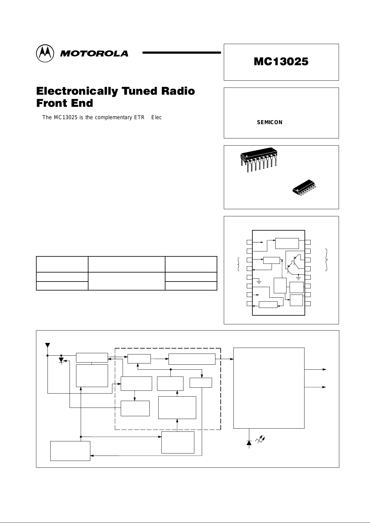
The MC13025 is the complementary ETR Electronically Tuned Radio
front–end for the second generation MC13022 C–QUAM AM stereo IF and
decoder. The MC13025 provides a high dynamic range mixer, voltage
controlled oscillator, and first IF that with the MC13022 and synthesizer form
a complete digitally controlled AM stereo tuner system. This system in turn
may drive a dual channel audio processor and high power amplifiers for car
radio or home stereo applications. Other applications include portable radio
“boom boxes”, table radios and component stereo systems.
• Operates Over a Wide Range of Supply Voltages: 6.0 V
CC
to 10 V
CC
• Wideband AGC Voltage to RF Amp for Extended Dynamic Range
• Buffered VCO Output to Frequency Synthesizer
• No External RF Amp Needed for Most Home Stereo and
Portable Radios
• IF Drive Output Matches the MC13022 for Optimum Performance
• VCO Operates at Four Times Local Oscillator Injection Frequency
ORDERING INFORMATION
Device
Operating
Temperature Range
Package
MC13025D
–
°
°
SO–16
MC13025P
T
A
= –
40° to +85°C
Plastic DIP
Simplified Block Diagram
Stereo Indicator
Right Channel
Left Channel
Variable Bandwidth IF
Amplifier with Notch Filter
and C–QUAM
AM
Stereo Decoder
MC13022
Mixer
IF Amplifier
Buffer
÷
4
Wideband
AGC
Voltage
Controlled
Oscillator
MC13025
Pin Attn.
Driver
Varactor
Tuned
Circuit
Frequency
Synthesizer
Varactor
Tuned
Circuit
RF Amplifier
Audio Out
This device contains 93 active transistors.
Motorola, Inc. 1996 Rev 0
Page 2
MC13025
2
MOTOROLA ANALOG IC DEVICE DATA
MAXIMUM RATINGS
Rating Symbol Value Unit
Supply Voltage V
CC
12 Vdc
Ambient Operating Temperature T
A
–40 to +85 °C
Storage Temperature T
stg
–65 to +150 °C
Junction Temperature T
J
150 °C
Power Dissipation
Derate above 25°C
P
D
1.25
10
W
mW/°C
ELECTRICAL CHARACTERISTICS (T
A
= 25°C, 8.0 VCC test circuit as shown in Figure 2.)
Characteristics
Pin Min Typ Max Unit
Supply Current 1 7.0 8.2 10 mAdc
3.0 V Ref, Current In 7 –50 7.0 90 µAdc
IF Out DC Current 8 0.9 1.05 1.2 mAdc
Mixer DC Current Output 4 0.70 0.77 0.82 mAdc
IF Output Amplitude, RF Input
@ 1.7 MHz, 31.6 mV
8 270 330 390 mVrms
Local Oscillator Output 10 160 181 220 mVrms
Wideband AGC Pull–Down Current 16 0.5 1.0 1.5 mAdc
PNP Darlington (DC Beta @ 5.0 mA IE) 1000 2500 –
PNP Darlington Collector Leakage (VE = VB = 8.0 V) 13 –0.13 –0.06 – µAdc
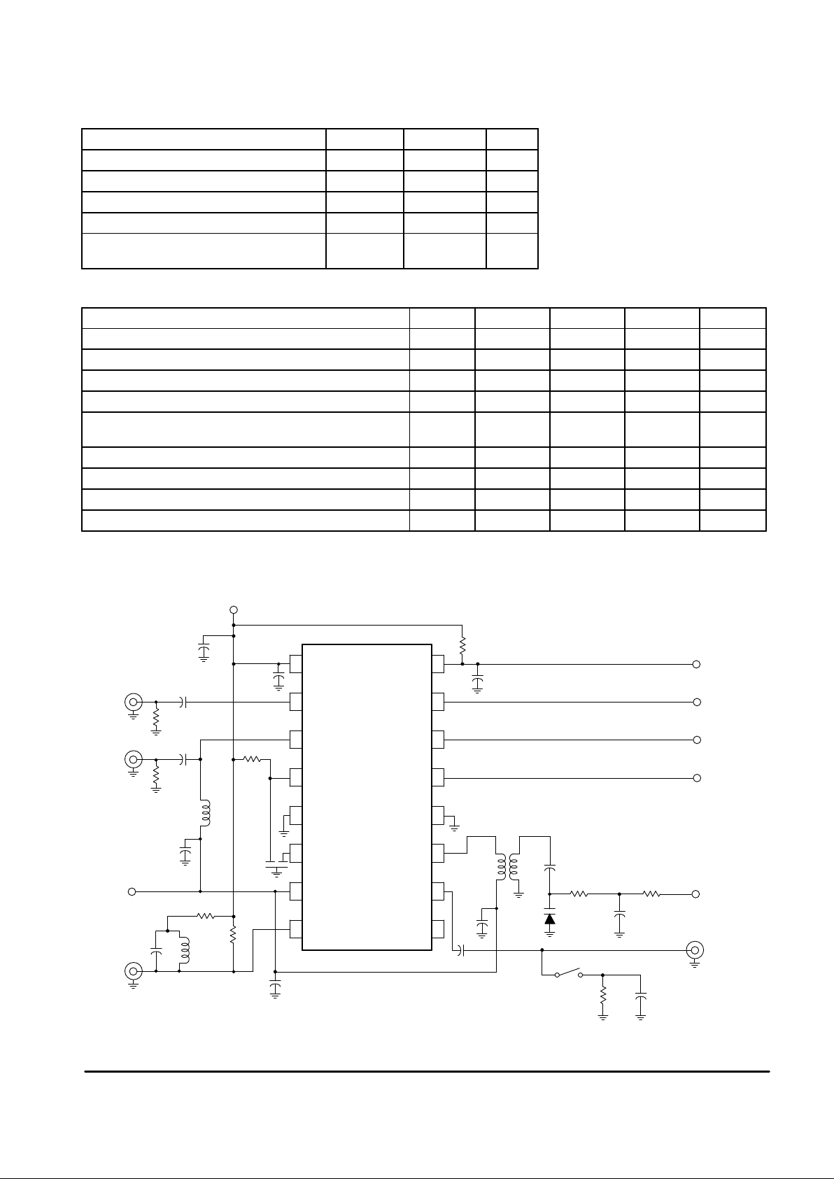
Figure 1. Test Circuit
MVAM125
Load
10 k 100
LO
Osc
Tune
1.0 k22 k
0.01
0.01
43
61
Toko
A119ANS–10287RS
430
PNP Collector
PNP Emitter
PNP Base
WB Out
47 k
0.01
NC
LO
(4x) V
CLO
Gnd
PNP
Coll
PNP
Emit
PNP
Base
Wideband
AGC Out
V
CC
Wideband
AGC In
Mixer In
Mixer Out
Gnd
0.01
V
CC
10
µ
F
1.8 k
0.01
50
WB In
Mix In
0.01
50
T oko 126ANS–7594HM
0.01
3.0 V
SFG450E
IF In
Ref
In
IF Out
10
µ
F
3.3 k
1.0 mH
510
120
IF Out
9
10
11
12
13
14
15
16
8
7
6
5
4
3
2
1
LO
3.0
mH
0.1
Page 3

MC13025
3
MOTOROLA ANALOG IC DEVICE DATA
Antenna
Tuning
Voltage
Left Audio
C7
0.01
L1
3.0 mH
1
3
R3
100 k
C8
0.01
R4
220
R12
1.0 k
C9
0.1
Q1
J310
C6
33 F
µ
R5
R7
1.0 k
C5
3.3 F
µ
C47
0.0022
C49
0.22 R29
5.6 k
Filt
R28
R41
680
C32
0.015
Q4
MPSA18
R39
39 k
R37
8.2 k
C53
0.22
R28
2.4 k
R35
150 k
C51
0.22
Hi–Pass
NRSC
V
CC
C10
8200
R11
10 k
R10
18
R9
18
Q2
MPS6515
JU3
R8
3.3 k
3
1
4
6
6
4
3
1
T1 T2
C11
5–25
C12
0.4 pF
C13
5–25
R17
3.3 k
JU1
V2
LV1235M3
V1
LV1235M3
R6
30 k
R2
22 k
C4
16
C3
5–25
V3
V1235H3
C2
30
6
4
3
1
T3
C1
0.001
LO
9
10
11
12
13
14
15
16
8
7
6
5
4
3
2
1
NC
LO Out
V
CLO
Gnd
PNP
Coil
PNP
Emit
PNP
Base
WB AGC
Out
IF Out
3.0 V
In
IF In
Gnd
Mixer Out
Mixer In
WB AGC
In
V
CC
R14
1.8 k
R15
3.3 k
C16
0.02
3
1
4
6
2
CF1
C14
0.01
C15
68
R13
8.2 k
R16
4.7 k
C17
0.01
C18
0.01
C19
10 F
µ
R18
10
C21
0.001
T5
3
2
1
R19
47
C20
47 F
µ
C22
10 F
µ
R20
13 k
R21
100 k
C24
0.01
C23
10 F
µ
C25
1.0 F
µ
Notch Filters
C26
360
C27
360
C29
360
C30
360
R22
44.2 k
R24
44.2 k
R25
44.2 k
R27
44.2 k
C28
720
R23
22.1 k
C31
720
R26
22.1 k
R45
1
2
3
4
5
6
7
8
9
10
11
12
13
14
28
27
26
25
24
23
22
21
20
19
18
17
16
15
MC13025
E
Dec In
Reg
AGC
IF In
SS
L Filter
In
Ctr
L
R
Ctr
In
R Filter
I
L–R
Q
V
CC
Loop
Blend
Gnd
Pilot In
Osc Fb
Osc In
Pilot DET In
Pilot I
Pilot Q
Filter Cntl
MC13022
C34
0.001
C35
0.001
C36
0.22
C37
100 F
µ
V
CC
R32
2.2 k
C38
0.001
C39
47 F
µ
C40
20 F
µ
R43
100 k
R33
1.0 k
X1
R34
3.9 k
C42
0.001
C41
51
0.22C43
C44
1.0 F
µ
R44
22 k
C45
10 F
µ
C46
0.47
Blend
Interstation
Mute
Stereo
LED V
CC
Force
Stereo
Filter
Control
C55
R46
C50
0.22
C48
0.0022
C33
0.015
R42
680
R31
5.6 k
R30
2.4 k
NRSC
Hi–Pass
C52
0.22
R36
150 k
C54
0.22
R38
8.2 k
R40
39 k
Signal Strength and
Stop Sense
Right Audio
Optional Filtering
Figure 2. Cascode RF ETR Application
(NRSC – Notch Filters – Optional Pilot High Pass)
Coils Toko Part Nos.
L1 Ant. Input
T1,2 RF Input
T3 VCO
T4 IF
T5 IF
126ANS–7594HM
A78RS–11081RS
A119ANS–19035RS
A7NRES–T11148N
7NRES–T1370Y
Ceramic Res. MURATA
X1
CF1
CSA3.60MGF103
SFG450E or F
SFH450E or F
T4
Q5
MPSA18
Filt
R30
Q3
MPS6515
LED
Page 4

MC13025
4
MOTOROLA ANALOG IC DEVICE DATA
P SUFFIX
PLASTIC PACKAGE
CASE 648–08
ISSUE R
D SUFFIX
PLASTIC PACKAGE
CASE 751B–05
(SO–16)
ISSUE J
OUTLINE DIMENSIONS
NOTES:
1. DIMENSIONING AND TOLERANCING PER
ANSI Y14.5M, 1982.
2. CONTROLLING DIMENSION: MILLIMETER.
3. DIMENSIONS A AND B DO NOT INCLUDE
MOLD PROTRUSION.
4. MAXIMUM MOLD PROTRUSION 0.15 (0.006)
PER SIDE.
5. DIMENSION D DOES NOT INCLUDE DAMBAR
PROTRUSION. ALLOWABLE DAMBAR
PROTRUSION SHALL BE 0.127 (0.005) TOTAL
IN EXCESS OF THE D DIMENSION AT
MAXIMUM MATERIAL CONDITION.
18
16 9
SEATING
PLANE
F
J
M
R
X 45
_
G
8 PLP
–B–
–A–
M
0.25 (0.010) B
S
–T–
D
K
C
16 PL
S
B
M
0.25 (0.010) A
S
T
DIM MIN MAX MIN MAX
INCHESMILLIMETERS
A 9.80 10.00 0.386 0.393
B 3.80 4.00 0.150 0.157
C 1.35 1.75 0.054 0.068
D 0.35 0.49 0.014 0.019
F 0.40 1.25 0.016 0.049
G 1.27 BSC 0.050 BSC
J 0.19 0.25 0.008 0.009
K 0.10 0.25 0.004 0.009
M 0 7 0 7
P 5.80 6.20 0.229 0.244
R 0.25 0.50 0.010 0.019
____
NOTES:
1. DIMENSIONING AND TOLERANCING PER ANSI
Y14.5M, 1982.
2. CONTROLLING DIMENSION: INCH.
3. DIMENSION L TO CENTER OF LEADS WHEN
FORMED PARALLEL.
4. DIMENSION B DOES NOT INCLUDE MOLD FLASH.
5. ROUNDED CORNERS OPTIONAL.
–A–
B
F
C
S
H
G
D
J
L
M
16 PL
SEATING
18
916
K
PLANE
–T–
M
A
M
0.25 (0.010) T
DIM MIN MAX MIN MAX
MILLIMETERSINCHES
A 0.740 0.770 18.80 19.55
B 0.250 0.270 6.35 6.85
C 0.145 0.175 3.69 4.44
D 0.015 0.021 0.39 0.53
F 0.040 0.70 1.02 1.77
G 0.100 BSC 2.54 BSC
H 0.050 BSC 1.27 BSC
J 0.008 0.015 0.21 0.38
K 0.110 0.130 2.80 3.30
L 0.295 0.305 7.50 7.74
M 0 10 0 10
S 0.020 0.040 0.51 1.01
____
Motorola reserves the right to make changes without further notice to any products herein. Motorola makes no warranty , representation or guarantee regarding
the suitability of its products for any particular purpose, nor does Motorola assume any liability arising out of the application or use of any product or circuit, and
specifically disclaims any and all liability, including without limitation consequential or incidental damages. “T ypical” parameters which may be provided in Motorola
data sheets and/or specifications can and do vary in different applications and actual performance may vary over time. All operating parameters, including “Typicals”
must be validated for each customer application by customer’s technical experts. Motorola does not convey any license under its patent rights nor the rights of
others. Motorola products are not designed, intended, or authorized for use as components in systems intended for surgical implant into the body, or other
applications intended to support or sustain life, or for any other application in which the failure of the Motorola product could create a situation where personal injury
or death may occur. Should Buyer purchase or use Motorola products for any such unintended or unauthorized application, Buyer shall indemnify and hold Motorola
and its officers, employees, subsidiaries, affiliates, and distributors harmless against all claims, costs, damages, and expenses, and reasonable attorney fees
arising out of, directly or indirectly, any claim of personal injury or death associated with such unintended or unauthorized use, even if such claim alleges that Motorola
was negligent regarding the design or manufacture of the part. Motorola and are registered trademarks of Motorola, Inc. Motorola, Inc. is an Equal
Opportunity/Affirmative Action Employer.
How to reach us:
USA/EUROPE/Locations Not Listed: Motorola Literature Distribution; JAPAN: Nippon Motorola Ltd.; Tatsumi–SPD–JLDC, 6F Seibu–Butsuryu–Center,
P.O. Box 20912; Phoenix, Arizona 85036. 1–800–441–2447 or 602–303–5454 3–14–2 Tatsumi Koto–Ku, Tokyo 135, Japan. 03–81–3521–8315
MFAX: RMF AX0@email.sps.mot.com – TOUCHT ONE 602–244–6609 ASIA/ PACIFIC: Motorola Semiconductors H.K. Ltd.; 8B Tai Ping Industrial Park,
INTERNET: http://Design–NET .com 51 Ting Ko k Road, Tai Po, N.T., Hong Kong. 852–26629298
MC13025/D
*MC13025/D*
◊
 Loading...