

Page 1
LOGIC DIAGRAM
V
CC1
= PIN 1
V
CC2
= PIN 16
VEE= PIN 8
5
7
10
13
15
3
2
Q
Q
64
V
EE
V
CC
C
EXT
E pos
EXTERNAL PULSE
WIDTH CONTROL
E
NEG
TRIGGER
INPUT
HI–SPEED
INPUT
TRUTH TABLE
E
PosENeg
L
L
H
H
INPUT
OUTPUT
L
H
L
H
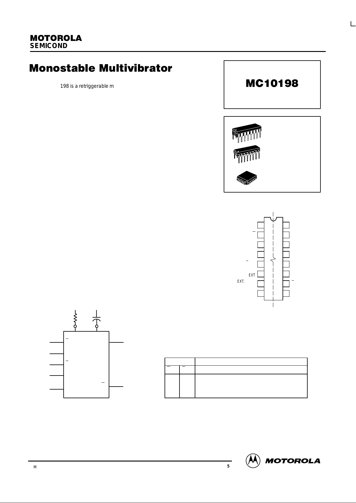
Triggers on both positive & negative input slopes
Triggers on positive input slope
Triggers on negative input slope
Trigger is disabled
R
EXT
SEMICONDUCTOR TECHNICAL DATA
3–172
REV 5
Motorola, Inc. 1996
3/93
The MC10198 is a retriggerable monostable multivibrator. T wo enable inputs
permit triggering on any combination of positive or negative edges as shown in
the accompanying table. The trigger input is buffered by Schmitt triggers
making it insensitive to input rise and fall times.
The pulse width is controlled by an external capacitor and resistor. The
resistor sets a current which is the linear discharge rate of the capacitor. Also,
the pulse width can be controlled by an external current source or voltage (see
applications information).
For high–speed response with minimum delay, a hi–speed input is also
provided. This input bypasses the internal Schmitt triggers and the output
responds within 2 nanoseconds typically.
Output logic and threshold levels are standard MECL 10,000. Test
conditions are per Table 2. Each “Precondition” referred to in Table 2 is per the
sequence of Table 1.
PD = 415 mW typ/pkg (No Load)
tpd = 4.0 ns typ Trigger Inpt to Q
2.0 ns typ Hi–Speed Input to Q
Min Timing Pulse Width PW
Qmin
10 ns typ
1
Max Timing Pulse Width PW
Qmax
>10 ms typ
2
Min Trigger Pulse Width PW
T
2.0 ns typ
Min Hi–Speed PW
HS
3.0 ns typ
Trigger Pulse Width
Enable Setup Time t
set
1.0 ns typ
Enable Hold Time t
hold
1.0 ns typ
1
C
Ext
= 0 (Pin 4 open), R
Ext
= 0
(Pin 6 to VEE)
2
C
Ext
= 10 µF, R
Ext
= 2.7 kΩ
DIP
PIN ASSIGNMENT
V
CC1
Q
Q
C
EXT
E
POS
R
EXT
EXT.PULSE
WIDTH CONTROL
V
EE
V
CC2
HIGH–SPEED
INPUT
N/C
TRIGGER INPUT
N/C
N/C
E
NEG
N/C
16
15
14
13
12
11
10
9
1
2
3
4
5
6
7
8
Pin assignment is for Dual–in–Line Package.
For PLCC pin assignment, see the Pin Conversion
T ables on page 6–11 of the Motorola MECL Data
Book (DL122/D).
L SUFFIX
CERAMIC PACKAGE
CASE 620–10
P SUFFIX
PLASTIC PACKAGE
CASE 648–08
FN SUFFIX
PLCC
CASE 775–02
Page 2
MC10198
3–173 MOTOROLAMECL Data
DL122 — Rev 6
1. At t = 0 a.) Apply V
IHmax
to Pin 5 and 10.
b.) Apply V
ILmin
to Pin 15.
c.) Ground Pin 4.
2. At t w 10 ns a.) Open Pin 1.
b.) Apply –3.0 Vdc to Pin 4.
Hold these conditions for
w
10 ns.
3. Return Pin 4 to Ground and perform test as
indicated in T able 2.
Pins 1, 16 = VCC = Ground
Pins 6, 8 = VEE = –5.2 Vdc
Outputs loaded 50 Ω to –2.0 Vdc
VIH
max
VIL
min
P1
–5.0
0
w
10 ns
t(ns)
–4.0
–3.0
–2.0
–1.0
0(Gnd)
10 20
Pin 1
open
30
TABLE 1 — PRECONDITION SEQUENCE
Pin 4 Voltage (Vdc)
w
10 ns
TABLE 2 — CONDITIONS FOR TESTING OUTPUT LEVELS
(See Table 1 for Precondition Sequence)
V
ILA max
VIL
min
P2
V
IHA max
VIL
min
P3
Pin Conditions Pin Conditions
Test P.U.T. 5 10 13 15 Test P.U.T. 5 10 13 15
Precondition Precondition
V
OH
2 VIL
min
V
OHA
2 V
IHA min
P1
V
OH
3 P1 V
OHA
3 V
ILA max
P1
Precondition Precondition
V
OL
3 VIL
min
V
OLA
3 V
ILA max
V
OL
2 P1 V
OLA
2 V
IHA min
Precondition Precondition
V
OHA
2 V
ILA max
V
OLA
2 VIL
min
V
OHA
3 V
IHA min
V
OLA
3 VIL
min
Precondition Precondition
V
OHA
2 VIL
min
V
OLA
3 P2
V
OHA
3 P3 V
OLA
2 P3
Precondition Precondition
V
OHA
2 P2 V
OLA
3 VIH
max
P2
V
OHA
3 P3 V
OLA
2 VIH
max
P3
Precondition Precondition
V
OHA
2 VIH
max
P2 V
OLA
3V
IHA minVIH max
P1
V
OHA
3 VIH
max
P3 V
OLA
2V
ILA maxVIH max
P1
Precondition Precondition
V
OHA
2 VIH
max
P1 V
OLA
3V
IH maxVIHA min
P1
V
OHA
3 VIH
max
P1 V
OLA
2V
IH maxVILA max
P1
Page 3
MC10198
MOTOROLA MECL Data
DL122 — Rev 6
3–174
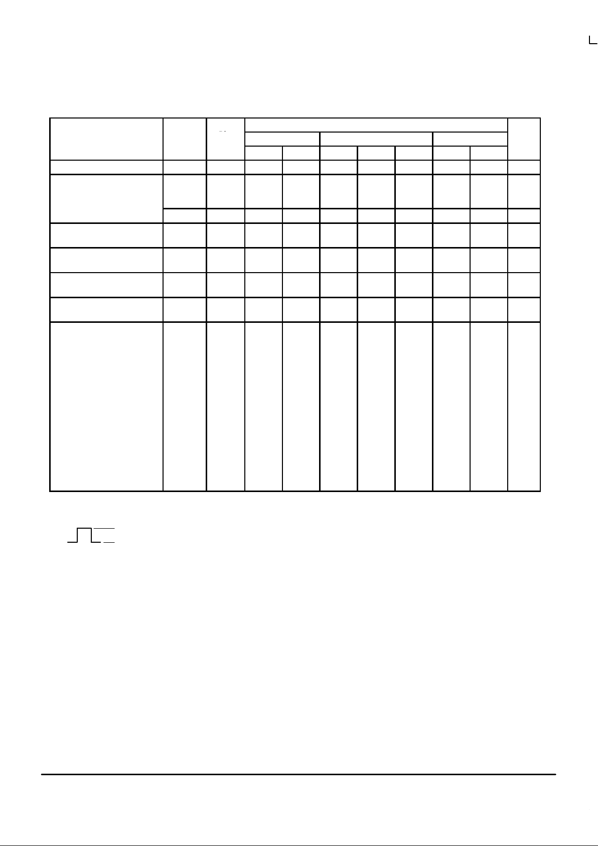
ELECTRICAL CHARACTERISTICS
Test Limits
Pin
Under
–30°C +25°C +85°C
Characteristic Symbol
Under
Test
Min Max Min Typ Max Min Max
Unit
Power Supply Drain Current I
E
8 110 80 100 110 mAdc
Input Current I
inH
5, 10
13
15
415
350
560
260
220
350
260
220
350
µAdc
I
inL
5 0.5 0.5 0.3 µAdc
Output Voltage Logic 1 V
OH
2
3
–1.060
–1.060
–0.890
–0.890
–0.960
–0.960
–0.810
–0.810
–0.890
–0.890
–0.700
–0.700
Vdc
Output Voltage Logic 0 V
OL
2
3
–1.890
–1.890
–1.675
–1.675
–1.850
–1.850
–1.650
–1.650
–1.825
–1.825
–1.615
–1.615
Vdc
Threshold Voltage Logic 1 V
OHA
2
3
–1.080
–1.080
–0.980
–0.980
–0.910
–0.910
Vdc
Threshold Voltage Logic 0 V
OLA
2
3
–1.655
–1.655
–1.630
–1.630
–1.595
–1.595
Vdc
Switching Times (50Ω Load)
Trigger Input t
T+Q+
t
T–Q+
3
3
2.5
2.5
6.5
6.5
2.5
2.5
4.0
4.0
5.5
5.5
2.5
2.5
6.5
6.5
ns
High Speed Trigger Input t
HS+Q+
3 1.5 3.2 1.5 2.0 2.8 1.5 3.2 ns
Minimum Timing Pulse Width PW
Qmin
3 10.0 ns
Maximum Timing Pulse Width PW
Qmax
3 >10 ms
Min Trigger Pulse Width PW
T
3 2.0 ns
Min Hi–Spd Trig Pulse Width PW
HS
3 3.0 ns
Rise Time (20 to 80%) 3 1.5 4.0 1.5 3.5 1.5 4.0 ns
Fall Time (20 to 80%) 3 1.5 4.0 1.5 3.5 1.5 4.0 ns
Enable Setup Time t
setup
(E) 3 1.0 ns
Enable Hold Time t
hold
(E) 3 1.0 ns
1. The monostable is in the timing mode at the time of this test.
2. C
EXT
= 0 (Pin 4 Open); R
EXT
= 0 (Pin 6 tied to VEE).
3. C
EXT
= 10µF (Pin); R
EXT
= 2.7k (Pin 6).
4.
V
IHmax
V
ILmin
P1
Page 4

MC10198
3–175 MOTOROLAMECL Data
DL122 — Rev 6
ELECTRICAL CHARACTERISTICS (continued)
TEST VOLTAGE VALUES (Volts)
@ Test Temperature V
IHmax
V
ILminVIHAminVILAmax
V
EE
–30°C –0.890 –1.890 –1.205 –1.500 –5.2
+25°C –0.810 –1.850 –1.105 –1.475 –5.2
+85°C –0.700 –1.825 –1.035 –1.440 –5.2
Pin
TEST VOLTAGE APPLIED TO PINS LISTED BELOW
Characteristic Symbol
Und
er
Test
V
IHmax
V
ILminVIHAminVILAmax
V
EE
(VCC)
Gnd
Power Supply Drain Current I
E
8 6, 8 1, 4, 16
Input Current I
inH
5, 10
13
15
5,10
13
15
6, 8
6, 8
6, 8
1, 4, 16
1, 4, 16
1, 4, 16
I
inL
5 5 6, 8 1, 4, 16
Output Voltage Logic 1 V
OH
2
3
13 (4.)
13 6, 8
6, 8
1, 4, 16
1, 4, 16
Output Voltage Logic 0 V
OL
2
3
13 (4.)
13
6, 8
6, 8
1, 4, 16
1, 4, 16
Threshold Voltage Logic 1 V
OHA
2
3
15
15 6, 8
6, 8
1, 16, 4
1, 16, 4
Threshold Voltage Logic 0 V
OLA
2
3
15
15
6, 8
6, 8
1, 16, 4
1, 16, 4
Switching Times (50Ω Load) +1.11V Pulse In Pulse Out –3.2 V +2.0 V
Trigger Input t
T+Q+
t
T–Q+
3
3
10
5
13
13
3
3
6, 8
6, 8
1, 16, 4
1, 16, 4
High Speed Trigger Input t
HS+Q+
3 15 3 6, 8 1, 16, 4
Minimum Timing Pulse Width PW
Qmin
3 Note 2. 6, 8 1, 16, 4
Maximum Timing Pulse Width PW
Qmax
3 Note 3. 6, 8 1, 16, 4
Minimum Trigger Pulse Width PW
T
3 13 3 6, 8 1, 16, 4
Minimum Hi–Spd Trigger Pulse Width PW
HS
3 15 3 6, 8 1, 16, 4
Rise Time (20 to 80%) 3 6, 8 1, 16, 4
Fall Time (20 to 80%) 3 6, 8 1, 16, 4
Enable Setup Time t
setup
(E) 3 5 3 6, 8 1, 16, 4
Enable Hold Time t
hold
(E) 3 5 3 6, 8 1, 16, 4
1. The monostable is in the timing mode at the time of this test.
2. C
EXT
= 0 (Pin 4 Open); R
EXT
= 0 (Pin 6 tied to VEE).
3. C
EXT
= 10µF (Pin); R
EXT
= 2.7k (Pin 6).
4.
V
IHmax
V
ILmin
P1
Each MECL 10,000 series circuit has been designed to meet the dc specifications shown in the test table, after thermal equilibrium has been
established. The circuit is in a test socket or mounted on a printed circuit board and transverse air flow greater than 500 linear fpm is maintained.
Outputs are terminated through a 50–ohm resistor to –2.0 volts. Test procedures are shown for only one gate. The other gates are tested in the
same manner.
Page 5

MC10198
MOTOROLA MECL Data
DL122 — Rev 6
3–176
SWITCHING TIME TEST CIRCUIT AND WAVEFORMS @ 25°C
50–ohm termination to ground located
in each scope channel input.
All input and output cables to the scope
are equal lengths of 50–ohm coaxial
cable. Wire length should be < 1/4 inch
from TPin to input pin and TP
out
to
output pin.
Unused outputs are tied to a
50–ohm resistor to ground.
High–Speed
Trigger Input
TP
out
External Pulse
Width Control
E
Pos
5
0.1 µF
V
CC1
= V
CC2
= +2.0 Vdc
0.1
µ
F
Coax
V
in
TP
in
Input
Pulse Generator
R
Ext
C
Ext
Hi–Speed Input
Trigger Input
6
E
Neg
4
7
10
13
15
Coax
25 µF
VEE = –3.2 Vdc
V
out
2
Q
Q
3
0.1
µ
F
+1.11 V
Input Pulse
t+ = t– = 2.0
±
0.2 ns
(20 to 80%)
t
HS+Q+
Q
PW
HS
PW
Q
50%
50%
PW
T
Q
Trigger Input
t
T+Q+
E
Pos
50%
50%
t
T–Q+
PW
Q
t
setup (E)
t
Hold(E)
Page 6

MC10198
3–177 MOTOROLAMECL Data
DL122 — Rev 6
APPLICATIONS INFORMATION
Circuit Operation:
1.PULSE WIDTH TIMING — The pulse width is determined by the external resistor and capacitor. The
MC10198 also has an internal resistor (nominally 284
ohms) that can be used in series with R
Ext
. Pin 7, the
external pulse width control, is a constant voltage node
(–3.60 V nominally). A resistance connected in series
from this node to VEE sets a constant timing current IT.
This current determines the discharge rate of the capacitor:
where
∆T = pulse width
∆V = 1.9 V change in capacitor voltage
Then:
If R
Ext
+ R
Int
are in series to VEE:
IT = [(–3.60 V) – (–5.2 V)] ÷ [R
Ext
+ 284 Ω]
IT = 1.6 V/(R
Ext
+ 284)
The timing equation becomes:
∆T = [(C
Ext
)(1.9 V)] ÷ [1.6 V/(R
Ext
+ 284)]
∆T = C
Ext
(R
Ext
+ 284) 1.19
where ∆T = Sec
R
Ext
= Ohms
C
Ext
= Farads
Figure 2 shows typical curves for pulse width
versus C
Ext
and R
Ext
(total resistance includes R
Int
).
Any low leakage capacitor can be used and R
Ext
can
vary from 0 to 16 k–ohms.
2.TRIGGERING —The E
pos
and E
Neg
inputs control the
trigger input. The MC10198 can be programmed to trigger on the positive edge, negative edge, or both. Also,
the trigger input can be totally disabled. The truth table
is shown on the first page of the data sheet.
The device is totally retriggerable. However, as
duty cycle approaches 100%, pulse width jitter can
occur due to the recovery time of the circuit. Recovery
time is basically dependent on capacitance C
Ext
.
Figure 3 shows typical recovery time versus capacitance at IT = 5 mA.
IT = C
Ext
∆V
∆T
∆T = C
Ext
1.9 V
I
T
VEE = –5.2 V
–3.60 V External
Pulse Width Control
284
Ω
R
Int
MC10198
R
Ext
FIGURE 1 —
C
Ext
6
4
7
10 k
Ω
R
Ext
= 0
3 k
Ω
500
Ω
C
Ext
– TIMING CAPACITANCE
10 pF
10
FIGURE 2 – TIMING PULSE WIDTH versus C
Ext
and R
Ext
100
10
1
0.1
µ
F
100
1000 pF100 pF 0.01 µF
NOTE: TOTAL RESISTANCE
= R
Ext
+ R
Int
PULSE WIDTH ( s)
C
Ext
– TIMING CAPACITANCE
0.01
µ
F100 pF 1000 pF
100 ns
0.1 µF
10 µs
1
µ
s
1 ns
10 ns
10 pF
FIGURE 3 — RECOVERY TIME versus C
Ext
@ IT = 5 mA
RECOVERY TIME
µ
Page 7

MC10198
MOTOROLA MECL Data
DL122 — Rev 6
3–178
3.HI–SPEED INPUT — This input is used for stretching
very narrow pulses with minimum delay between the
output pulse and the trigger pulse. The trigger input
should be disabled when using the high–speed input.
The MC10198 triggers on the rising edge, using this input, and input pulse width should narrow, typically less
than 10 nanoseconds.
USAGE RULES:
1.Capacitor lead lengths should be kept very short to minimize ringing due to fast recovery rise times.
2.The E
inputs should not be tied to ground to establish a
high logic level. A resistor divider or diode can be used
to establish a –0.7 to –0.9 voltage level.
3.For optimum temperature stability; 0.5 mA is the best timing current IT. The device is designed to have a constant
voltage at the EXTERNAL PULSE WIDTH CONTROL
over temperature at this current value.
4.Pulse Width modulation can be attained with the EXTERNAL PULSE WIDTH CONTROL. The timing current can
be altered to vary the pulse width. Two schemes are:
a. The internal resistor is not used. A dependent cur-
rent source is used to set the timing current as
shown in Figure 4. A graph of pulse width versus
timing current (C
Ext
= 13 pF) is shown in Figure 5.
b. A control voltage can also be used to vary the
pulse width using an additional resistor (Figure 6).
The current (IT + IC) is set by the voltage drop
across R
Int
+ R
Ext
. The control current IC modifies
IT and alters the pulse width. Current IC should
never force IT to zero. RC typically 1 kΩ.
FIGURE 5 — PULSE WIDTH versus IT @ C
Ext
= 13 pF
0.01 mA 0.1 mA 1 mA 10 mA
1000
100
10
PULSE WIDTH (ns)
MC10198
FIGURE 4 —
C
Ext
7
4
I
FIGURE 6 —
–5.2 V
Control
Voltage
284
R
Ext
C
Ext
6
4
7
IT + I
C
I
T
I
C
–3.6
V
R
C
IT – TIMING CURRENT
Page 8

MC10198
3–179 MOTOROLAMECL Data
DL122 — Rev 6
5.The MC10198 can be made non–retriggerable. The Q
output is fed back to disable the trigger input during the
triggered state (Logic Diagram). Figure 7 shows a positive triggered configuration; a similar configuration can
be made for negative triggering.
FIGURE 7 —
–0.9 V
Q
Q
64
V
EE
V
CC
E
Pos
External Pulse
Width Control
E
Neg
Trigger
Input
Hi–Speed
Input
R
Ext
C
Ext
Page 9

MC10198
MOTOROLA MECL Data
DL122 — Rev 6
3–180
OUTLINE DIMENSIONS
FN SUFFIX
PLASTIC PLCC PACKAGE
CASE 775–02
ISSUE C
NOTES:
1. DATUMS –L–, –M–, AND –N– DETERMINED
WHERE TOP OF LEAD SHOULDER EXITS PLASTIC
BODY AT MOLD PARTING LINE.
2. DIMENSION G1, TRUE POSITION TO BE
MEASURED AT DATUM –T–, SEATING PLANE.
3. DIMENSIONS R AND U DO NOT INCLUDE MOLD
FLASH. ALLOWABLE MOLD FLASH IS 0.010 (0.250)
PER SIDE.
4. DIMENSIONING AND TOLERANCING PER ANSI
Y14.5M, 1982.
5. CONTROLLING DIMENSION: INCH.
6. THE PACKAGE TOP MAY BE SMALLER THAN THE
PACKAGE BOTTOM BY UP TO 0.012 (0.300).
DIMENSIONS R AND U ARE DETERMINED AT THE
OUTERMOST EXTREMES OF THE PLASTIC BODY
EXCLUSIVE OF MOLD FLASH, TIE BAR BURRS,
GATE BURRS AND INTERLEAD FLASH, BUT
INCLUDING ANY MISMATCH BETWEEN THE TOP
AND BOTTOM OF THE PLASTIC BODY.
7. DIMENSION H DOES NOT INCLUDE DAMBAR
PROTRUSION OR INTRUSION. THE DAMBAR
PROTRUSION(S) SHALL NOT CAUSE THE H
DIMENSION TO BE GREATER THAN 0.037 (0.940).
THE DAMBAR INTRUSION(S) SHALL NOT CAUSE
THE H DIMENSION TO BE SMALLER THAN 0.025
(0.635).
–M–
–N–
–L–
Y BRK
W
V
D
D
S
L–M
M
0.007 (0.180) N
S
T
S
L–M
M
0.007 (0.180) N
S
T
S
L–M
S
0.010 (0.250) N
S
T
X
G1
B
U
Z
VIEW D–D
20 1
S
L–M
M
0.007 (0.180) N
S
T
S
L–M
M
0.007 (0.180) N
S
T
S
L–M
S
0.010 (0.250) N
S
T
C
G
VIEW S
E
J
R
Z
A
0.004 (0.100)
–T–
SEATING
PLANE
S
L–M
M
0.007 (0.180) N
S
T
S
L–M
M
0.007 (0.180) N
S
T
H
VIEW S
K
K1
F
G1
DIM MIN MAX MIN MAX
MILLIMETERSINCHES
A 0.385 0.395 9.78 10.03
B 0.385 0.395 9.78 10.03
C 0.165 0.180 4.20 4.57
E 0.090 0.110 2.29 2.79
F 0.013 0.019 0.33 0.48
G 0.050 BSC 1.27 BSC
H 0.026 0.032 0.66 0.81
J 0.020 ––– 0.51 –––
K 0.025 ––– 0.64 –––
R 0.350 0.356 8.89 9.04
U 0.350 0.356 8.89 9.04
V 0.042 0.048 1.07 1.21
W 0.042 0.048 1.07 1.21
X 0.042 0.056 1.07 1.42
Y ––– 0.020 ––– 0.50
Z 2 10 2 10
G1 0.310 0.330 7.88 8.38
K1 0.040 ––– 1.02 –––
____
Page 10

MC10198
3–181 MOTOROLAMECL Data
DL122 — Rev 6
OUTLINE DIMENSIONS
P SUFFIX
PLASTIC DIP PACKAGE
CASE 648–08
ISSUE R
NOTES:
1. DIMENSIONING AND TOLERANCING PER ANSI
Y14.5M, 1982.
2. CONTROLLING DIMENSION: INCH.
3. DIMENSION L TO CENTER OF LEADS WHEN
FORMED PARALLEL.
4. DIMENSION B DOES NOT INCLUDE MOLD FLASH.
5. ROUNDED CORNERS OPTIONAL.
–A–
B
F
C
S
H
G
D
J
L
M
16 PL
SEATING
18
916
K
PLANE
–T–
M
A
M
0.25 (0.010) T
DIM MIN MAX MIN MAX
MILLIMETERSINCHES
A 0.740 0.770 18.80 19.55
B 0.250 0.270 6.35 6.85
C 0.145 0.175 3.69 4.44
D 0.015 0.021 0.39 0.53
F 0.040 0.70 1.02 1.77
G 0.100 BSC 2.54 BSC
H 0.050 BSC 1.27 BSC
J 0.008 0.015 0.21 0.38
K 0.110 0.130 2.80 3.30
L 0.295 0.305 7.50 7.74
M 0 10 0 10
S 0.020 0.040 0.51 1.01
____
L SUFFIX
CERAMIC DIP PACKAGE
CASE 620–10
ISSUE V
NOTES:
1. DIMENSIONING AND TOLERANCING PER
ANSI Y14.5M, 1982.
2. CONTROLLING DIMENSION: INCH.
3. DIMENSION L TO CENTER OF LEAD WHEN
FORMED PARALLEL.
4. DIMENSION F MAY NARROW TO 0.76 (0.030)
WHERE THE LEAD ENTERS THE CERAMIC
BODY.
–A–
–B–
–T–
F
E
G
N
K
C
SEATING
PLANE
16 PLD
S
A
M
0.25 (0.010) T
16 PLJ
S
B
M
0.25 (0.010) T
M
L
DIM MIN MAX MIN MAX
MILLIMETERSINCHES
A 0.750 0.785 19.05 19.93
B 0.240 0.295 6.10 7.49
C ––– 0.200 ––– 5.08
D 0.015 0.020 0.39 0.50
E 0.050 BSC 1.27 BSC
F 0.055 0.065 1.40 1.65
G 0.100 BSC 2.54 BSC
H 0.008 0.015 0.21 0.38
K 0.125 0.170 3.18 4.31
L 0.300 BSC 7.62 BSC
M 0 15 0 15
N 0.020 0.040 0.51 1.01
____
16 9
18
Motorola reserves the right to make changes without further notice to any products herein. Motorola makes no warranty , representation or guarantee regarding
the suitability of its products for any particular purpose, nor does Motorola assume any liability arising out of the application or use of any product or circuit, and
specifically disclaims any and all liability, including without limitation consequential or incidental damages. “T ypical” parameters which may be provided in Motorola
data sheets and/or specifications can and do vary in different applications and actual performance may vary over time. All operating parameters, including “Typicals”
must be validated for each customer application by customer’s technical experts. Motorola does not convey any license under its patent rights nor the rights of
others. Motorola products are not designed, intended, or authorized for use as components in systems intended for surgical implant into the body, or other
applications intended to support or sustain life, or for any other application in which the failure of the Motorola product could create a situation where personal injury
or death may occur. Should Buyer purchase or use Motorola products for any such unintended or unauthorized application, Buyer shall indemnify and hold Motorola
and its officers, employees, subsidiaries, affiliates, and distributors harmless against all claims, costs, damages, and expenses, and reasonable attorney fees
arising out of, directly or indirectly, any claim of personal injury or death associated with such unintended or unauthorized use, even if such claim alleges that
Motorola was negligent regarding the design or manufacture of the part. Motorola and are registered trademarks of Motorola, Inc. Motorola, Inc. is an Equal
Opportunity/Affirmative Action Employer.
How to reach us:
USA/EUROPE/Locations Not Listed: Motorola Literature Distribution; JAPAN: Nippon Motorola Ltd.; Tatsumi–SPD–JLDC, 6F Seibu–Butsuryu–Center,
P.O. Box 5405, Denver, Colorado 80217. 303–675–2140 or 1–800–441–2447 3–14–2 Tatsumi Koto–Ku, Tokyo 135, Japan. 81–3–3521–8315
Mfax: RMFAX0@email.sps.mot.com – TOUCHT ONE 602–244–6609 ASIA/PACIFIC: Motorola Semiconductors H.K. Ltd.; 8B Tai Ping Industrial Park,
INTERNET: http://Design–NET.com 51 Ti ng Kok Road, Tai Po, N.T., Hong Kong. 852–26629298
MC10198/D
*MC10198/D*
◊
 Loading...