

Page 1
MBR7xx, MBRF7xx & MBRB7xx Series
Vishay Semiconductors
formerly General Semiconductor
Document Number 88680 www.vishay.com
03-Mar-03 1
Schottky Barrier Rectifier
Reverse V olta ge 35 to 60V
Forward Current 7.5A
0.08
(2.032)
0.24
(6.096)
0.42
(10.66)
0.63
(17.02)
0.12
(3.05)
0.33
(8.38)
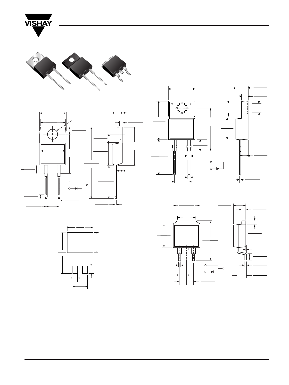
Mounting Pad Layout TO-263AB
0.380 (9.65)
0.411 (10.45)
0.320 (8.13)
0.360 (9.14)
0.591 (15.00)
0.624 (15.85)
1
2
0.245 (6.22)
MIN
K
0.027 (0.686)
0.037 (0.940)
0.105 (2.67)
0.095 (2.41)
0.205 (5.20)
0.195 (4.95)
K
0.160 (4.06)
0.190 (4.83)
0.045 (1.14)
0.055 (1.40)
0.021 (0.53)
0.014 (0.36)
0.110 (2.79)
0.140 (3.56)
0.090 (2.29)
0.110 (2.79)
0.047 (1.19)
0.055 (1.40)
PIN 1
PIN 2
K - HEATSINK
0-0.01 (0-0.254)
0.060 (1.52)
0.405 (10.27)
0.383 (9.72)
0.191 (4.85)
0.171 (4.35)
0.600 (15.5)
0.580 (14.5)
0.560 (14.22)
0.530 (13.46)
0.037 (0.94)
0.027 (0.69)
0.140 (3.56)
0.130 (3.30)
0.350 (8.89)
0.330 (8.38)
0.188 (4.77)
0.172 (4.36)
0.110 (2.80)
0.100 (2.54)
0.131 (3.39)
0.122 (3.08)
0.110 (2.80)
0.100 (2.54)
0.022 (0.55)
0.014 (0.36)
0.205 (5.20)
0.195 (4.95)
12
PIN
DIA.
DIA.
PIN 1
PIN 2
0.676 (17.2)
0.646 (16.4)
ITO-220AC (MBRF7xx)
TO-220AC (MBR7xx)
Dimensions in inches
and (millimeters)
TO-263AB (MBRB7xx)
0.154 (3.91)
0.148 (3.74)
DIA.
0.113 (2.87)
0.103 (2.62)
0.185 (4.70)
0.175 (4.44)
0.055 (1.39)
0.045 (1.14)
0.145 (3.68)
0.135 (3.43)
0.350 (8.89)
0.330 (8.38)
0.160 (4.06)
0.140 (3.56)
0.037 (0.94)
0.027 (0.68)
0.205 (5.20)
0.195 (4.95)
0.560 (14.22)
0.530 (13.46)
0.022 (0.56)
0.014 (0.36)
0.110 (2.79)
0.100 (2.54)
12
1.148 (29.16)
1.118 (28.40)
0.105 (2.67)
0.095 (2.41)
0.410 (10.41)
0.390 (9.91)
0.635 (16.13)
0.625 (15.87)
0.603 (15.32)
0.573 (14.55)
PIN
0.415 (10.54) MAX.
PIN 1
PIN 2
CASE
0.370 (9.40)
0.360 (9.14)
Mechanical Data
Case: JEDEC TO-220A C , ITO-220A C & TO-263AB
molded plastic body
Terminals: Plated leads, solderable per
MIL-STD-750, Method 2026
Polarity: As marked
Mounting Position: Any
Mounting T orque: 10 in-lbs maximum
Weight: 0.08 ounce, 2.24 grams
Features
• Plastic package has Underwriters Laboratory
Flammability Classifications 94V-0
• Metal silicon junction, majority carrier conduction
• Low power loss, high efficiency
• Guardring for overvoltage protection
• For use in low voltage, high frequency inverters,
free wheeling, and polarity protection applications
• High temperature soldering guaranteed:
250°C/10 seconds, 0.25" (6.35mm) from case
Page 2
MBR7xx, MBRF7xx & MBRB7xx Series
Vishay Semiconductors
formerly General Semiconductor
www.vishay.com Document Number 88680
2 03-Mar-03
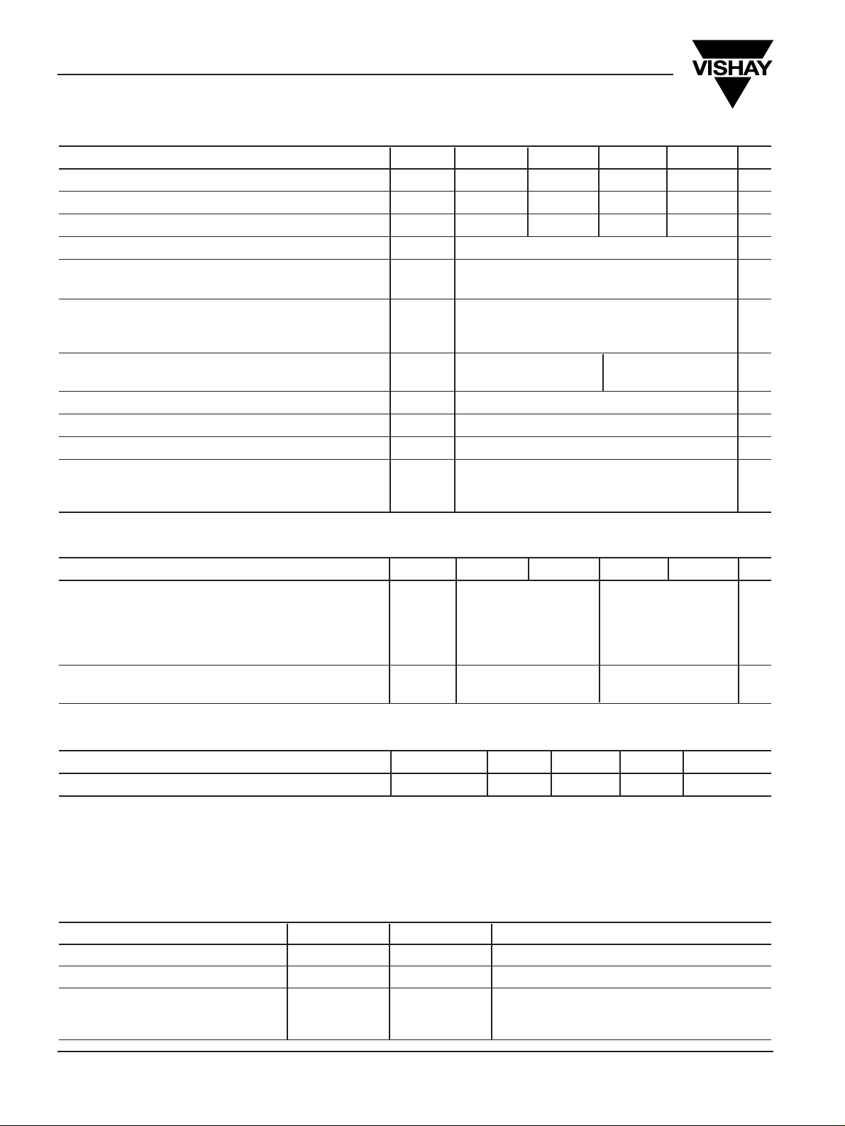
Maximum Ratings (T
C
= 25°C unless otherwise noted)
Parameter Symbol
MBR735 MBR745 MBR750 MBR760
Unit
Maximum repetitive peak reverse voltage V
RRM
35 45 50 60 V
Working peak reverse voltage V
RWM
35 45 50 60 V
Maximum DC blocking voltage V
DC
35 45 50 60 V
Maximum average forward rectified current
(SEE FIG.1)
I
F(AV)
7.5 A
Peak repetitive forward current (sq.wave, 20 KHz)
at TC= 105°C
I
FRM
15 A
Peak forward surge current
8.3ms single half sine-wave superimposed I
FSM
150 A
on rated load (JEDEC Method)
Peak repetitive reverse current
at tp= 2.0µs, 1KH
Z
I
RRM
1.0 0.5 A
Voltage rate of change (rated VR) dv/dt 10,000 V/µs
Operating junction temperature range T
J
–65 to +150 °C
Storage temperature range T
STG
–65 to +175 °C
RMS Isolation voltage (MBRF type only) from terminals to 4500
(NOTE 1)
heatsink with t = 1.0 second, RH ≤ 30% V
ISOL
3500
(NOTE 2)
V
1500
(NOTE 3)
Electrical Characteristics(T
C
= 25°C unless otherwise noted)
Parameter Symbol
MBR735 MBR745 MBR750 MBR760
Unit
Maximum instantaneous forward voltage
(Note 4)
at IF = 7.5A, TC = 25°C – 0.75
at I
F
= 7.5A, TC = 125°C V
F
0.57 0.65 V
at I
F
= 15A, TC = 25°C 0.84 –
at IF = 15A, TC = 125°C 0.72 –
Maximum reverse current T
C
= 25°C 0.1 0.5
at DC blocking voltage TC = 125°C
I
R
15 50
mA
Thermal Characteristics(T
C
= 25°C unless otherwise noted)
Parameter Symbol MBR MBRF MBRB Unit
Thermal resistance from junction to case R
ΘJC
3.0 5.0 3.0 °C/W
Notes:
(1) Clip mounting (on case), where lead does not overlap heatsink with 0.110” offset
(2) Clip mounting (on case), where leads do overlap heatsink
(3) Screw mounting with 4-40 screw, where washer diameter is ≤ 4.9 mm (0.19”)
(4) Pulse test: 300µs pulse width, 1% duty cycle
Ordering Information
Product Case Package Code Package Option
MBR735 - MBR760 TO-220AC 45 Anti-Static tube, 50/tube, 2K/carton
MBRF735 - MBRF760 ITO-220AC 45 Anti-Static tube, 50/tube, 2K/carton
31 13” reel, 800/reel, 4.8K/carton
MBRB735 - MBRB760 TO-263AB 45 Anti-Static tube, 50/tube, 2K/carton
81 Anti-Static 13” reel, 800/reel, 4.8K/carton
Page 3
MBR7xx, MBRF7xx & MBRB7xx Series
Vishay Semiconductors
formerly General Semiconductor
Document Number 88680 www.vishay.com
03-Mar-03 3
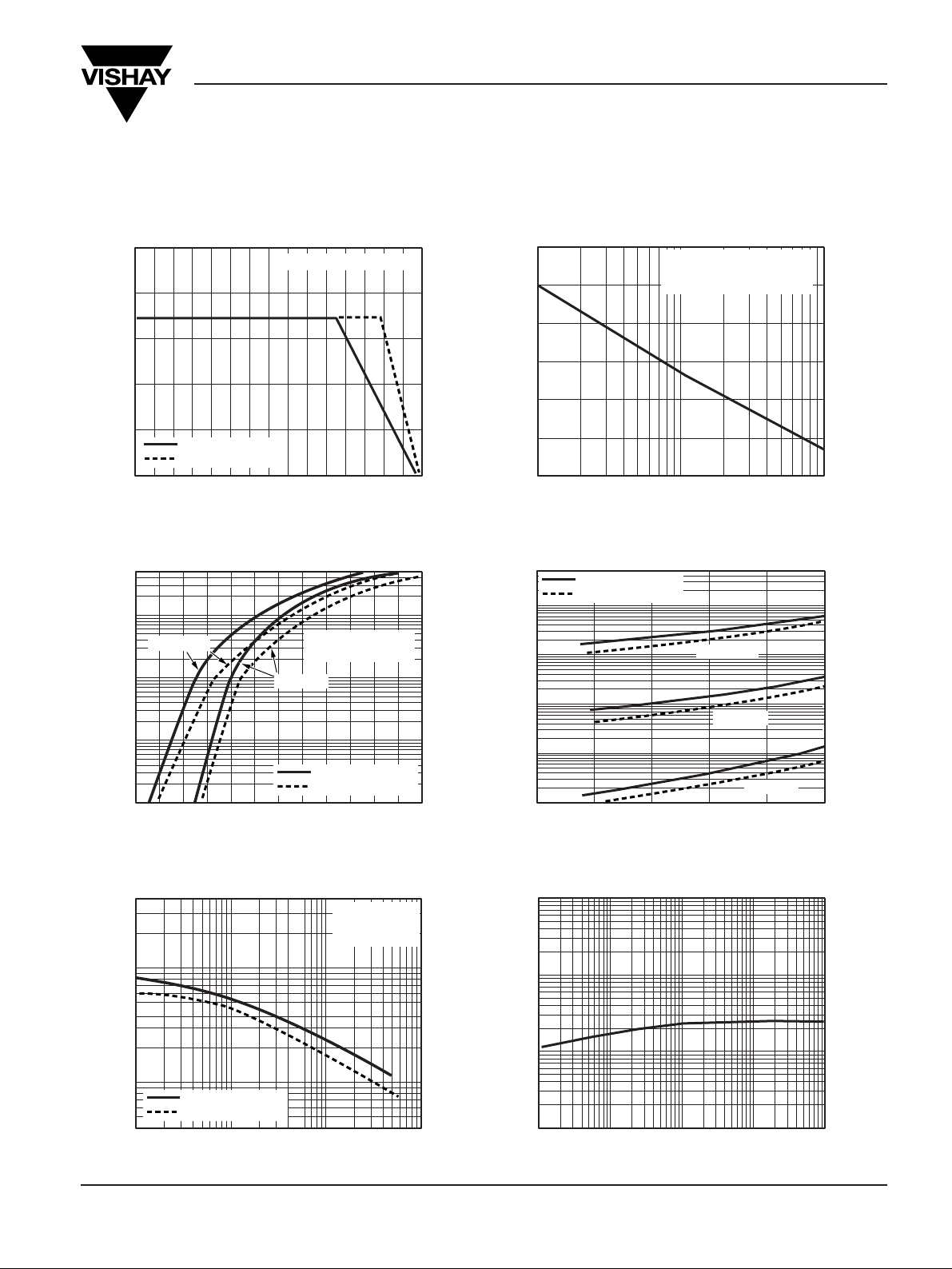
Ratings and
Characteristic Curves(T
A
= 25°C unless otherwise noted)
Case Temperature (°C)
Fig. 1 – Forward Current
Derating Curve
Average Forward Current (A)
Fig. 3 – Typical Instantaneous
Forward Characteristics
Instantaneous Forward Voltage (V)
Instantaneous Forward Current (A)
Percent of Rated Peak Reverse Voltage (%)
Instantaneous Reverse Current (mA)
Fig. 4 – Typical Reverse
Characteristics
Fig. 6 – Typical T ransient Thermal
Impedance
1
10
100
50
25
75
100
125
150
175
Number of Cycles at 60 H
Z
t, Pulse Duration (sec.)
Fig. 2 – Maximum Non-Repetitive
Peak Forward Surge Current
Peak Forward Surge Current (A)
TJ = TJ max.
8.3ms Single Half Sine-Wave
(JEDEC Method)
0.01
0.1
0.1
0.2
0.3
0.4
0.5
0.6
0.7
0.8
0.9
1.0
1.1
1.2
0
1
10
50
TJ = 125°C
TJ = 25°C
Pulse Width = 300µs
1% Duty Cycle
0
20
40
60
80
100
0.001
0.01
0.1
1
10
50
MBR735 - MBR745
MBR750 & MBR760
TJ = 25°C
TJ = 75°C
TJ = 125°C
0.1
1
10
100
40
100
1,000
4,000
Reverse Voltage (V)
Junction Capacitance (pF)
Transient Thermal Impedance (°CW)
Fig. 5 – Typical Junction
Capacitance
TJ = 25°C
f = 1.0MH
Z
Vsig = 50MVp-p
0.01
0.1
1
10
100
0.1
1
10
100
0
50
100
150
0
2
4
6
8
10
Resistive or Inductive Load
MBR735 - MBR745
MBR750 & MBR760
MBR735 - MBR745
MBR750 & MBR760
MBR735 - MBR745
MBR750 & MBR760
 Loading...