

Page 1
Macroblock,
AC IN~
V
drop between
AC IN~
R
R2 R3 To Pin 10
Preliminary
Transformerless AC/DC Constant Current Driver MBI6001
January 2003,V1.0i
Features
n Directly powered by 110 VAC
n Constant output current and Transformerless, 18 mA
n Drive one chain of LEDs, V
up to 60 V while applying 110V AC
OUT
n Reliable technology
n Small footprint 24-pin SOP24 package
SOP24 – P – 300 – 1.27
Description
With the features of transformerless and small
footprint, MBI6001 constant current driver is
specifically designed for LED lighting.
The MBI6001 can be directly powered by 110
VAC and provide 18 mA constant current to the
LEDs.
Applications
n LED Lamps
n LED Sign and Channel Letter
n Indication Sign
n Low Power LEDs Lighting, < 1.5W
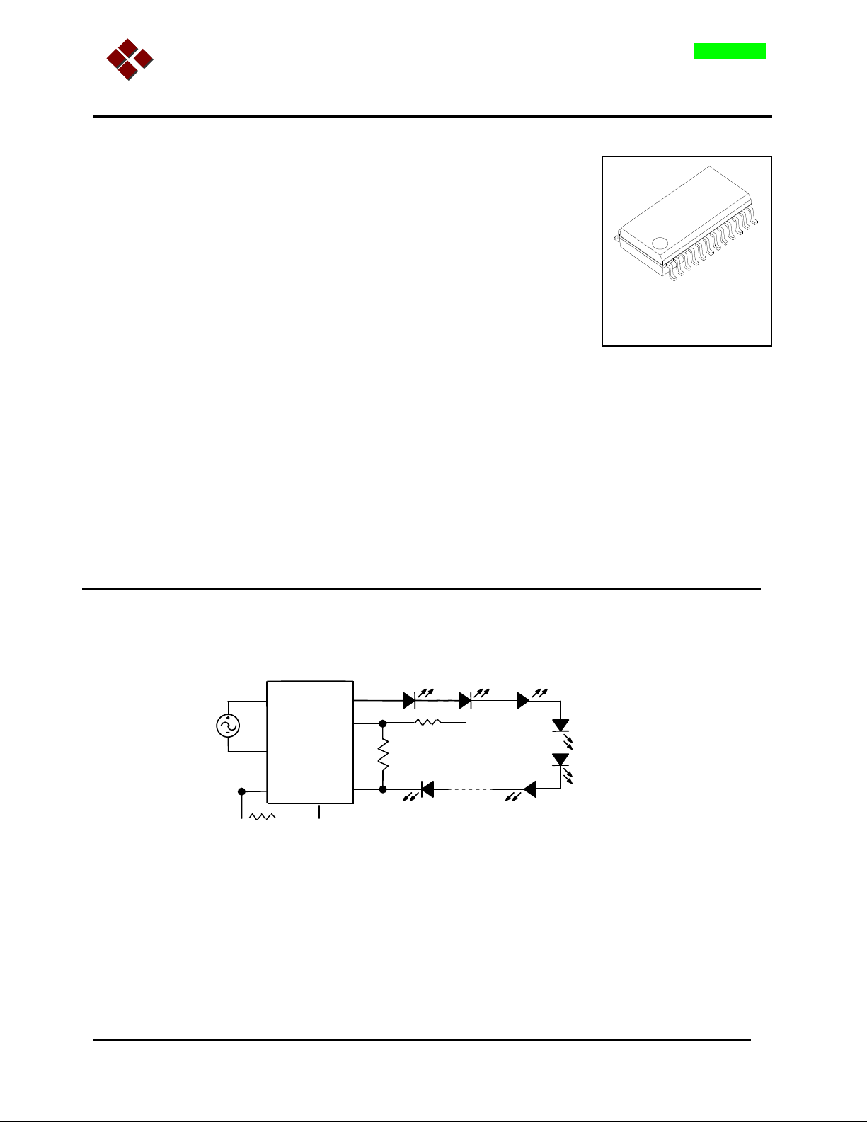
Typical Application Circuit
110VAC
1
24
10
REF
PC
Note: There is no pin being connected to earth ground.
OUT +
DA
OUT -
6
9
7
1
11
: Voltage
OUT
Pin 9 and Pin 11.
ÓMacroblock, Inc. 2003
Floor 6-4, No. 18, Pu-Ting Rd., Hsinchu, Taiwan 30077, ROC.
TEL: +886-3-579-0068, FAX: +886-3-579-7534 E-mail: info@mblock.com.tw
Page 2
2 3 4 5 6 7 10 11 12
8 14
17 18 19 20 21 22 23 24
NC
MBI6001-V1.0i Transformerless AC/DC Constant Current Driver
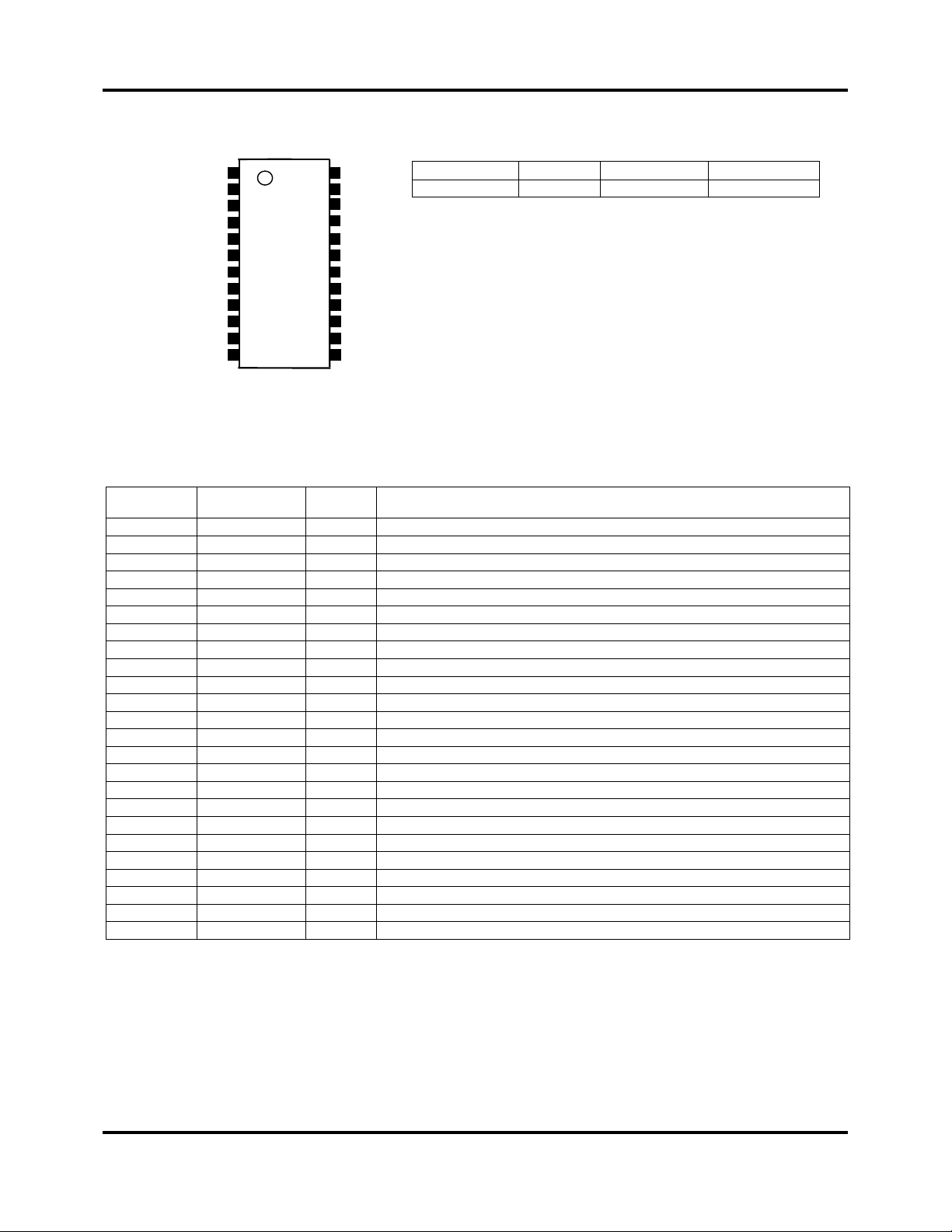
Pin Configuration
AC IN ~
NC
HV
PC
OUT+
REF
OUT-
1
HV
HV
DA
NC
9
MBI6001N1D
16
15
13
AC IN ~
NC
HV
NC
HV
HV
NC
REF
REF
NC
HV
HV
Ordering Information
Part Blink VAC Range Package-Pin
MBI6001N1D
NA 100V ~ 120V
Pin Description (SOP24)
Pin Name I/O Function
1 AC IN ~ In AC voltage input node1.
2 NC
3 HV
4 HV
5 HV
6 PC In Peak current adjust.
7 DA In Duty adjust.
8 NC - No connection.
9 OUT+ Out Connected to LED anode (+).
10 REF
11 OUT- Out Connected to LED cathode (-).
12 NC
13 HV
14 HV
15 NC - No connection.
16 REF
17 REF
18 NC
19 HV
20 HV
21 NC
22 HV
23 NC
24 AC IN ~ In AC voltage input node2.
Note 1: These Pins should be kept away from touching by hands. (High voltage 110VAC)
-
No connection.
-
No connection.
-
No connection.
-
No connection.
-
Internal reference voltage low.
-
No connection.
-
No connection.
-
No connection.
-
Internal reference voltage low.
-
Internal reference voltage low.
-
No connection.
-
No connection.
-
No connection.
-
No connection.
-
No connection.
-
No connection.
SOP-24
- 2 -
Page 3

MBI6001-V1.0i Transformerless AC/DC Constant Current Driver
Environmental Specification
Operation Temperature Range ---- −20°C to 50°C (LEDs are set in the temperature range:-20℃ to 70℃)
Storage Temperature Range ----- −40°C to 150°C
Cooling--------------------------------- Free Air or Thermally Conductive Adhesive
Absolute Maximum Ratings
AC Input Voltage----------------- 400V, transient
Power Dissipation ------------------------- 1.5 W
Junction Temperature ---------------------120°C
Electrical Characteristics
(VAC= 110V, Ta = 25°C, unless otherwise noted)
PARAMETER SYMBOL MIN TYP MAX
AC Input Voltage V
Output Voltage V
Output Current I
100 110 120 V rms See Applications Information
AC
8 - 60 V
OUT
18 mA See Applications Information
OUT
UNIT
S
NOTE
- 2 -
Page 4

MBI6001-V1.0i Transformerless AC/DC Constant Current Driver
Applications Information
Output Current - I
OUT
With a selected resistor R1 being connected between DA and OUT- (refer to Typical Application
Circuit), a constant output current I
However, I
used and less than 60V, I
Fig. 1- I
26
22
18
(mA)
OUT
I
14
10
will vary with V
OUT
vs. V
OUT
915304560
(@ 110 VAC, Ta= 25 °C)
OUT
OUT
will vary within the range of ± 15%. (see Fig. 1)
OUT
can be produced.
OUT
. While V
is changed due to different number of LEDs being
OUT
V
(V)
OUT
Surface Temperature vs. V
The temperature on the surface of package will be around 60 °C when V
Temperature will rise up while V
OUT
is getting larger. (see Fig. 2)
OUT
is smaller than 60V.
OUT
Fig. 2- Temp. vs. V
(@ 110 VAC, Ta= 25 °C)
OUT
100
80
60
TEMP (°C)
40
20
915304560
V
(V)
OUT
- 3 -
Page 5

MBI6001-V1.0i Transformerless AC/DC Constant Current Driver
Line Regulation
I
will vary obviously with AC Input voltage. For instance, at V
OUT
20% while input voltage varies from 110 VAC to 100 VAC, but decrease 15% while input
voltage varies from 110 VAC to 120 VAC. For input voltage is usually staying at lower than
100VAC, it is recommended to lower down the V
up very quickly and the surface temperature of package will be getting higher than 90°C.
in the application. Otherwise, I
OUT
LEDs Selection Consideration
MBI6001 provides constant average output current to drive LEDs. The output to LEDs is
actually a train of current pulses. Their peak value can be adjusted by a resistor R2 which
connects from PC to V-. (refer to Typical Application Circuit) It is recommended to select LEDs
with higher peak forward current IF(peak).
Cautions
MBI6001 is directly power supplied by 110V AC. There are several pins with high AC voltage.
Please don’t touch any pin by hand(s) after voltage in. Also, it is important to keep preventing
pins from short-circuit.
= 50 V, I
OUT
will increase
OUT
will rise
OUT
- 4 -
Page 6

MBI6001-V1.0i Transformerless AC/DC Constant Current Driver
Outline Drawings
SOP24 – P – 300 – 1.27
- 5 -
 Loading...