

Page 1
Sept. 1995
Edition 2.0a
DATA SHEET
MB1508
SERIAL INPUT PLL FREQUENCY SYNTHESIZER
SERIAL INPUT PLL
FREQUENCY SYNTHESIZER
ON CHIP 2.5 GHz PRESCALER
DESCRIPTION
The Fujitsu MB1508 with an on chip 2.5 GHz dual modulus prescaler is a serial input
PLL (Phase Locked Loop) frequency synthesizer with pulse swallow function. It is
well suited for BS tuner, CATV system, and TV tuner applications.
It operates with a supply voltage of 5.0V typ. and dissipates 16mA typ. of current
realized through the use of Fujitsu’s unique U-ESBIC Bi-CMOS technology.
FEATURES
• Power supply voltage: VCC = 4.5 to 5.5V
• High operating frequency: f
= 2.5 GHz (P
IN
= –4dBm)
IN
• 2.5 GHz dual modulus prescaler: P = 256/272, 512/528
• Low supply current: I
= 16mA typ.
CC
• Programmable reference divider consisting of:
Binary 2-bit programmable reference counter (R = 256, 512, 1024, 2048)
• Programmable divider consisting of:
Binary 5-bit swallow counter (A = 0 to 31)
Binary 12-bit programmable counter (N = 32 to 4095)
• Wide operating temperature: –40C to +85C
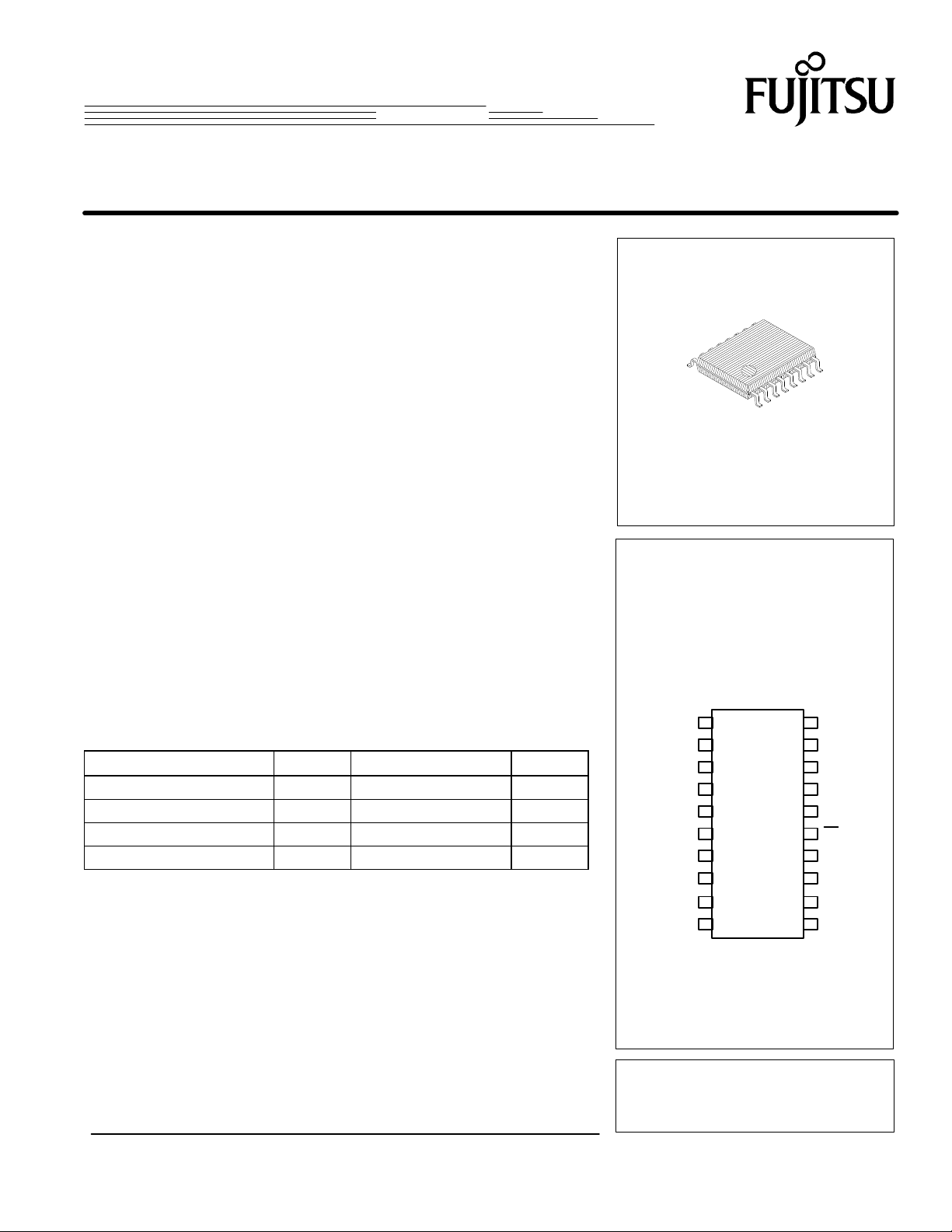
• Plastic 20-pin Flat Package (Suffix: —PF)
ABSOLUTE MAXIMUM RATINGS (See NOTE)
RatIng Symbol Value Unit
Power Supply Voltage V
Output Voltage V
Output Current I
Storage Temperature T
NOTE: Permanent device damage may occur if the above Absolute Maximum RatIngs are exceed-
ed.Functional operation should be restricted to the condItions as detailed in the operational
sections of this data sheet. Exposure to absolute maximum rating conditions for extended periods
may affect device reliability.
CC
O
O
STG
–0.5 to +7.0 V
–0.5 to VCC +0.5 V
± 10 mA
–55 to +125 C
Plastic Package
FPT–20P–M01
Pin Assignment
(TOP VIEW)
FC 1 20 LD
LE 2 19
Data 3 18 VCC2
Clock 4 17 fIN
VCC1 5 16 GND2
IN 615fIN
OSC
OSCOUT 7 14 BC1
GND 8 13 BC2
D0
D0
9 12 BC3
1
10 11 BC4
2
fOUT
This device contains circuitry to protect the inputs against
damage due to high static voltages or electric fields. However,
it is advised that normal precautions be taken to avoid
application of any voltage higher than maximum rated voltages
to this high impedance circuit.
Page 2
MB1508
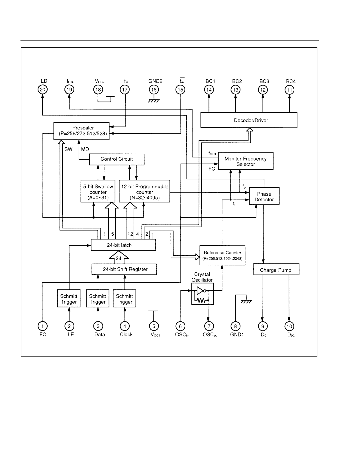
MB1508 Block Diagram
2
Page 3
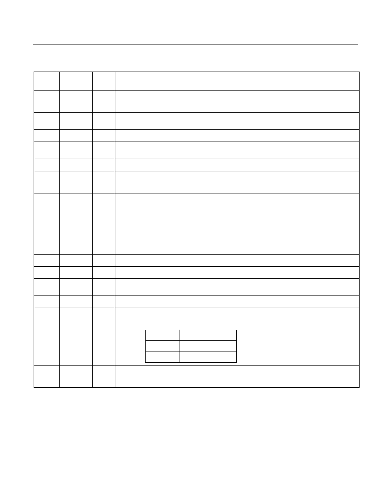
PIN DESCRIPTION
MB1508
Pin
No.
1 FC I
2 LE I
Pin
Name
I/O Description
Phase select input pin of the phase detector. This pin involves an internal pull up resistor.
When this pin is low, characteristics of the charge pump and phase detector can be reversed.
This input also selects f
Load enable input pin. This pin involves a schmitt trigger circuit.
When this pin is high, the data stored in the shift register is transferred into the latch.
pin output level, either fr or fp. Please see page 6.
OUT
3 Data I Serial data of binary code input pin. This pin involves a schmitt trigger circuit.
4 Clock I
5 V
6
7
OSC
OSC
CC1
IN
OUT
— PLL power supply voltage input pin.
O
Clock input for 24-bit shift register. This pin involves a schmitt trigger circuit.
On rising edge of the clock shifts one bit of data into the shift registers.
Oscillator input pin.
I
Oscillator output pin.
A crystal is connected between OSC
pin and OSC
IN
OUT
pin.
8 GND1 — PLL ground pin.
9
10
11
12
13
14
D
O1
D
O2
BC4
BC3
BC2
BC1
O
O
O
O
O
Charge pump output pins.
Phase characteristics can be reversed depending upon FC pin input level.
Band switching output pins. (Open-collector output)
Output is controlled by a band bit data, individually.
BCX—bit = H : BCX output transistor is ON.
BCX—bit = L : BCX output transistor is OFF.
(X = 1 to 4)
15 fin I Complementary input pin of fin. Please connect to GND through a capacitor.
16 GND2 — Prescaler ground pin.
17 f
18 V
19 f
in
CC2
OUT
20 LD O
— Prescaler power supply voltage input pin.
O
Prescaler input pin.
I
This signal is AC coupled.
Monitor pin of the phase detector input.
f
pin outputs either of the programmable reference divider output frequency fr or programmable divider
OUT
output frequency f
Phase detector output pin.
Normally this pin outputs high. While the phase difference between f
outputs low.
depending upon the FC pin input level.
p
FC Pin f
Hf
Lf
output signal
out
r
p
and fp exists, this pin
r
3
Page 4
MB1508
e
FUNCTIONAL DESCRIPTIONS
DIVIDE RATIO SETTING
Divide ratio can be set using the following equation:
f
= [(P x N)+ (16 x A] x f
vco
: Output frequency of external voltage controlled oscillator (VCO)
f
vco
P: Preset divide ratio of an internal dual modulus prescaler (256 or 512)
N: Preset divide ratio of binary 12-bit programmable counter (32 to 4095)
A: Preset divide ratio of binary 5-bit swallow counter (0 to 31)
: Reference oscillator frequency
f
osc
R: Preset divide ratio of reference counter (256, 512, 1024, 2048)
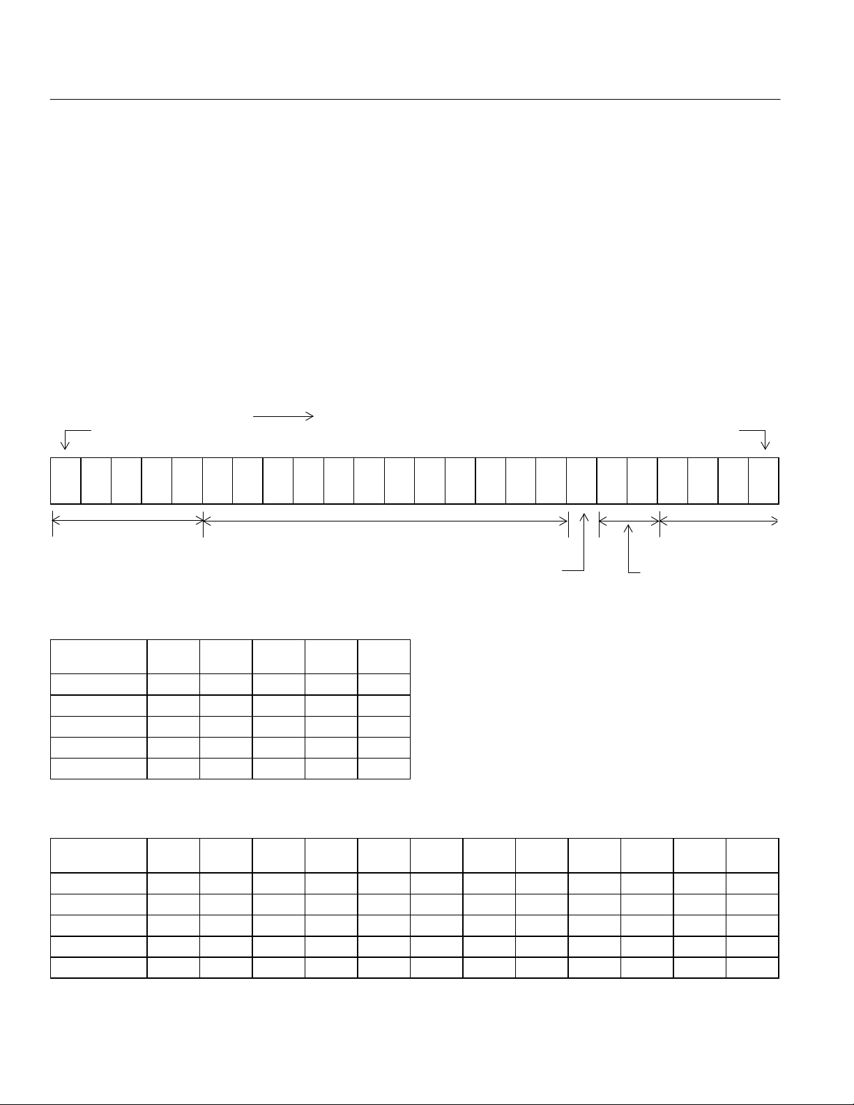
SERIAL DATA INPUT
On rising edge of clock shifts one bit of the data into the shift register.
When the load enable is high, the data stored in the shift register is transferred to the latch.
24 bit of serial data format is shown below.
LSB
osc
÷ R
Data Input Flow
MSB
A1A2A3A4A5N1N2N3N4N5N6N7N8N
Divide ratio of swallow
counter setting bit
Divide ratio of programmable
counter setting bit
prescaler setting bit
N
1
9
0
Divide ratio of
N
N
11
1
2
SWR1R
B
C
2
4
Divide ratio of referenc
counter setting bit
5-BIT SWALLOW COUNTER DIVIDE RATIO (A1 to A5)
Divide Ratio
A
0 0 0 0 0 0
1 0 0 0 0 1
2 0 0 0 1 0
31 1 1 1 1 1
A
5
A
4
A
3
A
2
A
1
12-BIT PROGRAMMABLE COUNTER DIVIDE RATIO (N1 to N12)
Divide
Ratio
32 0 0 0 0 0 0 1 0 0 0 0 0
33 0 0 0 0 0 0 1 0 0 0 0 1
34 0 0 0 0 0 0 1 0 0 0 1 0
4095 1 1 1 1 1 1 1 1 1 1 1 1
12
N
N
11
10
N
N
9
N
8
N
7
N
6
N
5
N
4
N
3
B
B
C
C
3
2
Band switch
setting bit
N
2
B
C
1
N
1
4
Page 5

FUNCTIONAL DESCRIPTIONS
REFERENCE COUNTER DIVIDE RATIO (R1 to R2)
MB1508
Divide Ratio
R
256 o o
512 0 1
1024 1 0
2048 1 1
R
2
R
1
Prescaler divide ratio (SW)
When divide ratio of prescaler setting bit is high, divide ratio of 256/272 is selected.
When divide ratio of prescaler setting bit is low, divide ratio of 512/528 is selected.
Band Switch Setting (BC1 to BC4)
When band switch setting bit is high, output is ON.
When band switch setting bit is low, output is OFF.
5
Page 6
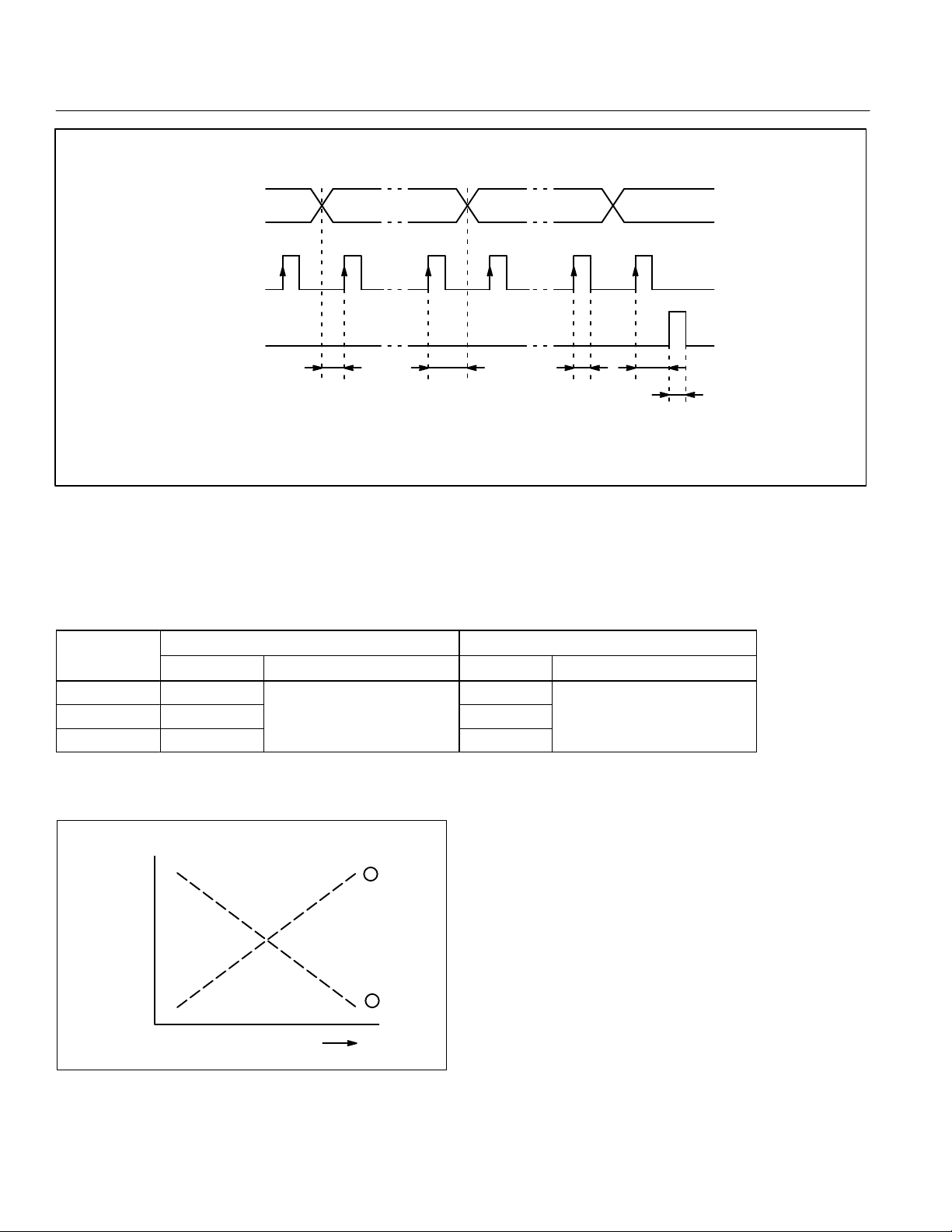
MB1508
O
O
p
p
Serial Data Input Timing
Data
S18 =
MSB
(SW) (
S17 S10 S9
(S14) (S8) (S7) (S1) (C: Control bit)
∗1)
S1 =
LSB
C: Control bit
Clock
LE
t1 t2 t3
t4
t5
∗1 : Bits enclosed in parentheses are used when the divide ratio of the programmable reference divider is selected.
Note: One bit of data is shifted into the shift register on the rising edge of the clock.
NOTES: On rising edge of the clock shifts one bit of data into the shift register.
When LE is high, the data stored in the shift register is transferred into the latch.
PHASE DETECTOR CHARACTERISTICS
FC pin selects the phase of the phase detector. Phase characteristics (charge pump output) can be reversed depending upon the FC pin
input level. Monitor pin (f
.
D
fr > f
p
f
= f
r
p
fr < f
p
) output level is selected by FC pin input level as well
OUT
FC=H or open FC=L
o1,
D
o2
H
L
Z
reference divider output
f
OUT
utputs programmable
frequency fr.
D
D
O,
02
L
Z
H
f
OUT
utputs programmable
divider output
frequency fp.
Note: Z = (High impedance)
VCO
output
frequency
6
LPF input voltage
1
VCO CHARACTERISTICS
Depending upon VCO polarity,
FC pin should be set accordingly:
— When VCO polarity are like
FC should be set High or open.
— When VCO polarity are like
2
FC should be set Low.
Page 7
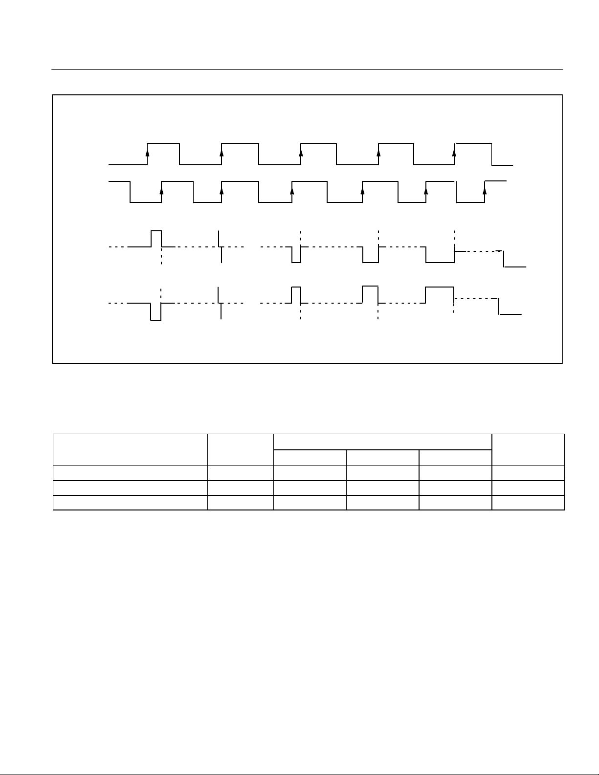
PHASE DETECTOR WAVEFORM
fr
fp
MB1508
(FC =H)
D
D
01,
02
H
Z
L
(FC –L)
D
D
01,
02
Z
fr > fp fr = fp fr < fp fr < fp fr < fp
NOTES: Phase difference detection range: –2π to +2π
Spike shape depends on charge pump characteristics.
The spike is output to diminish dead band.
RECOMMENDED OPERATING CONDITIONS
Parameter Symbol
Power Supply Voltage V
Input Voltage V
Operating Temperature T
CC
Min Typ Max
4.5 5.0 5.5 V
I
A
GND — V
–40 — +85 C
Value
CC
Unit
V
Handling Precautions
• This device should be transported and stored in anti-static containers.
• This is a static-sensitive device; take proper anti-ESD precautions. Ensure that personnel and equipment are properly grounded.
Cover workbenches with grounded conductive mats.
• Always turn the power supply off before inserting or removing the device from its socket.
• Protect leads with a conductive sheet when handling or transporting PC boards with devices.
7
Page 8
MB1508
in
fin
Except f
p
O
p
O
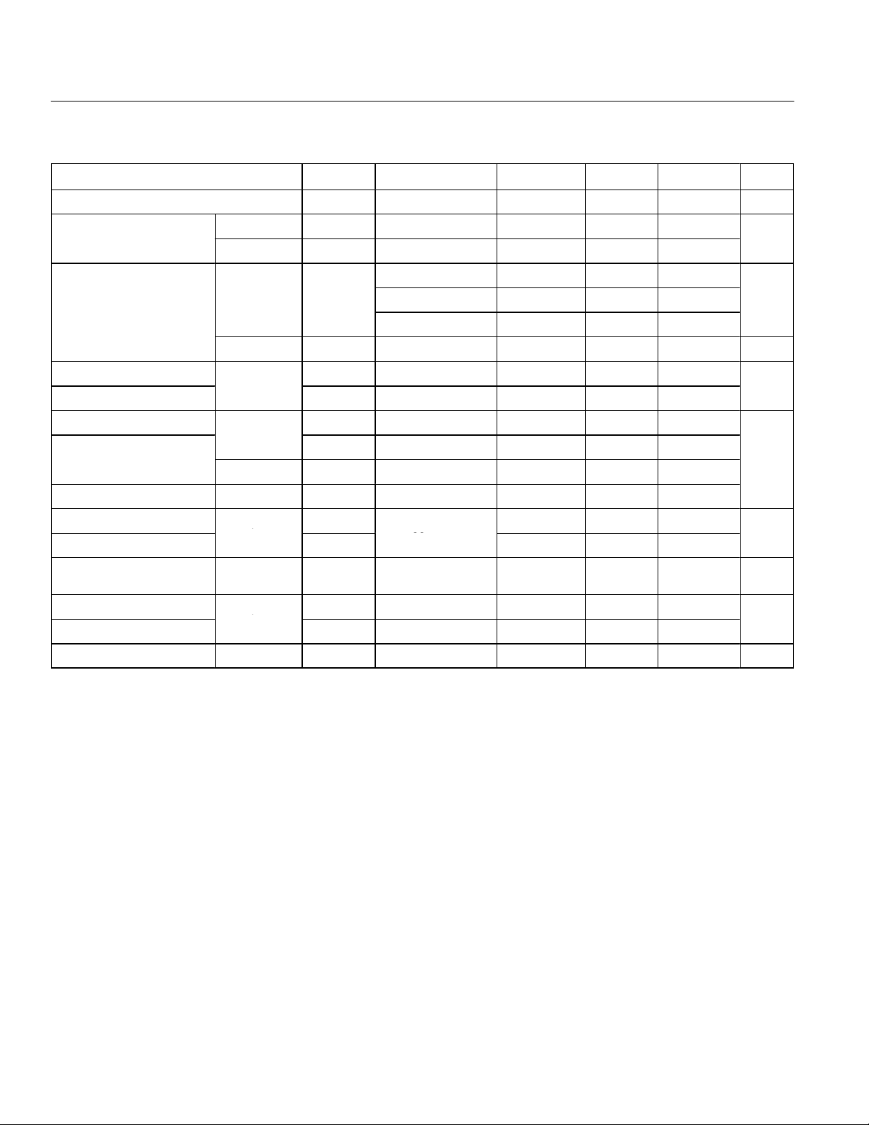
ELECTRICAL CHARACTERISTICS
Parameter Symbol Condition Min Typ Max Unit
Power Supply Current I
f
Operating Frequency
Input Sensitivity
High-level Input Voltage
Low-level Input Voltage
High-level Input Current
in
OSC
IN
f
in
OSC
IN
Except f
and OSC
Data
Clock
LE
f
V
in
IN
Low-level Input Current
FC I
Input Current OSC
High-level Output Voltage
Low-level Output Voltage
High Impedance
Cutoff Current
High-level Output Current
Low-level Output Current
Except D
and
BC1 to BC4
DO1, D
BC1 to BC4
Except D
and
BC1 to BC4
IN
O
02
O
I
V
I
Withstand Output Voltage BC1 to BC4 V
CC
f
OSC
P
OSC
V
V
I
IH
I
ILFC
OSC
OH
V
OL
OFF
I
OH
I
OL
Note 1 — 16.0 — mA
in
Note2 10 — 2500
MHz
— — 4 10
2300 to 2500MHz –4 — 6
fin
1900 to 2300MHz –7 — 6 dBm
10 to 1900MHz –10 — 6
— 0.5 — — V
IH
IL
— VCCx 0.7+0.4 — —
— — — VCCx0.3–0.4
PP
V
— — 1.0 —
IL
— — –1.0 —
µA
— — –60 —
— — +50 —
4.4 — —
VCC = 5.0 V
V
— — 0.4
— — — 1.1 µA
— –1.0 — —
mA
— 1.0 — —
B
— — — 12 V
NOTE: 1: f in = 2.5GHz, OSCIN=4.0MHz, Vcc=5.0V. Inputs are grounded and outputs are open.
2: AC coupling. Minimum operating frequency is measured with a capacitor 1000pF.
8
Page 9
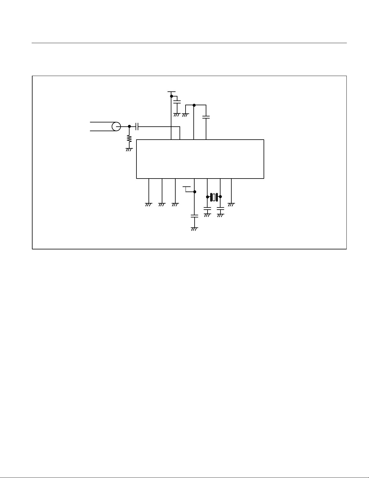
TEST CIRCUIT
Prescaler Input Sensitivity
MB1508
1000 p
P · G
50
Ω
1000 p
20 19 18 17 16 15 14 13 12 11
MB1508
1 2 3 4 5 6 7 8 9 10
0.1
µ
0.1 µ
9
Page 10
MB1508
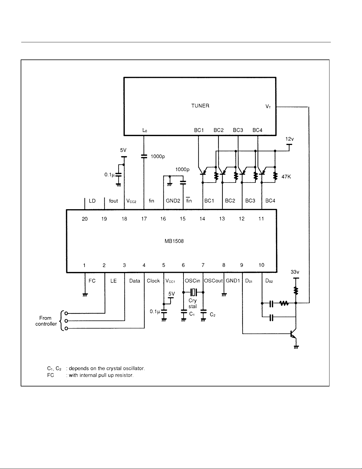
MB1508 APPLICATION CIRCUIT
10
Page 11
PACKAGE DIMENSIONS
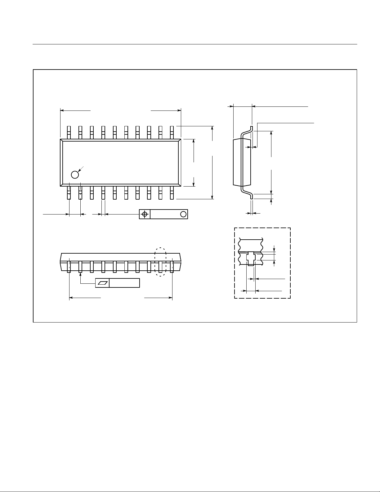
20–Lead Plastic Flat Package
(Case No.: FPT–20P–M01)
MB1508
.500
INDEX
+.010
–.008
.018
(0.45
.450(1 1.43) REF
+0.25
(12.70 )
–0.20
±.004
±0.10)
.004(0.10)
∅.005(0.13) M
“A”
.209±.012
(5.30
±0.30)
.307±.016
(7.80
±0.40)
.089(2.25) MAX
(MOUNTING HEIGHT)
.002(0.05) MIN
(STAND OFF HEIGHT)
+.016
.268 (6.80 )
–.008
+.002
.006 (0.15 )
–.001
Details of “A” part
.008(0.20)
.020(0.50)
.007(0.18)
MAX
.027(0.68)
MAX
.020
(0.50
+0.40
–0.20
±.008
±0.20)
+0.05
–0.02
1991 FUJITSU LIMITED F20003S-5C
Dimensions in
inches (millimeters)
11
Page 12

MB1508
All Rights Reserved.
Circuit diagrams utilizing Fujitsu products are included as a means of illustrating
typical semiconductor applications. Complete Information sufficient for construction
purposes is not necessarily given.
The information contained in this document has been carefully checked and is
believed to be reliable. However, Fujitsu assumes no responsibility for inaccuracies.
The information contained in this document does not convey any license under the
copyrights, patent rights or trademarks claimed and owned by Fujitsu.
Fujitsu reserves the right to change products or specifications without notice.
No part of this publication may be copied or reproduced in any form or by any means,
or transferred to any third party without prior written consent of Fujitsu.
12
Page 13

FUJITSU LIMITED
For further information, please contact:
Japan
FUJITSU LIMITED
Semiconductor Marketing
Furukawa Sogo Bldg.
6-1, Marunouchi 2-chome
Chiyoda-ku, Tokyo 100
Japan
Tel: (03) 3216-3211
Telex: 781-2224361
FAX: (03) 3216-9771
North and South America
FUJITSU MICROELECTRONICS, INC.
Semiconductor Division
3545 North First Street
San Jose, CA 95134-1804 USA
Tel: (408) 922-9000
FAX: (408) 432-9044
Europe
FUJITSU MIKROELEKTRONIK GmbH
Arabella Centre 9.OG
Lyoner Strasse 44-48
D-6000 Frankfurt 71
F.R. Germany
Tel: (069) 66320
Telex: 411963
FAX: (069) 6632122
MB1508
Asia
FUJITSU MICROELECTRONICS ASIA PTE LIMITED
51 Bras Basah Road
Plaza by the Park
#06-04/07
Singapore 0718
Tel: 336-1600
Telex: 55373
FAX: 336-1609
1991 FUJITSU LIMITED IC-07229-2-91-DS
13
 Loading...