

Page 1

Click here to ask about the production status of specific part numbers.
MAX78000FTHR
Application Platform
General Description
The MAX78000FTHR is a rapid development platform to
help engineers quickly implement ultra low-power, artificial intelligence (AI) solutions using the MAX78000 Arm
Cortex®-M4F processor with an integrated Convolutional
Neural Network accelerator. The board also includes the
MAX20303 PMIC for battery and power management.
The form factor is 0.9in x 2.6in dual-row header footprint
that is compatible with Adafruit Feather Wing peripheral expansion boards. The board includes a variety of
peripherals, such as a CMOS VGA image sensor, digital
microphone, low-power stereo audio CODEC, 1MB QSPI
SRAM, micro SD card connector, RGB indicator LED,
and pushbutton. The MAX78000FTHR provides a poweroptimized flexible platform for quick proof-of-concepts and
early software development to enhance time to market.
Go to https://www.maximintegrated.com/en/products/
MAX78000FTHR to get started developing with this board.
Ordering Information appears at end of data sheet.
®
Evaluates: MAX78000
Features
● MAX78000 Microcontroller
• Dual Core: Arm Cortex-M4 Processor with FPU,
100MHz, RISC-V Coprocessor, 60MHz
• 512KB Flash Memory
• 128KB SRAM
• 16KB Cache
• Convolutional Neural Network Accelerator
• 12-Bit Parallel Camera Interface
• MAX20303 Wearable PMIC with Fuel Gauge
• Charge from USB
• On-Board DAPLink Debug and Programming
Interface for Arm Cortex-M4 processor with FPU
• Breadboard Compatible Headers
• Micro USB Connector
• Micro SD Card Connector
● Integrated Peripherals
• RGB Indicator LED
• User Pushbutton
• CMOS VGA Image Sensor
• Low-Power Stereo Audio CODEC
• Digital Microphone
• SWD Debugger
• Virtual UART Console
• 10-Pin Cortex Debug Header for RISC-V
Coprocessor
Arm and Cortex are registered trademarks of Arm Limited
(or its subsidiaries) in the US and/or elsewhere.
319-100628; Rev 0; 11/20
Page 2

MAX78000FTHR
Application Platform
Evaluates: MAX78000
Quick Start
Apply power to the MAX78000FTHR using the USB
cable. The pre-programmed 'Audio Keyword Spotting'
demo will begin to execute.
The RGB LED (D2) will turn on green, indicating that
the demo is running. The on-board microphone starts
listening for the keyword GO. When the keyword GO is
detected, RGB LED (D2) will turn on yellow. In this mode,
when one of nine keywords is detected, the RGB LED
(D1) starts to blink blue one to nine times based on the
number detected by the convolutional neural network.
The STOP command exits number keyword detection,
and the RGB LED (D2) turns on green again, and RGB
LED (D1) turns off.
PMIC and Battery Charger
The MAX20303 wearable PMIC powers the
MAX78000FTHR board and is also capable of charging a
Li-Ion battery (not included). The MAX20303 has an internal MOSFET that connects the battery to system output
when no voltage source is available on the charge input
(USB). When an external source is detected at the charge
input (USB), this switch opens and the system output is
powered from the input source through the input current
limiter. The system output to battery switch also prevents
the system output voltage from falling below battery voltage when the system load exceeds the input current limit.
The smart power selector unit inside the PMIC seamlessly
distributes power from the charge input (USB) to the battery and system output. With both the USB and battery
connected, the smart power switch's basic functions are:
● When the system load requirements are less than
the input current limit, the battery is charged with
residual power from the input.
● When the system load requirements exceed the input
current limit, the battery supplies supplemental current to the load.
● When the battery is connected, and there is no exter-
nal power input (USB), the system is powered from
the battery.
● When the MAX20303 thermal limits are reached, the
charger does not shut down, but attempts to limit a
temperature increase by reducing the input current
from charge input. In this condition, the system load
has priority over the charger current, so the input current is first reduced by lowering the charge current. If
the junction temperature continues to rise and reaches the maximum operating limit, no input current is
drawn from the charge input and the battery powers
the entire system load.
The USB charge current is set to 51mA. This allows charging from both powered and unpowered USB hubs with no
port communication required. Refer to the MAX20303
data sheet and the data sheet for your battery to ensure
compatibility.
Programming and Debugging
The MAX32625 microcontroller on the board is preprogrammed with DAPLink firmware. It allows debugging
and programming of the MAX78000 Arm core over USB.
A standard 10-pin JTAG header J1 allows debugging and
programming the RISC-V core of the MAX78000.
Pushbuttons
There are five pushbuttons on the MAX78000FTHR
board:
SW1 User-programmable function button connected to
the MAX78000 Port 0.2 through a debouncer IC.
SW2 User-programmable function button connected to
the MAX78000 Port 1.7 through a debouncer IC.
SW3 PMIC Power Button
When the board is in a powered-on state, pressing this button for 12 seconds performs a hard
power-down.
When the board is in a powered-off state, pressing
this button powers on the board.
This button can also be read by the MAX78000
firmware, PMIC_PFN2 signal connected to the
Port 3.1 is a buffered input of the button status.
When the button is pressed, this signal goes to a
logic-low state.
SW4 Resets the MAX78000 through RSTN input of the
MAX78000.
SW5 DAPLink adapter button. Keep this button
pressed while applying power to the board to
put the MAX32625 DAPLink adapter on board
to MAINTENANCE mode for DAPLink firmware
updates.
LEDs
There are three RGB LEDs on the MAX78000FTHR
board.
www.maximintegrated.com
Maxim Integrated
│
2
Page 3

MAX78000FTHR
Application Platform
Evaluates: MAX78000
D1 Connected to the MAX78000 GPIO ports. This
LED can be controlled by user firmware.
Port 2.0 : Red color
Port 2.1 : Green color
Port 2.2 : Blue color
D2 Connected to MAX20303 PMIC LEDx outputs.
These LEDs can be controlled through I2C commands. They also can be configured as charge
status indicators by issuing I2C commands.
D3 DAPLink adapter MAX32625 status LED.
Controlled by the DAPLink adapter and cannot be
used as a user LED.
Figure 1. MAX78000FTHR Pinout Diagram
www.maximintegrated.com
Maxim Integrated
│
3
Page 4

MAX78000FTHR
Application Platform
Evaluates: MAX78000
Figure 2. MAX78000FTHR Top Side Components
www.maximintegrated.com
Maxim Integrated
│
4
Page 5

MAX78000FTHR
Application Platform
Evaluates: MAX78000
Figure 3. MAX78000FTHR Bottom Side Components
www.maximintegrated.com
Maxim Integrated
│
5
Page 6
MAX78000FTHR
Evaluates: MAX78000
Application Platform
Expansion Headers
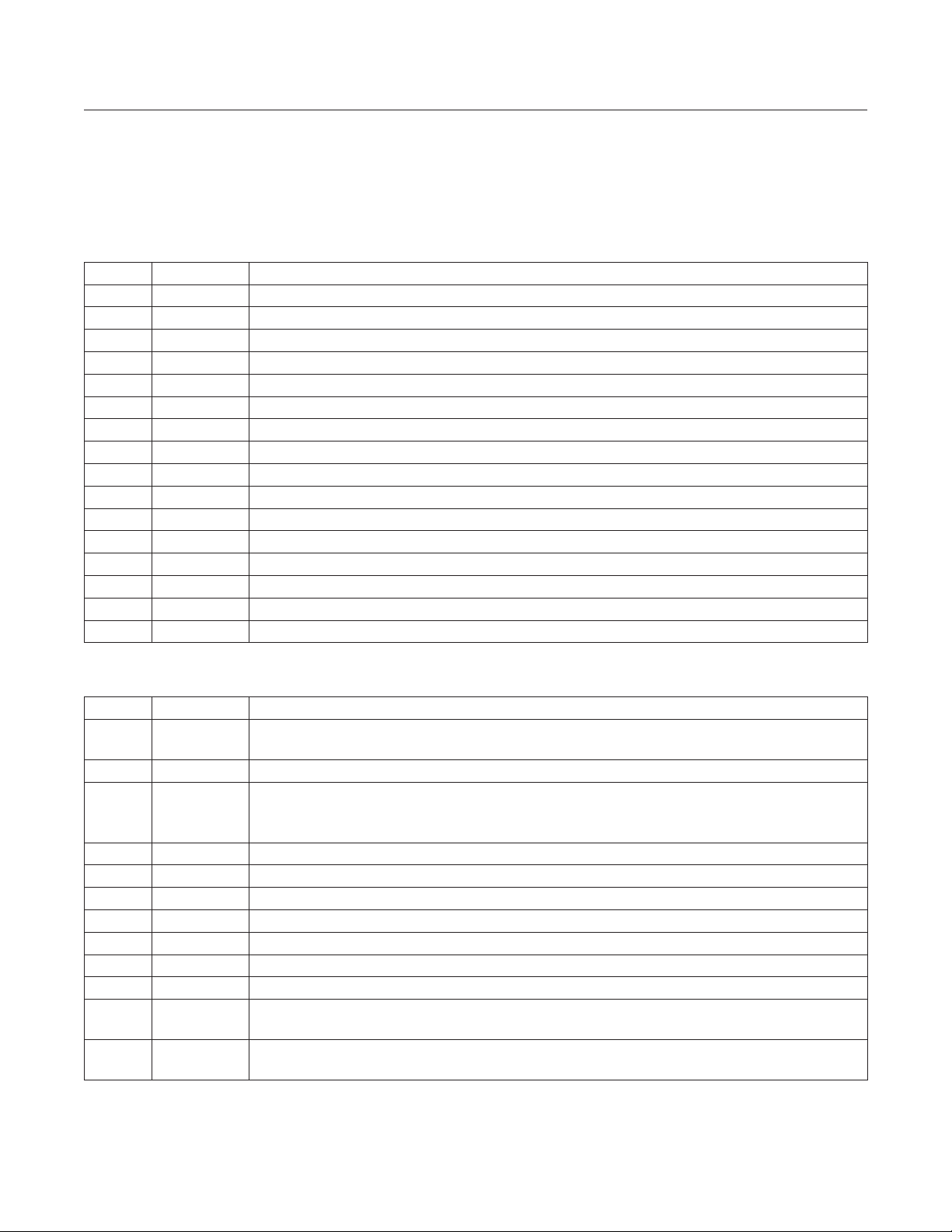
Table 1. J8 Pinout
PIN NAME DESCRIPTION
1 RST Master Reset Signal
2 3V3 3.3V Output. Typically used to provide 3.3V to peripherals connected to the expansion headers
3 1V8 1.8V Output. Typically used to provide 1.8V to peripherals connected to the expansion headers
4 GND Ground
5 P2_3 GPIO or Analog Input (AIN3 channel)
6 P2_4 GPIO or Analog Input (AIN4 channel)
7 P1_1 GPIO or UART2 Tx signal
8 P1_0 GPIO or UART2 Rx signal
9 MPC1 GPIO controlled by PMIC through I2C interface. Open drain or push-pull programmable
10 MPC2 GPIO controlled by PMIC through I2C interface. Open drain or push-pull programmable
11 P0_7 GPIO or QSPI0 clock signal. Shared with SD card and on-board QSPI SRAM
12 P0_5 GPIO or QSPI0 MOSI signal. Shared with SD card and on-board QSPI SRAM
13 P0_6 GPIO or QSPI0 MISO signal. Shared with SD card and on-board QSPI SRAM
14 P2_6 GPIO or LPUART Rx signal
15 P2_7 GPIO or LPUART Tx signal
16 GND Ground
Table 2. J4 Pinout
PIN NAME DESCRIPTION
1 SYS
2 PWR Turns o the PMIC if shorted to Ground for 13 seconds. Hard power-down button.
3 VBUS
4 P1_6 GPIO
5 MPC3 GPIO controlled by PMIC through the I2C interface. Open drain or push-pull programmable.
6 P0_9 GPIO or QSPI0 SDIO3 signal. Shared with SD card and on-board QSPI SRAM.
7 P0_8 GPIO or QSPI0 SDIO2 signal. Shared with SD Card and on-board QSPI SRAM.
8 P0_11 GPIO or QSPI0 slave select signal.
9 P0_19 GPIO
10 P3_1 GPIO or Wake-up signal. This pin is 3.3V only.
11 P0_16
12 P0_17
SYS Switched Connection to the Battery. This is the primary system power supply and automatically
switches between the battery voltage and the USB supply when available.
USB VBUS Signal. This can be used as a 5V supply when connected to USB. This pin can also be
used as an input to power the board, but this should only be done when not using the USB connector
since there is no circuitry to prevent current from owing back into the USB connector.
GPIO or I2C1 SCL signal. An on-board level shifter allows selecting 1.8V or 3.3V operation through
R15 or R20 resistors. Do not populate both.
GPIO or I2C1 SDA signal. An on-board level shifter allows selecting 1.8V or 3.3V operation through
R15 or R20 resistors. Do not populate both.
www.maximintegrated.com
Maxim Integrated
│
6
Page 7
MAX78000FTHR
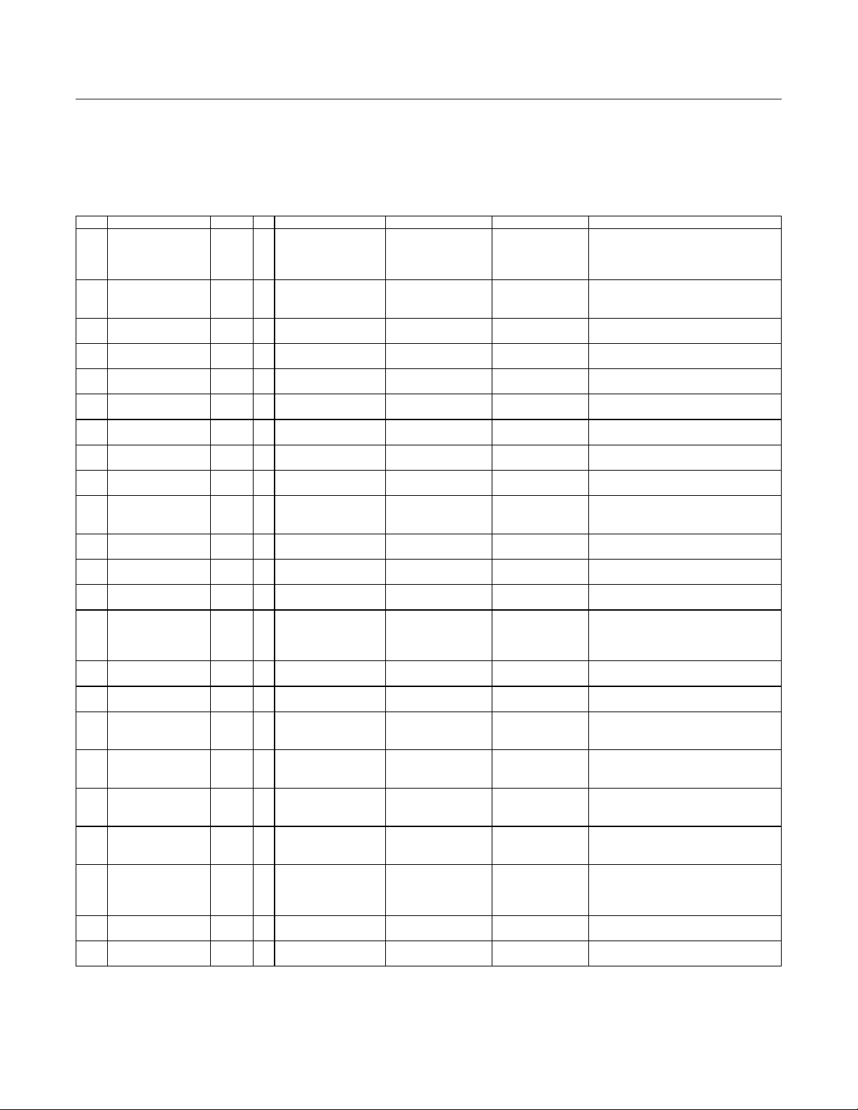
ITEM REF_DES DNI/DNP QTY MFG PART # MANUFACTURER VALUE DESCRIPTION
C1, C3, C6, C7, C9, C10,
C69, C70, C73, C74
C2, C17, C18, C32, C35,
C55, C58
GMK107BJ105KA;
C1608X5R1V105K080AB
CAP; SMT (0603); 1.0UF; 10%; 35V;
X5R; CERAMIC
CAP; SMT (0603); 0.1UF; 10%; 25V;
X8R; CERAMIC
CAP; SMT (0805); 47UF; 20%; 10V;
X5R; CERAMIC
CAP; SMT (0603); 22UF; 20%; 16V;
X5R; CERAMIC
CAP; SMT (0402); 3300PF; 10%;
50V; X7R; CERAMIC
CAP; SMT (0201); 2.2UF; 10%; 10V;
X5R; CERAMIC
C22, C23, C27, C30,
C31, C33, C36
CAP; SMT (0201); 1UF; 20%; 10V;
X5R; CERAMIC
C25, C26, C59, C61,
C72, C75, C76
CAP; SMT (0201); 220PF; 10%; 25V;
X7R; CERAMIC
CAP; SMT (1206); 220UF; 20%; 6.3V;
X5R; CERAMIC
CAP; SMT (0201); 0.1UF; 10%; 10V;
X5R; CERAMIC
C1608X5R1E225K;
GRM188R61E225KA12
C1608X5R1E475K080AC;
GRM188R61E475KE11
CAP; SMT (0603); 4.7UF; 10%; 25V;
X5R; CERAMIC
CONNECTOR; FEMALE; SMT;
47346 SERIES; RIGHT ANGLE; 5PINS
LUMEX
INC
DIODE; LED; SML; FULL COLOR;
SMT;VF=2.95V; IF=0.1A
CONNECTOR; MALE; SMT;
STRAIGHT; 10PINS
CONNECTOR; FEMALE; SMT;
AUDIO JACK; RIGHT ANGLE; 3PINS
CONNECTOR; FEMALE; SMT; MICRO-SD
RIGHT ANGLE; 8PINS
CONNECTOR; MALE; THROUGH HOLE;
RIGHT ANGLE; 2PINS
INDUCTOR; SMT (0805); FERRITE;
2.2UH; 20%; 1A
INDUCTOR; SMT (0805); FERRITE-BEAD;
220; TOL=+/-25%; 0.2A
Application Platform
MAX78000FTHR Bill of Materials
Evaluates: MAX78000
C12-C14, C24, C28, C40,
1
C51, C53, C54, C56, C60,
2
C38, C39, C41-C50, C52,
3 C4, C8 - 2
4 C5 - 1 C1608X8R1E104K080AA TDK 0.1UF
5 C11 - 1 GRM21BR61A476ME15 MURATA 47UF
6 C15, C19, C20 - 3 CL10A226MO7JZNC SAMSUNG ELECTRONICS 22UF
7 C16 - 1 GRM155R71H332KA01 MURATA 3300PF
8 C21 - 1 GRM033R61A225KE47 MURATA 2.2UF
9
10
C62, C64, C65, C71,
11 C29 - 1 ECJ-ZEB1E221K PANASONIC 220PF
12 C34, C37 - 2 GRM31CR60J227ME11 MURATA 220UF
13 C57, C79, C87 - 3 C0603X5R1A104K030BC TDK 0.1UF
14 C66, C68 - 2
- 21
- 20
- 7 GRM033R61A105ME15 MURATA 1UF
- 11
GRM033R61C104K;
C0603X5R1C104K030BC
C0402C105K8PAC;
CC0402KRX5R6BB105
C1608X5R1A226M080AC;
GRM188R61A226ME15
TMK107ABJ225KA;
TMK107BJ225KA;
MURATA;TDK 0.1UF
KEMET;YAGEO 1UF
TAIYO YUDEN;TDK 1.0UF
TDK;MURATA 22UF
TDK;TAIYO YUDEN;
TAIYO YUDEN;
MURATA
2.2UF
CAP; SMT (0201); 0.1UF; 10%; 16V;
X5R; CERAMIC
CAP; SMT (0402); 1UF; 10%; 10V;
X5R; CERAMIC
CAP; SMT (0603); 22UF; 20%; 10V;
X5R; CERAMIC
CAP; SMT (0603); 2.2UF; 10%; 25V;
X5R; CERAMIC
15 C67 - 1
16 CN1 - 1 47346-0001 MOLEX 47346-0001
17 D1-D3 - 3 SML-LX0404SIUPGUSB
18 J1 - 1 FTSH-105-01-L-DV-K SAMTEC FTSH-105-01-L-DV-K
19 J5, J7 - 2 SJ-3523-SMT CUI INC. SJ-3523-SMT
20 J6 - 1 475710001 MOLEX 475710001
21 J9 - 1 S2B-PH-K-S(LF)(SN) JST MANUFACTURING S2B-PH-K-S(LF)(SN)
22 L1 - 1 MLP2012H2R2MT0S1 TDK 2.2UH
23 L3 - 1 BLM21PG221SN1 MURATA 220
www.maximintegrated.com
TDK;MURATA 4.7UF
OPTOCOMPONENTS
SML-LX0404SIUPGUSB
WATER CLEAR LENS; RED-GREEN-BLUE;
0.05 (1.27MM) SMT MICRO HEADER;
SJ-352X-SMT SERIES; BLACK; 3.5MM
CARD HEADER WITH DETECT SWITCH;
2.0MM PITCH; DISCONNECTABLE CRIMP
STYLE CONNECTOR; SIDE ENTRY TYPE;
Maxim Integrated
│
7
Page 8
MAX78000FTHR
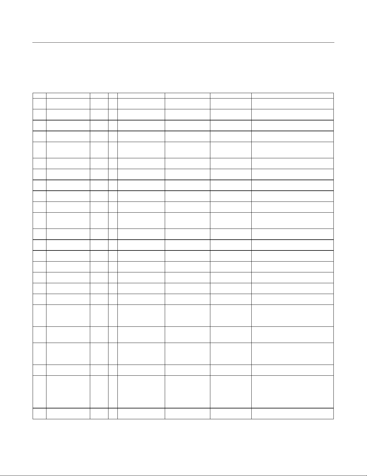
ITEM REF_DES DNI/DNP QTY MFG PART # MANUFACTURER VALUE DESCRIPTION
INDUCTOR; SMT (1206); FERRITE-BEAD;
2000; TOL=+/-25%; 0.3A
INDUCTOR; SMT (0806); WIREWOUND
CHIP; 2.2UH; TOL=+/-20%; 1.8A
WURTH
ELECTRONICS INC
INDUCTOR; SMT; SHIELDED; 2.2UH;
20%; 3.25A
KNOWLES
ACOUSTICS
IC; MICROPHONE; I2S; OUTPUT DIGITAL
MICROPHONE; SMT
TRAN; PCH; FIELD-EFFECT TRANSISTOR
SOT-23F; PD-(1W); I-(-3.9A); V-(-20V)
RES; SMT (0402); 1M; 1%; +/-100PPM/DEGC;
0.1000W
R2, R7, R11, R13, R16,
R19, R21, R23-R26
RES; SMT (0201); 10K; 1%; +/-100PPM/DEGC;
0.0500W
RES; SMT (0201); 2.2K; 1%; +/-100PPM/DEGC;
0.0500W
RES; SMT (0402); 2.7K; 1%; +/-100PPM/DEGC;
0.0630W
CRCW04021K40FK;
RC0402FR-071K4L
VISHAY DALE;
YAGEO PHICOMP
RES; SMT (0402); 1.4K; 1%;
+/-100PPM/DEGC; 0.0630W
CRCW04021K00FK;
MCR01MZPF1001
VISHAY DALE;
ROHM SEMI
KOA SPEER
ELECTRONICS INC
RES; SMT (0603); 0; JUMPER; JUMPER;
JUMPER
RES; SMT (0201); 100K; 1%;
+/-100PPM/DEGC; 0.0500W
RES; SMT (0402); 10K; 1%;
+/-100PPM/DEGC; 0.1000W
ERJ-2RKF3902X;
CRCW040239K0FK
PANASONIC;
VISHAY DALE
RES; SMT (0402); 39K; 1%;
+/-100PPM/DEGC; 0.0630W
RES; SMT (0402); 383K; 1%;
+/-100PPM/DEGC; 0.1000W
CRCW060356K2FK;
ERJ-3EKF5622
VISHAY;
PANASONIC
RES; SMT (0603); 56.2K; 1%;
+/-100PPM/DEGC; 0.1000W
THERMISTOR; SMT (0201);
10K OHM; TOL=+/-5%
SWITCH; SPST; SMT; 15V; 0.02A;
RINSULATION=100M OHM
IC; SNSR; COLOR CMOS VGA (640X480)
TECHNOLOGY; SMT ;
IC; UCON; ULTRA-LOW POWER;
FLASH=512KB; SRAM=160KB; WLP63
IC; PROT; 2-CHANNEL;
+/-30KV ESD PROTECTOR; UDFN6
EVKIT PART - IC; MAX78000; AI85;
90-0460; WLP81
IC; CODEC; ULTRA-LOW POWER STEREO AUDIO
CODEC; WLP30
Application Platform
MAX78000FTHR Bill of Materials (continued)
24 L4 - 1 HZ1206C202R-10 LAIRD TECHNOLOGIES 2000
25 L5, L7 - 2 DFE201612E-2R2M MURATA 2.2UH
Evaluates: MAX78000
26 L8, L9 - 2 74437324022
27 MK1 - 1 SPH0645LM4H-B
28 Q1 - 1 SSM3J327R,LF TOSHIBA SSM3J327R,LF
29 R1 - 1 ERJ-2RKF1004 PANASONIC 1M
30
31 R3, R12, R17, R18 - 4 ERJ-1GEF2201C PANASONIC 2.2K
32 R4, R8 - 2 CRCW04022K70FK VISHAY DALE 2.7K
33 R5, R9 - 2
34 R6, R10 - 2
35 R15 - 1 RK73Z1JT
36 R29 - 1 CRCW0201100KFK VISHAY DALE 100K
37 R30, R32, R34, R36 - 4 ERJ-2RKF1002 PANASONIC 10K
38 R35 - 1
39 R37 - 1 ERJ-2RKF3833 PANASONIC 383K
40 R38 - 1
41 RT1 - 1 NCP03XH103J05 MURATA 10K
- 11 CRCW020110K0FK VISHAY DALE 10K
RC0402FR-071KL;
YAGEO PHICOMP;
2.2UH
SPH0645LM4H-B
1.4K
1K
0
39K
56.2K
SILICON P-CHANNEL MOS TYPE (U-MOS VI);
RES; SMT (0402); 1K; 1%;
+/-100PPM/DEGC; 0.0630W
42 SW1-SW5 - 5 EVP-AA102K PANASONIC EVP-AA102K
43 U1 - 1 OVM7692-RYAA OMNIVISION OVM7692-RYAA
44 U2 - 1 MAX32625IWY+ MAXIM MAX32625IWY+
45 U3 - 1 MAX13202EALT+ MAXIM MAX13202EALT+
46 U4 - 1 MAX78000EXG+ MAXIM MAX78000EXG+
47 U5 - 1 MAX9867EWV+ MAXIM MAX9867EWV+
www.maximintegrated.com
EVPAA SERIES WITH GROUND TERMINAL;
LIGHT TOUCH SWITCH; RCONTACT=0.1 OHM;
CAMERACUBECHIP WITH OMNIPIXEL3-HS
HIGH-PERFORMANCE CORTEX-M4F
MICROCONTROLLER FOR WEARABLES;
ULTRA-LOW POWER ARM CORTEX-M4F
WITH CONVOLUTIONAL NEURAL NETWORK
ACCELERATOR; PACKAGE OUTLINE
DRAWING: 21-0735; LAND PATTERN:
Maxim Integrated
│
8
Page 9
MAX78000FTHR
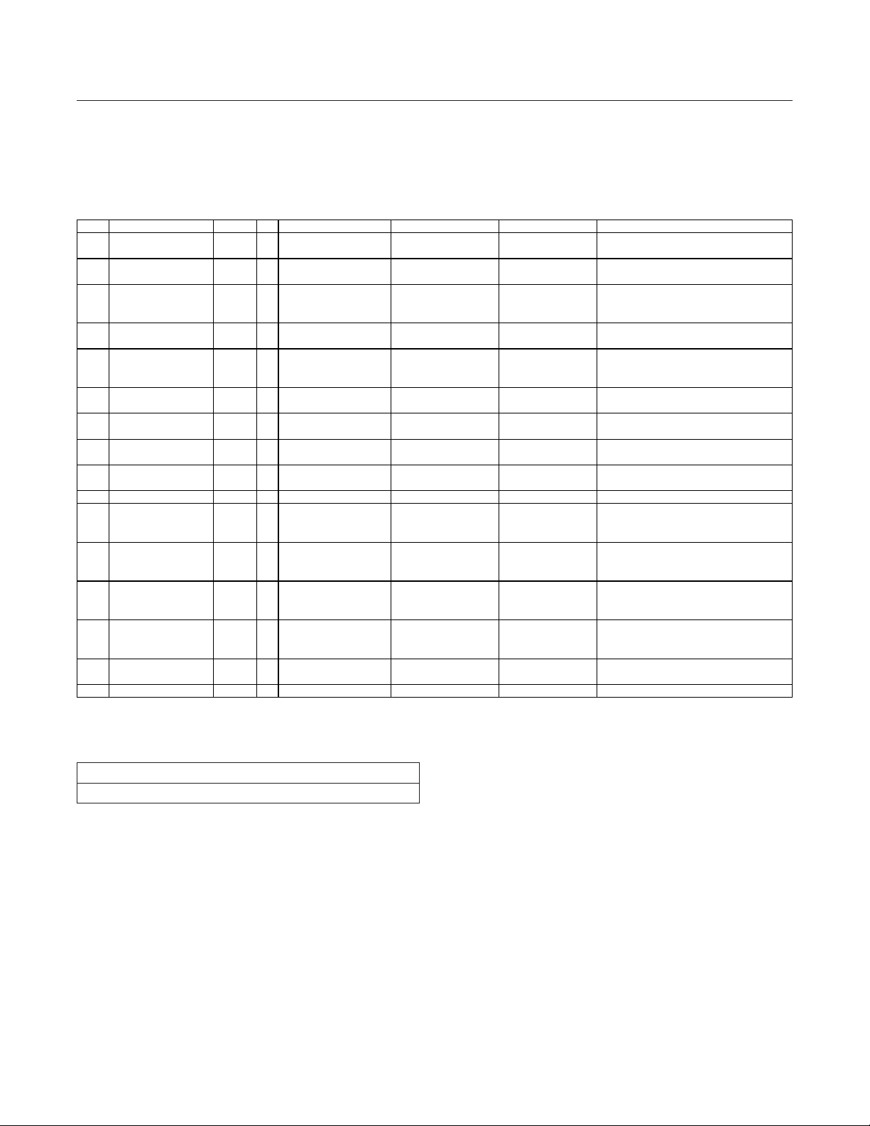
ITEM REF_DES DNI/DNP QTY MFG PART # MANUFACTURER VALUE DESCRIPTION
IC; TRANS; LOW-POWER DUAL-CHANNEL
LOGIC-LEVEL TRANSLATOR; TDFN8 2X2
IC; PWRM; WEARABLE POWER
MANAGEMENT SOLUTION; WLP56
IC; CONV; TINY 1.8V-5.5V INPUT;
NANOPOWER BUCK CONVERTER; DFN6
IC; MMRY; 1 MB ULTRA-LOW POWER
SERIAL SRAM; TSSOP8
IC; CONV; TINY 1.8V-5.5V INPUT;
NANOPOWER BUCK CONVERTER; DFN6
IC; CMOS; +/-15KV ESD-PROTECTED DUAL
CMOS SWITCH DEBOUNCERS; SOT23-6
IC; DRV; SINGLE BUFFER/DRIVER WITH
OPEN DRAIN OUTPUT; SC70-5
CRYSTAL; SMT 2.5MMX2MM; 15PF;
12.2880MHZ; +/-50PPM
CRYSTAL; SMT; 6PF; 32.768KHZ;
+/-20PPM; -0.036PPM/T2
57 PCB - 1 MAX78000_FTHR_APPS_A MAXIM PCB PCB:MAX78000_FTHR_APPS_A
CONNECTOR; MALE; THROUGH HOLE;
-65 DEGC TO +125 DEGC
CONNECTOR; MALE; THROUGH HOLE;
-65 DEGC TO +125 DEGC
CONNECTOR; MALE; SMT;
HEADER; STRAIGHT; 10PINS
CONNECTOR; MALE; BOARDMOUNT;
CONNECTOR; STRAIGHT; 10PINS
KOA SPEER
ELECTRONICS INC
RES; SMT (0603); 0; JUMPER;
JUMPER; JUMPER
TOTAL 150
Application Platform
MAX78000FTHR Bill of Materials (continued)
48 U6 - 1 MAX14595ETA+ MAXIM MAX14595ETA+
49 U7 - 1 MAX20303BEWN+ MAXIM MAX20303BEWN+
Evaluates: MAX78000
50 U8 - 1 MAX38642AELT+ MAXIM MAX38642AELT+
51 U9 - 1 N01S830HAT22I ON SEMICONDUCTOR N01S830HAT22I
52 U10 - 1 MAX38643AELT+ MAXIM MAX38643AELT+
53 U11 - 1 MAX6817EUT+ MAXIM MAX6817EUT+
54 U12 - 1 SN74LVC1G07DCK TEXAS INSTRUMENTS SN74LVC1G07DCK
55 Y1 - 1 SG-210STF 12.2880ML EPSON 12.2880MHZ
56 Y2, Y3 - 2 ABS07-32.768KHZ-6-T ABRACON 32.768KHZ
58 J4 DNI 1 PBC12SAAN
59 J8 DNI 1 PBC16SAAN
60 J2 DNP 0 FTSH-105-01-L-DV-K SAMTEC FTSH-105-01-L-DV-K
61 J3 DNP 0 TC2050-IDC-NL TAG-CONNECT TC2050-IDC-NL
62 R20 DNP 0 RK73Z1JT
SULLINS
ELECTRONICS CORP.
SULLINS
ELECTRONICS CORP.
PBC12SAAN
PBC16SAAN
0
300NANO-AMP IQ; 700MILLI-AMP
300NANO-AMP IQ; 700MILLI-AMP
BREAKAWAY; STRAIGHT; 12PINS;
BREAKAWAY; STRAIGHT; 16PINS;
0.05 (1.27MM) SMT MICRO
10-PIN NO-LEGS CABLE WITH RIBBON
Ordering Information
PART TYPE
MAX78000FTHR# Application Platform
#Denotes RoHS compliance.
www.maximintegrated.com
Maxim Integrated
│
9
Page 10
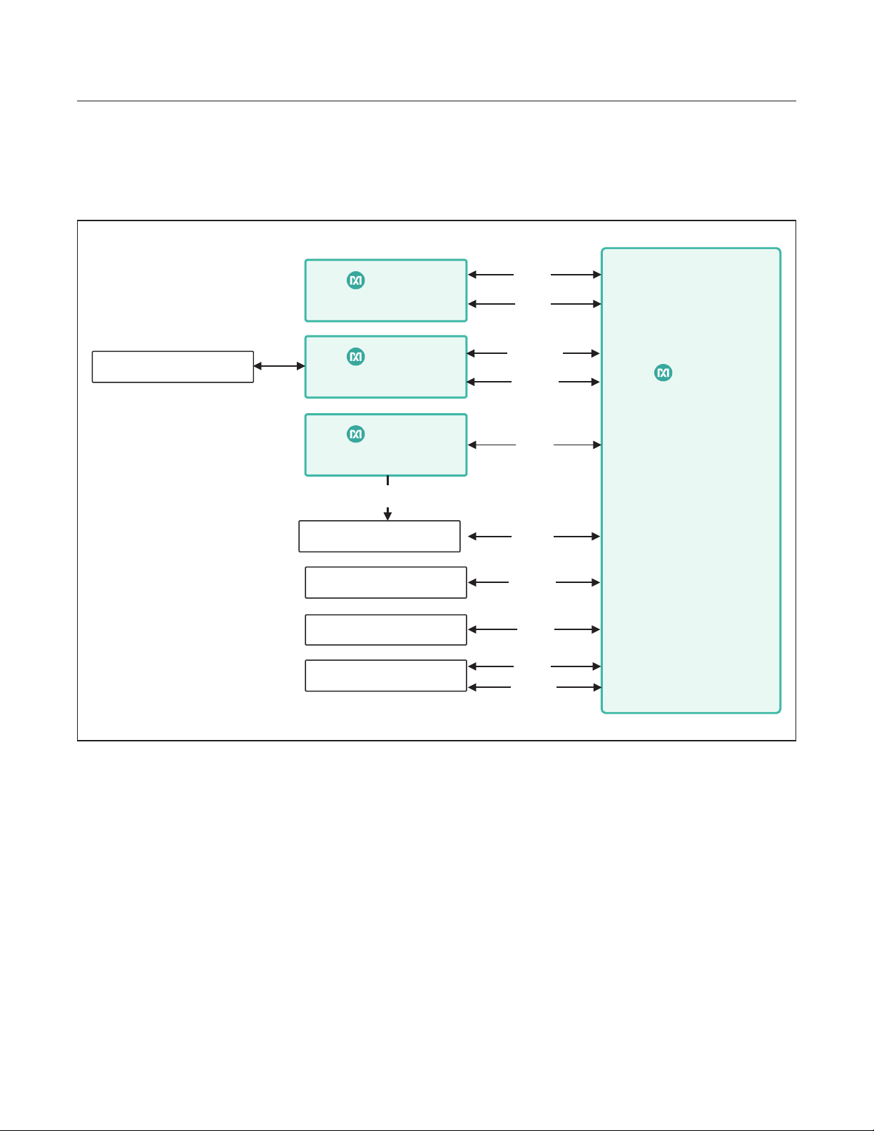
MAX78000FTHR
Application Platform
MAX78000FTHR Application Platform Diagram
Evaluates: MAX78000
MICRO USB-B CONNECTOR
MAX9867
STEREO AUDIO CODEC
MAX32625
ARM® CORTEX® M4F MCU
MAX20303
POWER MANAGEMENT IC
MPC0 VDD ENABLE
MICRO SD CARD
N01S830HAT22I
1MB SRAM
SPH0645LM4H-B
DIGITAL MICROPHONE
OVM7692-RYAA
IMAGE SENSOR
I2C
I2S
UART
SWD
I2C
SPI
QSPI
I2S
I2C
PCIF
MAX78000
ARM® CORTEX® M4F MCU
WITH CNN ACCELERATOR
www.maximintegrated.com
Maxim Integrated
│
10
Page 11
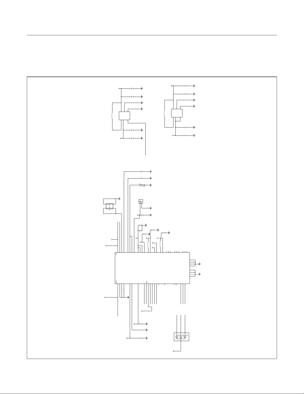
MAX78000FTHR
SW3
Application Platform
MAX78000FTHR Application Platform Schematics
Evaluates: MAX78000
21
L8
2.2UH
74437324022
U8
VCOREA
543
OUT
LX
MAX38642AELT+
2
SYS_OUT
C75C71
0.1UF 22UF
C73
R37
383K
GND
EN RSEL
IN
6
1
22UF
0.1UF
1V2 CNN POWER BOOST FOR MAX78000
C69
21
L9
2.2UH
74437324022
3V3_VREGI
U10
MAX38643AELT+
543
OUT
LX
2
SYS_OUT
22UF
0.1UF
C74 C76C70 C72
R38
56.2K
GND
IN
EN RSEL
6
1
22UF
3V3 VREGI FOR MAX78000
0.1UF
P2_5_BOOST_EN
4.7UF
C67C61
10K 22UF
RT1
2 1
POWER BUTTON
S2B-PH-K-S(LF)(SN)
4 3
EVP-AA102K
2 1
5
PMIC_PFN1
RST_N
PMIC_PFN2
PMIC RST_N
TEST POINT FOR
TP2
10K
1V8
F6
E2
D2
RST
PFN2
PFN1
U7
MAX20303BEWN+
ALRT
QSTRT
CTG
E6
D5
D6
R34 R32
10K
1V8
PMIC_ALRT_N
J9
2
1
BATTERY CONNECTOR
2.2UF
C68
VBATT
C66
2.2UF22UF
22UF
C25
C62
1V2
21
SYS_OUT
2V8
10K
R36
F5
E4
D4
F4H4A4F2
TPU
CAP
THM
VDIG
SET
CELL
CHGIN
F3
H5
C6
C60
0.1UF
L5
H7
H3
A5
B6
BAT
SYS
SYS
L2IN
BK1LX
L2OUT
SFOUT
INT
SDA
SCL
B2
B1
G2
PMIC_INT
I2C1_SCL
I2C1_SDA
1V8
R30
10K
C59
22UF
22UF
C64
1V8_MIC
2.2UH
1V8
G7
G6
L1IN
BK1OUT
MPC0
MPC1
MPC2
C4
C5
G4
SD_VDD_EN_N
PMIC_MPC2
PMIC_MPC1
BEFORE ENABLE
!! SET LDO2 TO 2.8V !!
1V8
21
L7
A7
G5
BK2LX
L1OUT
MPC4
MPC3
C3
G3
PMIC_MPC3
ON-BOARD MEMS MICROPHONE POWER
1.8V
LDO1 :
C65
2.2UH
B7
BK2OUT
3V3_VUSB
R35
39K
C58
VBUS
1UF
CHARGE CURRENT:51MA
DO NOT ENABLE BEFORE ADJUSTING
SET VOLTAGE TO 2.8V !!!
CONFIGURE AS LOAD SWITCH VIA I2C
22UF
B3B5B4
CPP
CPOUT
MON
E3
DO NOT SET ABOVE 2.8V !!!
CORE VOLTAGE FOR DAPLINK MCU
IO VOLTAGE FOR DAPLINK MCU
2.8V FOR THE IMAGE SENSOR
2.8V
1.2V
1.8V
LDO2 LV :
BUCK1 :
BUCK2 :
F7
E7
F1H2H1
CPN
BBLVLX
BBHVLX
BSTOUT
BSTLVLX
BSTHVLX
LED0
LED1
LED2
DRP
DRN
A2
A1
E1
C1
D1
PMIC_LED2
PMIC_LED0
PMIC_LED1
PMIC_LED1
PMIC_LED2
PMIC_LED0
2431
B
R
G
D2
+
SML-LX0404SIUPGUSB
C7
BBOUT
BBGND
D7
BSTGND
G1
BK2GND
A6
BK1GND
H6
HDGND
A3
DGND
C2
GSUB
D3
AGND
E5
PMIC RGB LED
www.maximintegrated.com
SYS_OUT
Maxim Integrated
│
11
Page 12
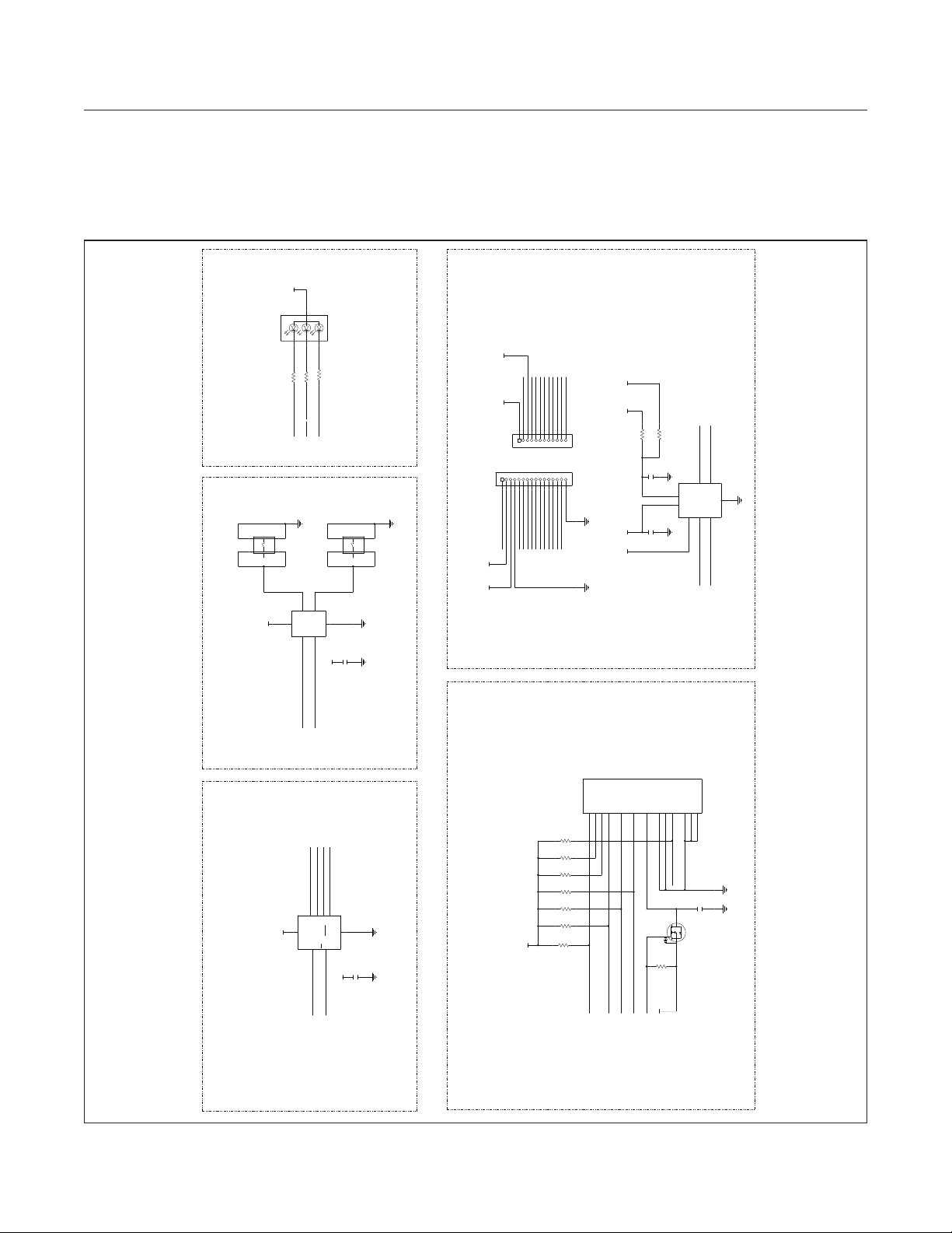
MAX78000FTHR
QSPI SRAM USER BUTTONS RGB LED
Application Platform
MAX78000FTHR Application Platform Schematics (continued)
3V3_VREGI
+
D1
GBR
SML-LX0404SIUPGUSB
243 1
1K
1.4K
2.7K
R9
R10
R8
5
3V3_VREGI
4 3
2 1
U11
P2_0_LED_R
SW1
EVP-AA102K
5
VCC
MAX6817EUT+
P2_2_LED_B
1
IN1
OUT1
6
P2_1_LED_G
3
OUT2 IN2
4
GND
2
3V3_VREGI
SYS_OUT VBUS
J8
PBC16SAAN
4 3
SW2
2 1
EVP-AA102K
5
DUT_3V3_RSTN
3V3_VREGI1V8
0.1UF
C79
EXTERNAL FTHR HEADER CONNECTORSMICRO SD CARD CONNECTOR
J4
PBC12SAAN
1
P2_3_AIN
PMIC_PFN1
P2_4_AIN
P1_6_GPIO
P1_0_RV_TCK
P1_1_RV_TMS
PMIC_MPC3
987654321
PMIC_MPC1
QSPI0_SDIO3
QSPI0_SDIO2
PMIC_MPC2
SD_SPI_SCLK
QSPI0_SS1
SD_SPI_DI
P0_19_GPIO
SD_SPI_DO
P3_1_GPIO
I2C_SCL_FTHR
I2C_SDA_FTHR
12111098765432
16151413121110
P2_6_UART_RX
P2_7_UART_TX
PACKOUT
PACKOUT
3V3_VREGI
1V8 1V8
1V8
R15
Evaluates: MAX78000
DNI
0
0
R20
DO NOT POPULATE R15 AND R20 BOTH
I2C_SDA_FTHR
I2C_SCL_FTHR
I2C LEVEL SHIFTER
7
6
U6
MAX14595ETA+
IOVCC2
IOVCC1
8
VCC
5
GND
1
VL
/TS
IOVL2
IOVL1
2
3
4
C51 C52
0.1UF 1UF
I2C1_SCL
I2C1_SDA
3V3_VREGI
P0_2_BUTTON1
U9
N01S830HAT22I
VCC
P1_7_BUTTON_2
QSPI0_SDIO2
SD_SPI_DO
SD_SPI_DI
2
563
SI/SIO0
NC/SIO2
SO/SIO1
SCK
CS
1
SD_SPI_SCLK
SRAM_CS
QSPI0_SDIO3
7
HOLD/SIO3
VSS
3V3_VREGI
J6
475710001
DAT1
DAT0
CMD
CD/DAT3
DAT2
P1P8P7
P3P5P2
R26
10K 10K10K 10K 10K 10K 10K
DET
POL
GND
GND
GND
VSS
CLK
VDD
P6
P4
G4G3G2G1G5
SD_DET
0.1UF
C57
3
SD_VDD_EN_N
SD_SPI_SCLK
1
R11
10K
3V3_VREGI
D
G
Q1
S
SSM3J327R,LF
2
4 8
R16 R19 R23R21 R24 R25
3V3_VREGI
0.1UF
C87
SD_SPI_DI
SD_SPI_CS
SD_SPI_DO
www.maximintegrated.com
Maxim Integrated
│
12
Page 13
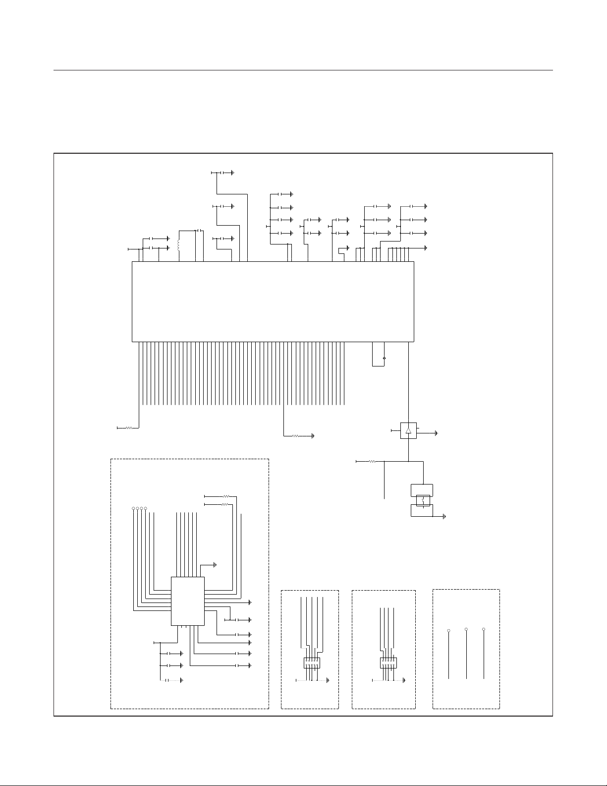
MAX78000FTHR
Application Platform
MAX78000FTHR Application Platform Schematics (continued)
C20C19C15
22UF
VCOREA
Evaluates: MAX78000
MAX78000
VREGO_A
3V3_VREGI
U4
MAX78000EXG+
R2
C6
VREGI
P0.0/UART0_RX
J9J8J7
P0_0_UART0_RX
10K
VREGI : 3.3V
47UF
C11
C41
1UF
C9
A9
VREGI
VSSPWR
P0.2/TMR0_0/UART0_CTS
P0.4/QSPI0_SS0/TMR0_0B/TMR0_CAPEVENT0
P0.1/UART0_TX
P0.3/CLKEXT/TMR0_1/UART0_RTS
P0.5/QSPI0_MOSI/TMR0_1B/TMR0_CAPEVENT1
P0.6/QSPI0_MISO/OWM_IO
H9H8H7
G7
SD_SPI_DO
P0_1_UART0_TX
P0_2_BUTTON1
SD_SPI_DI
P0_3_CAM_PDOWN
SD_SPI_CS
MLP2012H2R2MT0S1
21
L1
2.2UH
B9
LXA
P0.7/QSPI0_SCK/OWM_PE
P0.8/QSPI0_SDIO2/TMR0_0
P0.9/QSPI0_SDIO3/TMR0_1
P0.10/I2C0_SCL/QSPI0_SS2
F6
E6
H6
G6
QSPI0_SDIO3
QSPI0_SDIO2
SRAM_CS
SD_SPI_SCLK
VREGO_B
C16
3300PF
VREGO_A
C8
A8
LXB
VBST
P0.12/UART1_RX/TMR1_0B/TMR1_CAPEVENT0
P0.17/I2C1_SDA/PT3
P0.13/UART1_TX/TMR1_1B/TMR1_CAPEVENT1
P0.18/PT0/OWM_IO
P0.14/TMR1_0/I2S_CLKEXT
P0.15/TMR1_1/PCIF_VSYNC
P0.11/I2C0_SDA/QSPI0_SS1
P0.16/I2C1_SCL/PT2
F5
E5
H5
H4
D6
D5
G5
G4
I2C1_SDA
I2C1_SCL
PCIF_VSYNC
QSPI0_SS1
PCIF_XVCLK
AUD_CODEC_CLK
P0_13_INTCDC
SD_DET
22UF
22UF
P0.19/PT1/OWM_PE
P0.20/QSPI1_SS0/PCIF_IO0
P0.21/QSPI1_MOSI/PCIF_IO1
F4
E4
D4
PCIF_IO1
PCIF_IO0
P0_19_GPIO
B8
A7
VREGO_A
VREGO_B
P0.22/QSPI1_MISO/PCIF_IO2
P0.23/QSPI1_SCK/PCIF_IO3
P0.24/QSPI1_SDIO2/PCIF_IO4
P0.25/QSPI1_SDIO3/PCIF_IO5
P0.26/TMR2_0/PCIF_IO6
J3
F3
E3
H3
G3
PCIF_IO3
PCIF_IO2
PCIF_IO4
PCIF_IO5
PCIF_IO6
VREGO_C >> VCOREA
B7
VREGO_C
P0.27/TMR2_1/PCIF_IO7
P0.29/SWCLK
P0.28/SWDIO
P0.30/I2C2_SCL/PCIF_IO8
P0.31/I2C2_SDA/PCIF_IO9
J2
J1
H2
H1
G2
SWDCLK
I2C2_SDA
I2C2_SCL
PCIF_IO7
SWDIO
VCOREA
P1.0/UART2_RX/RV_TCK
P1.2/I2S_SCK/RV_TDI
P1.1/UART2_TX/RV_TMS
F2
F1
G1
P1_0_RV_TCK
P1_1_RV_TMS
I2S_SCK/RV_TDI
C55C53C9 C17
0.1UF 1UF
1UF
0.1UF
E1D9D8D7
VCOREA
P1.3/I2S_WS/RV_TDO
P1.5/I2S_SDO/TMR3_1
P1.4/I2S_SDI/TMR3_0
E2
B1
D3
D2
I2S_WS/RV_TDO
I2S_SDO
P1_6_GPIO
I2S_SDI
VREGO_B
VCOREA
P1.7/TMR3_1/PCIF_IO11
P1.9/PCIF_XCLK/TXEV0
P1.6/TMR3_0/PCIF_IO10
P1.8/PCIF_HSYNC/RXEV0
B2
A2
C2
PCIF_HSYNC
PCIF_XCLK
P1_7_BUTTON_2
100K
R29
VCOREB = VREGO_B
1UF
C18C12
0.1UF
VCOREBP2.0/AIN0 / AIN0N
P2.4/AIN4 / AIN2N/LPTMR0
P2.2/AIN2 / AIN1N
P2.3/AIN3 / AIN1P
P2.1/AIN1 / AIN0P
F9F8F7
E8
E7
P2_2_LED_B
P2_0_LED_R
P2_1_LED_G
P2_4_AIN
P2_3_AIN
VDDA = VREGO_A = 1V8
C42
1UF
VREGO_A
0.1UF
C13
C7
B6
VSSA
VDDA
P2.7/LPTMR1_CLK/AIN7 / AIN3P/LPUART_TX
P2.6/LPTMR0_CLK/AIN6 / AIN3N/LPUART_RX
P2.5/AIN5 / AIN2P/LPTMR1
P3.0/PWRDN/WAKEUP
P3.1/RTC_SQWO/WAKEUP
B3
C3
G9
G8
P3_1_GPIO
P2_7_UART_TX
PMIC_PFN2
P2_6_UART_RX
P2_5_BOOST_EN
3V3_VREGI
J4
VDDIOH
VREGO_A
C1
A3
VDDIOH
VDDIOH
AT VREGI LEVEL
VDDIOH MUST BE
C45
1UF
C56C54
0.1UF
0.1UF
J5
D1
A4
VDDIO
VDDIO
VDDIO
32KIN
32KOUT
B5
A5
21
Y3
R7
10K
VDDIO = VREGO_A = 1V8
VREGO_A
C5
C4
A6
A1
VSS
VSS
VSS
VSS
32.768KHZ
U12
SN74LVC1G07DCK
5
VREGO_A
C46
1UF0.1UF
C10
0.1UF
C14
J6
E9
VSS
VSS
RSTN
B4
APPROX 25KOHM
RSTN IS INTERNALLY PULLED UP TO VDDIOH
DUT_3V3_RSTN
4
1
VCC
3
GND NC
A Y
2
TP6
TP5
PCIF_HSYNC
PCIF_XVCLK
IMAGE SENSOR
www.maximintegrated.com
TP8
TP7
PCIF_VSYNC
PCIF_XCLK
PCIF_IO1
PCIF_IO0
2V8
U1
OVM7692-RYAA
C2 C40
C26
R12R3
1V8
1V8
2.2K 2.2K
PCIF_IO4
PCIF_IO6
PCIF_IO3
PCIF_IO7
PCIF_IO2
PCIF_IO5
C4
B5A5C5D5D2
E2
D2
D3
EGND
D4/MCP
D6/MDP
D5/MCN
D7/MDN
D1
C3
D0
E3
VSYNC
D1
PCLK
D3
HREF
E1
XVCLK
E5
AGND
VREF2
VREF1NCNC
AVDD
B3
A4
B4
A1
A2
A3
0.1UF
1UF
22UF
I2C2_SDA
P0_3_CAM_PDOWN
I2C2_SCL
1V8
0.1UF
C6 C7
0.1UF
0.1UF
C1 C3
0.1UF
I2C ADDRESS : 0X78 - 0X79
SWDIO
J2
FTSH-105-01-L-DV-K
P0_1_UART0_TX
SWDCLK
EXTERNAL_RST
P0_0_UART0_RX
10987654321
DNI
SIOD
B2
SIOC
C1
PWDN
B1
DOGND
C2
DOVDD
D4
DVDD
E4
1V8
ARM SWD
RISC-V JTAG
1V8
P1_1_RV_TMS
J1
FTSH-105-01-L-DV-K
EXTERNAL_RST
DAPLINK RESET
P1_0_RV_TCK
I2S_SCK/RV_TDI
I2S_WS/RV_TDO
10987654321
SIGNAL
5
4 3
SW4
2 1
EVP-AA102K
TEST POINTS
TP3
TP1
I2S_SDO
P0_0_UART0_RX
TEST POINT FOR I2S_SDO
TEST POINT FOR UART0_RX
Maxim Integrated
TP4
P0_1_UART0_TX
TEST POINT FOR UART0_TX
│
13
Page 14
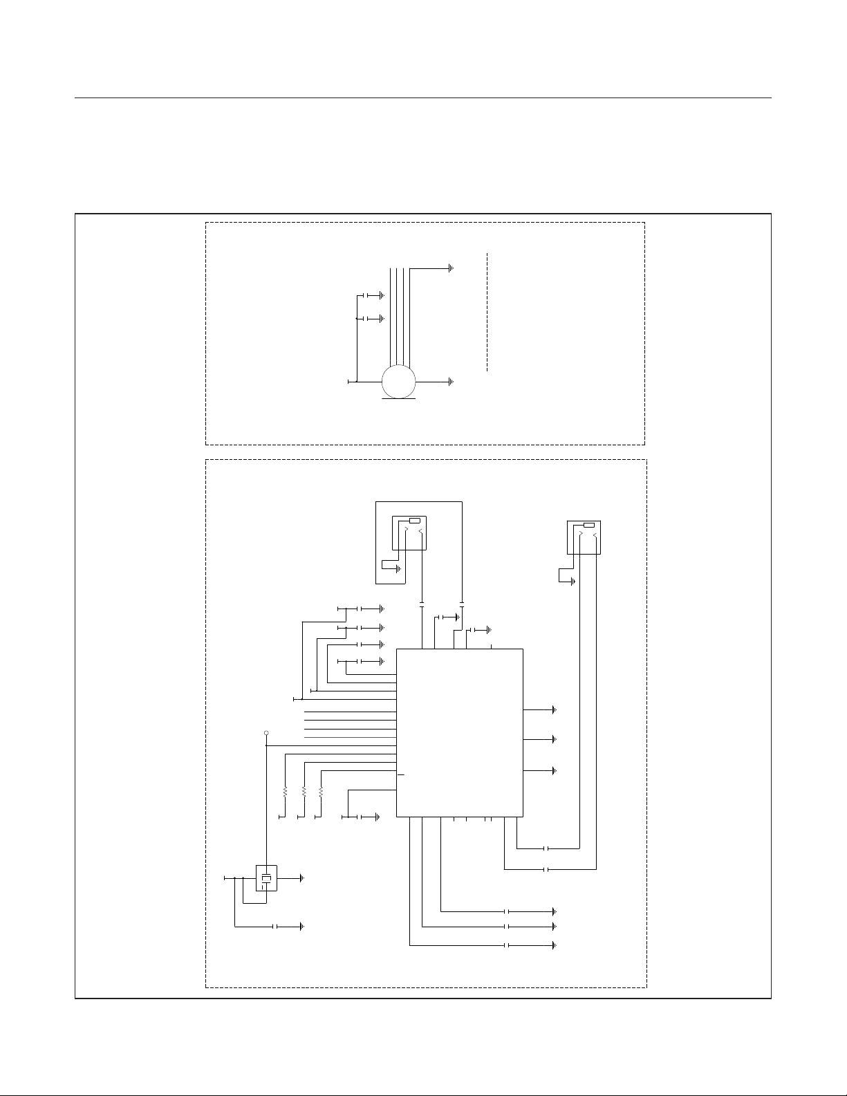
MAX78000FTHR
Application Platform
MAX78000FTHR Application Platform Schematics (continued)
C29C28
220PF0.1UF
DATA TRI-STATE
OPERATION
DRIVES DATA0
WS
1
AUDIO - DIGITAL MICROPHONE
CONFIGURE LDO1 OF PMIC AS
LOAD SWITCH AND TURN ON
1V8_MIC TO USE MICROPHONE
MK1
SPH0645LM4H-B
5
1V8_MIC
I2S_WS/RV_TDO
I2S_SCK/RV_TDI
I2S_SDI
1
4
WS
BCLK
DATA
VDD
236
SEL
GND
Evaluates: MAX78000
AND AUDIO MAX78000
SHARED BY THE CODEC
12.288MHZ CLOCK IS
1V8
Y1
4
12.2880MHZ
TP9
R17
1V8
AUD_CODEC_CLK
3
OUT
VCC
GND
ST
1
0.1UF
C24
J7
SJ-3523-SMT
RING
TIP
SLEEVE
213
3.5MM AUDIO JACK
SINGLE ENDED
STEREO LINE OUT
1UF
1UF1UF1UF
1UF
C30 C31 C33 C36
1V8 1V8 1V8
1V8
1V8
2.2K
2.2K
10K
R18
R13
1V8
1V8
2
C27
1V8
U5
PVDD
E2
PREG
A5
AVDD
A4
DVDD
A1
D1
I2S_SDI
SDIN
I2S_SDO
C2
LRCLK
C1
I2S_WS/RV_TDO
BCLK
B1
I2S_SCK/RV_TDI
MCLK
B2
SCL
I2C1_SCL
B3
SDA
I2C1_SDA
A3
IRQ
C3
P0_13_INTCDC
E1
C34
MAX9867EWV+
SDOUT
DVDDIO
REF
B4
220UF
E3
LOUTP
REG
B5
220UF1UF
C37
C35
1UF
C32
D3
E4
D2
LOUTN
MICBIAS
B6
ROUTP
ROUTN
MICLP/DIGMICDATA
MICLN/DIGMICCLK
C6
C5
MICRP
C4
D4
JACKSNS/AUX
MICRN
D6
LINR
LINL
E6
D5
2.2UF 1UF 1UF
C21 C22 C23
J5
LRCLK AND BCLK ARE INPUTS
I2S IS BY DEFAULT :SLAVE
I2C ADDRESS: 0X30 - 0X31
PGND
E5
AGND
A6
DGND
A2
AUDIO JACK
GND REF NEAR
1UF
C49C48
1UF
SJ-3523-SMT
RING
SLEEVE
LINE_IN_RIGHT
TIP
STEREO LINE IN
213
LINE_IN_LEFT
3.5MM AUDIO JACK
www.maximintegrated.com
AUDIO - LOW-POWER STEREO AUDIO CODEC - STEREO LINE IN AND LINE OUT
Maxim Integrated
│
14
Page 15
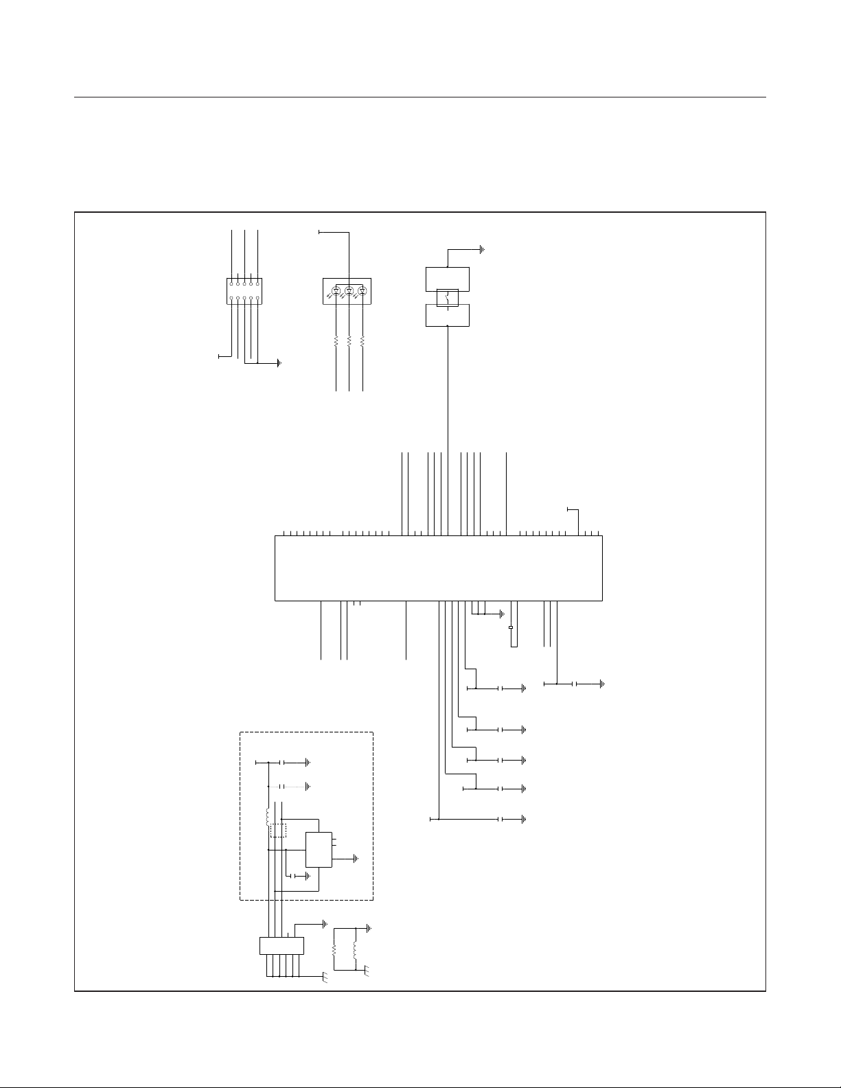
MAX78000FTHR
Application Platform
MAX78000FTHR Application Platform Schematics (continued)
3V3_VUSB
DBG_TX
DBG_SRST
10
J3
TC2050-IDC-NL
12345 6
FOR MAX3262 SWD
TAG-CONNECT CABLE PADS
DBG_SWD
1V8
DBG_RX
789
DBG_SWC
DNI
D3
R
SML-LX0404SIUPGUSB
2
DAPLINK STATUS LED
2.7K
R4
R_LED
+
1.4K
R5
13
B
B_LED
G
4
1K
R6
G_LED
34
SW5
EVP-AA102K
12
5
DAPLINK FIRMWARE UPDATE BUTTON
Evaluates: MAX78000
R_LED
P2.4
G_LED
P2.5
P0_0_UART0_RX
SWDCLK
P3.5
P3.2
P2.7
P2.6
VDD12
VRTC
VDD18
E1
A8
D8C1C9
P3.6
P3.1
P3.0
P3.4
P3.3
VDDIO
VSS
VSS
VDDIOH
VSS
B8
C8
D1
DBG_RX
DBG_TX
A2B2A1C4C3B1D4C2D3E4D2E3F2F1F3G1G2G3F4G4E5F5G5E6F6G6D5D6G7F7G8G9E7F8F9D7C5C6C7
P0.6
P0.3
P0.4
P0.1
P0.5
P0.0
P0.2
U2
MAX32625IWY+
SRSTN
A3
DBG_SRST
P0.7
P1.1
P1.0
TMS/SWDIO/IO
TCK/SWCLK
B4B7B6
B5
DBG_SWC
DBG_SWD
E2
P1.3
P1.4
P1.2
TDI
TDO
P2.2
P2.1
P2.0
P2.3
P1.7
P1.5
P1.6
RSTN
B3
RST_N
SWDIO
P0_1_UART0_TX
B_LED
1V8 3V3_VUSB
1.0UF0.1UF
VBUS
C5 C8
DP
DM
L4
2000
1 2
U3
MAX13202EALT+
I/O2I/O1
5
NC
2
NC
1
VCC
6
GND
1.0UF
C4
3 4
1V2
1V8
1V8
C39 C43 C44 C47 C50
EXTERNAL_RST
P4.0
P3.7
32KOUT
32KIN
A9
B9
Y2
1 2
32.768KHZ
1UF 1UF 1UF
1UF
1UF
VREGO_A
A4A5A6
P4.3
P4.2
P4.1
P4.4
P4.5
DM
DP
E9
E8
DP
DM
A7
P4.7
P4.6
AIN3
AIN2
AIN1
AIN0
VDDB
D9
1UF
C38
3V3_VUSB
www.maximintegrated.com
1
D-
VBUS
CN1
47346-0001
678
MICRO USB CONNECTOR
325
D+
4
ID
GND
SHIELD
9
10
11
L3
R1
1M
220
1 2
Maxim Integrated
│
15
Page 16

MAX78000FTHR
Evaluates: MAX78000
Application Platform
Revision History
REVISION
NUMBER
0 11/20 Release for market intro —
REVISION
DATE
DESCRIPTION
PAGES
CHANGED
For pricing, delivery, and ordering information, please visit Maxim Integrated’s online storefront at https://www.maximintegrated.com/en/storefront/storefront.html.
Maxim Integrated cannot assume responsibility for use of any circuitry other than circuitry entirely embodied in a Maxim Integrated product. No circuit patent licenses
are implied. Maxim Integrated reserves the right to change the circuitry and specications without notice at any time.
Maxim Integrated and the Maxim Integrated logo are trademarks of Maxim Integrated Products, Inc.
©
2020 Maxim Integrated Products, Inc.
│
16
 Loading...