

Page 1
General Description
The MAX700/MAX701/MAX702 are supervisory circuits
used to monitor the power supplies in microprocessor
(µP) and digital systems. The RESET/RESET outputs of
the MAX700/MAX701/MAX702 are guaranteed to be in
the correct state for V
CC
voltages down to +1V (Figure 4).
They provide excellent circuit reliability and low cost by
eliminating external components and adjustments when
used with +5V-powered circuits.
The MAX702 is the simplest part in the family. When
V
CC
falls to 4.65V, RESET goes low. The MAX702 also
provides a debounced manual reset input. The
MAX701 performs the same functions but has both
RESET and RESET outputs. Their primary function is to
provide a system reset. Accordingly, an active reset
signal is supplied for low supply voltages and for at
least 200ms after the supply voltage reaches its operating value.
In addition to the features of the MAX701 and MAX702,
the MAX700 provides preset or adjustable voltage
detection so thresholds other than 4.65V can be selected, and adjustable hysteresis. All parts are supplied in
8-pin PDIP and Narrow SO packages in commercial
and extended temperature ranges.
Applications
Computers
Controllers
Intelligent Instruments
Automotive Systems
Critical µP Power Monitoring
Features
♦ Min 200ms RESET Pulse on Power-Up, Power-
Down, and During Low-Voltage Conditions
♦ Reset Threshold Factory Trimmed for +5V
Systems
♦ No External Components or Adjustments with
+5V-Powered Circuits
♦ Debounced Manual Reset Input
♦ Preset or Adjustable Voltage Detection (MAX700)
♦ Adjustable Hysteresis (MAX700)
♦ 8-Pin PDIP and Narrow SO Packages
MAX700/MAX701/MAX702
Power-Supply Monitor with Reset
________________________________________________________________
Maxim Integrated Products
1
19-2690; Rev 2; 12/07
For pricing delivery, and ordering information please contact Maxim Direct at 1-888-629-4642,
or visit Maxim’s website at www.maxim-ic.com.
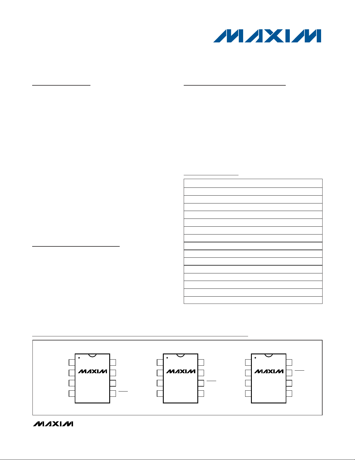
RESET
RESETGND
1
2
87V
CC
CTLSENSE
HYST
MR
DIP/SO
TOP VIEW
3
4
6
5
MAX700
RESET
RESET
GND
1
2
87V
CC
N.C.N.C.
N.C.
MR
DIP/SO
3
4
6
5
MAX701
N.C.
N.C.
RESET
GND
1
2
87N.C.
V
CC
N.C.
MR
DIP/SO
3
4
6
5
MAX702
Pin Configurations
Ordering Information
*
Devices in PDIP and SO packages are available in both leaded and lead-free packaging. Specify lead free by adding the +
symbol at the end of the part number when ordering.
PART* TEMP RANGE PIN-PACKAGE
MAX700C/D 0°C to +70°C Dice
MAX700CPA 0°C to +70°C 8 PDIP
MAX700CSA 0°C to +70°C 8 Narrow SO
MAX700EPA -40°C to +85°C 8 PDIP
MAX700ESA -40°C to +85°C 8 Narrow SO
MAX701C/D 0°C to +70°C Dice
MAX701CPA 0°C to +70°C 8 PDIP
MAX701CSA 0°C to +70°C 8 Narrow SO
MAX701EPA -40°C to +85°C 8 PDIP
MAX701ESA -40°C to +85°C 8 Narrow SO
MAX702C/D 0°C to +70°C Dice
MAX702CPA 0°C to +70°C 8 PDIP
MAX702CSA 0°C to +70°C 8 Narrow SO
MAX702EPA -40°C to +85°C 8 PDIP
MAX702ESA -40°C to +85°C 8 Narrow SO
Page 2
MAX700/MAX701/MAX702
Power-Supply Monitor with Reset
2 _______________________________________________________________________________________
ABSOLUTE MAXIMUM RATINGS
Stresses beyond those listed under “Absolute Maximum Ratings” may cause permanent damage to the device. These are stress ratings only, and functional
operation of the device at these or any other conditions beyond those indicated in the operational sections of the specifications is not implied. Exposure to
absolute maximum rating conditions for extended periods may affect device reliability.
VCC......................................................................-0.3V to +15.5V
Voltage (with respect to GND) at RESET, RESET,
HYST, CTL, SENSE ............................................-0.3V to V
CC
Operating Temperature Range
C Suffix .............................................................0°C to +70°C
E Suffix...........................................................-40°C to +85°C
Rate of Rise, V
CC
............................................................100V/µs
Power Dissipation, Any Package .....................................380mW
Storage Temperature Range .............................-55°C to +150°C
Lead Temperature (soldering, 10s)..................................+300°C
ELECTRICAL CHARACTERISTICS
(VCC= +5V, CTL = GND on MAX700, TA= +25°C, unless otherwise noted.)
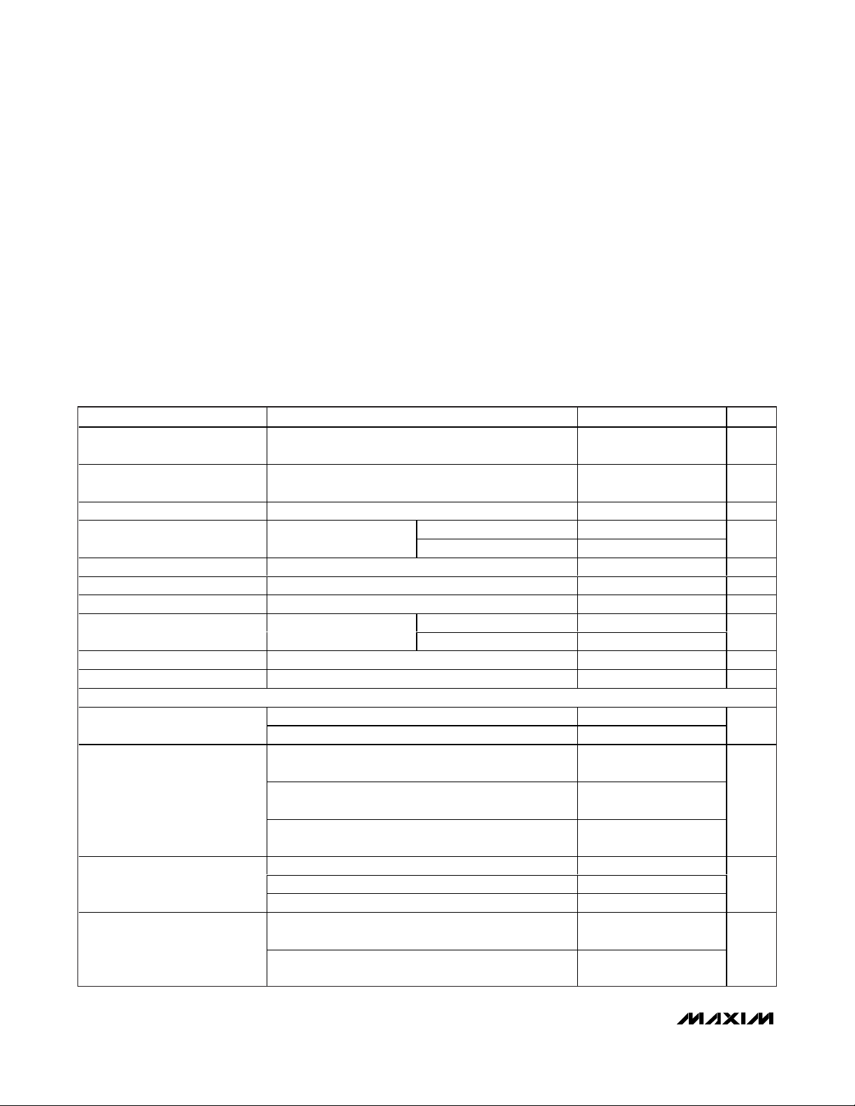
PARAMETER CONDITIONS MIN TYP MAX UNITS
VCC Monitor Voltage Range
(MAX700 Only)
Min VCC for Valid Reset Output,
Declining Supply
Supply Current 100 200 µA
Reset Threshold TA = T
Internal Hysteresis HYST not connected 30 mV
Reset Output Pulse Width 200 350 500 ms
RESET Fall Time MAX700/MAX701 only, C
VCC Pulse Duration Guaranteeing 5V to 4V VCC pulse
MR Input Threshold 0.7 V
MR Pullup Current -5 -30 µA
MAX700
RESET Output Low
RESET Output High
RESET Output High
T
= T
= T
MIN
MIN
MIN
to T
to T
to T
A
T
A
, CTL = V
MAX
, RESET ≤ 0.4V when sinking 1mA 1.5 1 V
MAX
MAX
CC
Power-up 4.50 4.65 4.75
Power-down 4.50 4.62 4.75
= 100pF 200 ns
LOAD
No reset 10 1
Reset 100 10
I
= 3.2mA, VCC = 5V 0.4
SINK
= 1.6mA, VCC = 3V 0.4
I
SINK
I
I
I
I
I
I
I
I
= 3.2mA, VCC = 4.25V
SOURCE
= 1.6mA, VCC = 3V
SOURCE
= 0.5mA, VCC = 1.5V
SOURCE
= 16mA, VCC = 4.25V 0.4
SINK
= 1.6mA, VCC = 3V 0.4RESET Output Low
SINK
= 0.4mA, VCC = 1.5V 0.4
SINK
= 3.2mA, VCC = 5V
SOURCE
= 1.6mA, VCC = 3V
SOURCE
315V
V
-
CC
0.4
V
-
CC
0.4
V
-
CC
0.4
V
-
CC
0.4
V
-
CC
0.4
V
µs
V
V
V
V
Page 3
MAX700/MAX701/MAX702
Power-Supply Monitor with Reset
_______________________________________________________________________________________ 3
ELECTRICAL CHARACTERISTICS (continued)
(VCC= +5V, CTL = GND on MAX700, TA= +25°C, unless otherwise noted.)
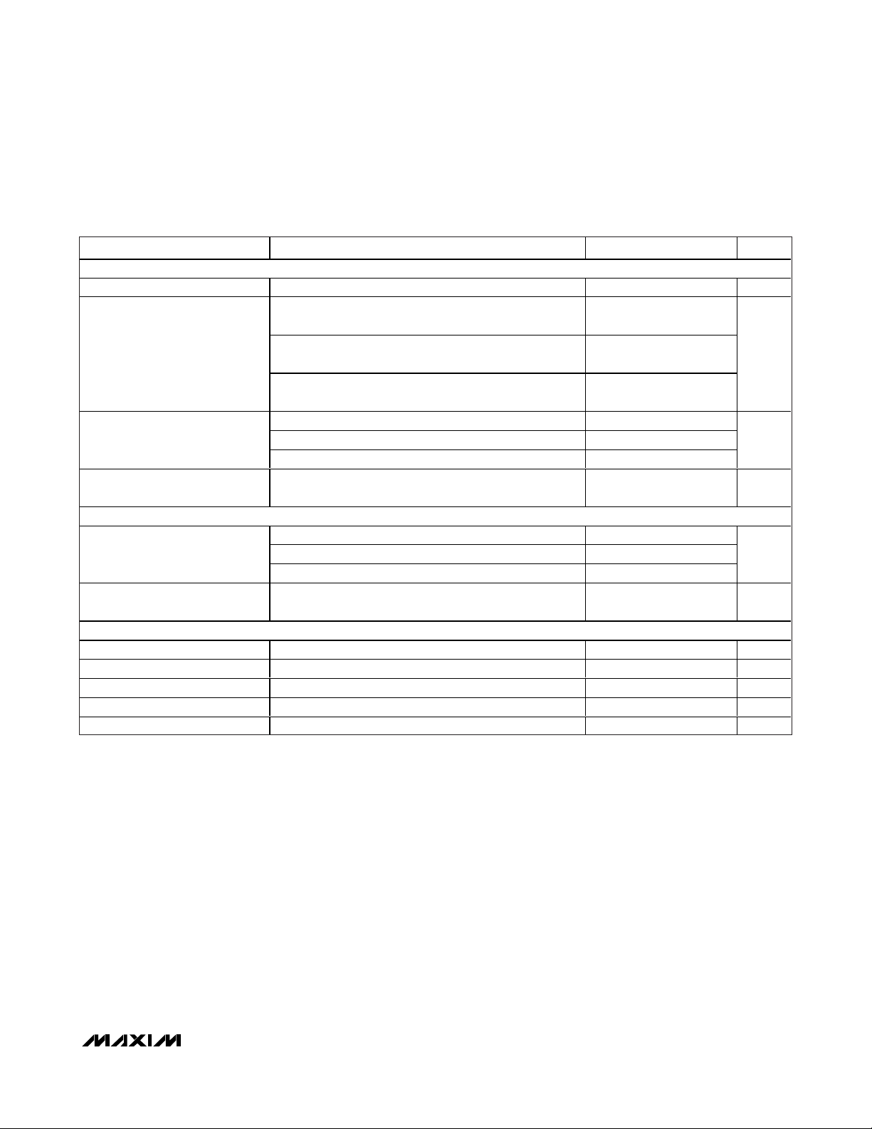
PARAMETER CONDITIONS MIN TYP MAX UNITS
MAX701
RESET Output Low I
RESET Output High
RESET Output High I
MAX702
RESET Output Low
RESET Output High I
MAX700 ONLY (CTL = VCC, unless otherwise noted)
SENSE Input Threshold TA = T
SENSE Input Current 0.1 nA
HYST Input On-Resistance 0.5 kΩ
CTL Input Threshold 2V
CTL Pulldown Current 30 100 µA
= 16mA, VCC = 5V 0.4 V
SINK
V
-
I
SOURCE
I
SOURCE
I
SOURCE
I
SINK
I
SINK
I
SINK
SOURCE
I
SINK
I
SINK
I
SINK
SOURCE
= 3.2mA, VCC = 4.25V
= 1.6mA, VCC = 3V
= 0.5mA, VCC = 1.5V
= 3.2mA, VCC = 4.25V 0.4
= 1.6mA, VCC = 3V 0.4RESET Output Low
= 0.4mA, VCC = 1.5V 0.4
= 3.2mA, VCC = 5V
= 3.2mA, VCC = 4.25V 0.4
= 1.6mA, VCC = 3V 0.4
= 0.4mA, VCC = 1.5V 0.4
= 3.2mA, VCC = 5V
to T
MIN
MAX
CC
0.4
V
-
CC
0.4
V
-
CC
0.4
V
-
CC
0.4
V
-
CC
0.4
1.25 1.29 1.35 V
V
V
V
V
V
Page 4
MAX700/MAX701/MAX702
Power-Supply Monitor with Reset
4 _______________________________________________________________________________________
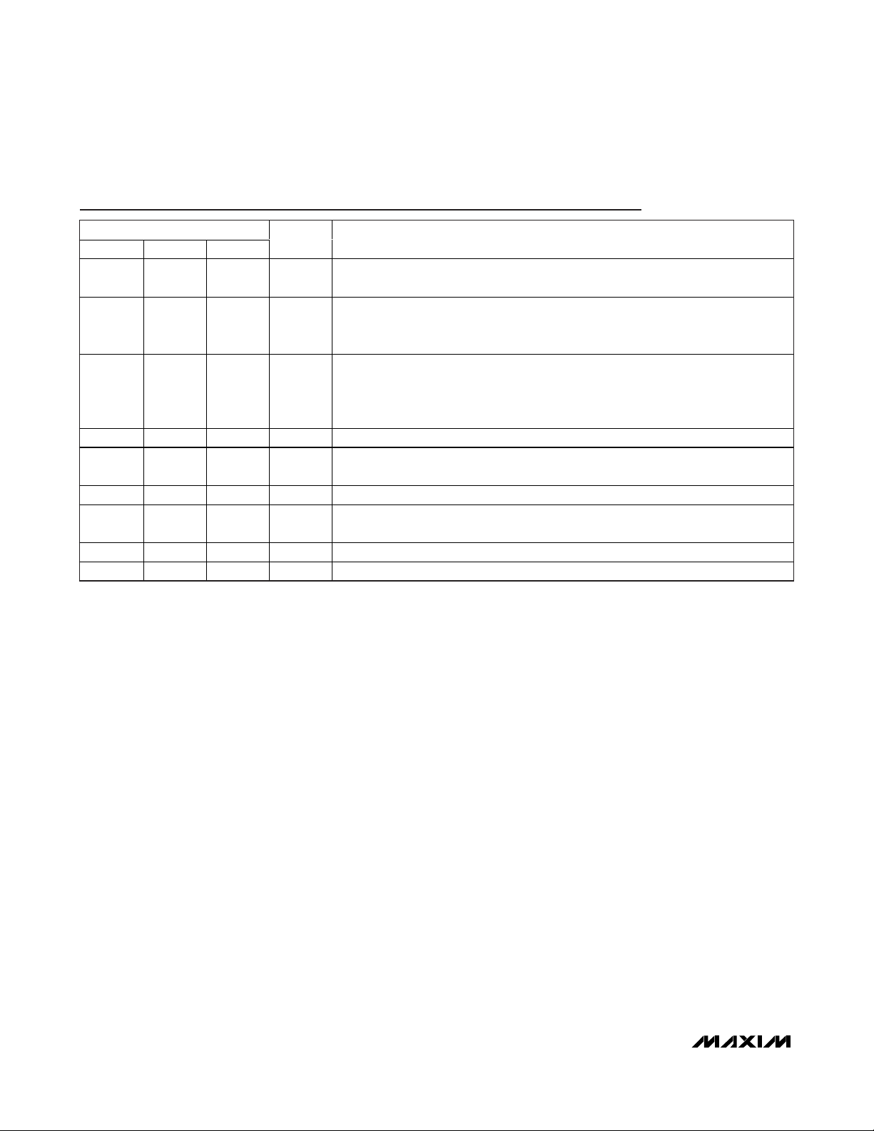
Pin Description
PIN
MAX700 MAX701 MAX702
111MR
2 — — SENSE
NAME FUNCTION
Input for Manual Pushbutton Reset. Has internal 5µA pullup. Low input activates the
RESET/RESET outputs.
The voltage-sense input when CTL = V
remains connected to the internal comparator. So, when V
internally (CTL = GND), SENSE should be left open circuit.
. Its threshold is 1.29V. SENSE always
CC
is being monitored
CC
Normally NOT used when voltage is monitored through V
3 — — HYST
4 4 3 GND Ground
567RESET
6 5 — RESET Inverted Version of RESET
7 — — CTL
882VCCChip Power and +5V Sensing Input (When CTL = GND on MAX700)
— 2, 3, 7 4, 5, 6, 8 N.C. No Connection
monitoring through SENSE (CTL = V
reducing noise and spurious reset activity (Figure 3). HYST turns on 5µs before the
RESET/RESET outputs are activated, and its on-resistance to GND is typically 1kΩ.
Goes low when V
when SENSE falls below 1.29V.
When C TL = GN D , V
and S E N S E i s m oni tor ed , al l ow i ng the thr eshol d to b e set w i th exter nal r esi stor s.
CC
(CTL = GND). When
), HYST allows hysteresis to be added,
CC
falls below 4.65V, or when CTL = VCC on the MAX700 goes low
i s m oni tor ed b y the r eset ci r cui t. When C TL = V
C C
CC
C C
, V
C C
i s i g nor ed
Page 5
MAX700/MAX701/MAX702
Power-Supply Monitor with Reset
_______________________________________________________________________________________ 5
Figure 1. MAX700 Block Diagram
SENSE
Figure 4. Typical MAX700/MAX701/MAX702 RESET Output vs. V
CC
Figure 2. MAX700 Typical Connection Diagram
Figure 3. MAX700 Connected for External Senses and
Hysteresis
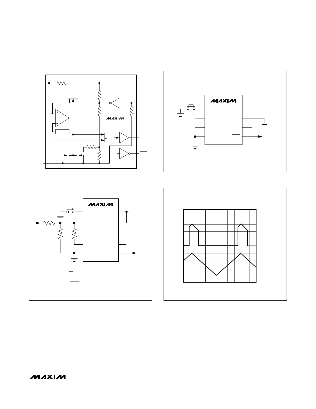
Figure 4 shows the RESET output of the MAX700/
MAX701/MAX702 in the correct state for VCCvoltages
down to 0V. Note the effect of the built-in hysteresis on
the trigger lever of RESET.
Package Information
For the latest package outline information, go to
www.maxim-ic.com/packages.
HYST
GND
1MΩ
1
MR
COMPARATOR
2
1.29V REF
3
4
R
150kΩ
MAX700
OSCRCR
8
7
6
5
V
CC
CTL
RESET
RESET
MANUAL
RESET
BUTTON
N.C.
1
2
3
4
MR
SENSE
HYST
GND
MAX700
V
CTL
RESET
RESET
8
CC
+5V
7
6
N.C.
5
TO µP
MANUAL
RESET
BUTTON
1
MAX700
MR
V
R1
IN
R3 =
2
SENSE
R3R2
3
HYST
4
GND
V
L
V
= LOWER VOLTAGE THRESHOLDR1 = R2(
- 1
L
)
1.29
R1
V
T
VU = UPPER VOLTAGE THRESHOLD
VU - V
L
HYSTERESIS = VU - V
RESET
RESET
L
V
CTL
8
CC
7
6
N.C.
5
V
3V TO 15V
IN
TO µP
RESET
V
CC
1s/div
2V/div
0V
2V/div
0V
Page 6
MAX700/MAX701/MAX702
Power-Supply Monitor with Reset
Maxim cannot assume responsibility for use of any circuitry other than circuitry entirely embodied in a Maxim product. No circuit patent licenses are
implied. Maxim reserves the right to change the circuitry and specifications without notice at any time.
6
_____________________Maxim Integrated Products, 120 San Gabriel Drive, Sunnyvale, CA 94086 408-737-7600
© 2008 Maxim Integrated Products is a registered trademark of Maxim Integrated Products, Inc.
Revision History
REVISION
NUMBER
0 3/90 Initial release —
1 11/05 Added lead-free information to the Ordering Information table. 1
2 12/07 Updated Pin Description table. 4
REVISION
DATE
DESCRIPTION
PAGES
CHANGED
 Loading...