

Page 1
General Description
The MAX6427–MAX6438 are single/dual-level battery monitors with internal hysteresis. These devices are offered with
single (MAX6427/MAX6428/MAX6429, MAX6433/
MAX6434/MAX6435) or dual (MAX6430/MAX6431/
MAX6432, MAX6436/MAX6437/MAX6438) low-battery output indicators, which can be used to indicate three battery
conditions: battery is good (operate system in normal
mode), battery is weak (operate system in low-power
mode), or battery is empty (disable the system).
These devices are ideal for monitoring single lithium-ion
(Li+) cells or multicell alkaline/NiCd/NiMH power supplies.
When the power-supply voltage drops below the specified
low threshold, the low-battery output asserts. When the
voltage rises above the specified high threshold, the lowbattery output is deasserted following a 140ms minimum
timeout period. The timeout period ensures that the supply
voltages have stabilized before power-converter or microprocessor activity is enabled.
The MAX6427–MAX6438 family is available with several
monitoring options. The MAX6427/MAX6428/MAX6429
offer factory-trimmed battery-monitor thresholds, with a single low-battery output. The MAX6430/MAX6431/MAX6432
also feature factory-trimmed thresholds, but have two lowbattery outputs.
The MAX6433–MAX6438 have user-adjustable threshold
voltages permitting the user to select the hysteresis range,
and consequently the sensitivity of the system to noise. A
wide hysteresis range also prevents chattering that can
result due to battery recovery after load removal. Single
low-battery outputs are supplied by the MAX6433/
MAX6434/MAX6435 and dual low-battery outputs by the
MAX6436/MAX6437/MAX6438.
The MAX6427–MAX6438 family is available with three output logic options for convenient interface with system
power circuitry or microprocessors. The family is offered in
small SOT23 and SOT143 packages and is fully specified
over temperature.
________________________Applications
Battery-Powered Systems (Single-Cell Li+ or
Two/Three-Cell NiMH, NiCd, Alkaline)
Cell Phones/Cordless Phones Pagers
Portable Medical Devices PDAs
Electronic Toys MP3 Players
Features
♦ Factory-Trimmed or User-Adjustable Threshold
Options
Factory-Trimmed Low Thresholds from 1.6V to
2.1V or 2.6V to 3.1V in 100mV Increments
(MAX6427–MAX6432)
Factory-Trimmed High Thresholds from 2.3V to
2.6V or 3.3V to 3.6V in 100mV Increments
(MAX6427–MAX6432)
User-Adjustable Low/High Thresholds with
615mV Internal Reference (MAX6433–MAX6438)
♦ Low Current (1µA, typ)
♦ Single or Dual Low-Battery Outputs
♦ Push-Pull LBO, Open-Drain LBO, and Open-Drain
LBO Options
♦ 140ms Minimum LBO Timeout Period
♦ Immune to Short Battery Voltage Transients
♦ Guaranteed Valid LBO Logic State to BATT = 1.0V
♦ -40°C to +85°C Operating Temperature Range
♦ Small 3, 4, 5 and 6-Pin SOT Packages
♦ No External Components Required
(MAX6427–MAX6432)
MAX6427–MAX6438
Low-Power, Single/Dual-Level Battery Monitors
with Hysteresis
________________________________________________________________ Maxim Integrated Products 1
19-2323; Rev 1; 9/03
For pricing, delivery, and ordering information, please contact Maxim/Dallas Direct! at
1-888-629-4642, or visit Maxim’s website at www.maxim-ic.com.
Ordering Information
Typical Operating Circuit appears at end of data sheet.
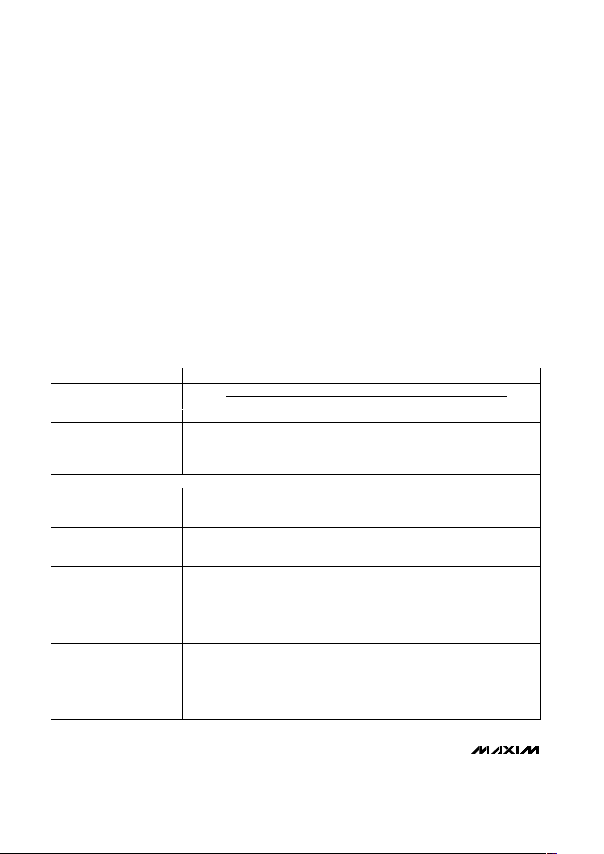
PART TEMP RANGE PIN-PACKAGE
MAX6427_ _UR-T -40°C to +85°C 3 SOT23-3
Ordering Information continued at end of data sheet.
Pin Configurations continued at end of data sheet.
†
The MAX6427–MAX6432 are available with factory-trimmed
battery-monitor thresholds. Select the desired thresholds
using Tables 1 or 2 and enter the corresponding letters in
the part number by replacing “_ _”.
Note: There are 26 standard versions with a required order
minimum of 2500 pieces. Sample stock is generally held on
the standard versions only (see Standard Versions Table).
Required order increment is 10,000 pieces for nonstandard
versions. Contact factory for availability. All devices available in tape-and-reel only.
BATT
1
3 GND
( ) ARE FOR THE MAX6429.
MAX6427
MAX6428
MAX6429
SOT23-3
TOP VIEW
2
LBO
(LBO)
Pin Configurations
Page 2
MAX6427–MAX6438
Low-Power, Single/Dual-Level Battery Monitors
with Hysteresis
2 _______________________________________________________________________________________
ABSOLUTE MAXIMUM RATINGS
ELECTRICAL CHARACTERISTICS
(BATT = 1.0V to 5.5V or VDD= 1.6V to 5.5V, TA= -40°C to +85°C, unless otherwise specified. Typical values are at TA= +25°C.)
(Note 1)
Stresses beyond those listed under “Absolute Maximum Ratings” may cause permanent damage to the device. These are stress ratings only, and functional
operation of the device at these or any other conditions beyond those indicated in the operational sections of the specifications is not implied. Exposure to
absolute maximum rating conditions for extended periods may affect device reliability.
BATT, VDDto GND ................................................-0.3V to +6.0V
HTHIN, LTHIN Inputs to GND.....................-0.3V to (V
DD
+ 0.3V)
Open-Drain LBO/LBO, LBOH/LBOH,
LBOL/LBOL to GND .........................................-0.3V to +6.0V
Push-Pull LBO/LBO, LBOH/LBOH,
LBOL/LBOL to GND ................-0.3V to (BATT or V
DD
+ 0.3V)
Input Current (all pins) ........................................................20mA
Output Current (all pins) .....................................................20mA
Continuous Power Dissipation (T
A
= +70°C)
3-Pin SOT23-3 (derate 4.0mW/°C above +70°C) .......320mW
4-Pin SOT143-4 (derate 4.0mW/°C above +70°C) .....320mW
5-Pin SOT23-5 (derate 7.1mW/°C above +70°C) .......571mW
6-Pin SOT23-6 (derate 8.7mW/°C above +70°C) .......696mW
Operating Temperature Range ...........................-40°C to +85°C
Junction Temperature......................................................+150°C
Storage Temperature Range .............................-65°C to +150°C
Lead Temperature (soldering, 10s) .................................+300°C
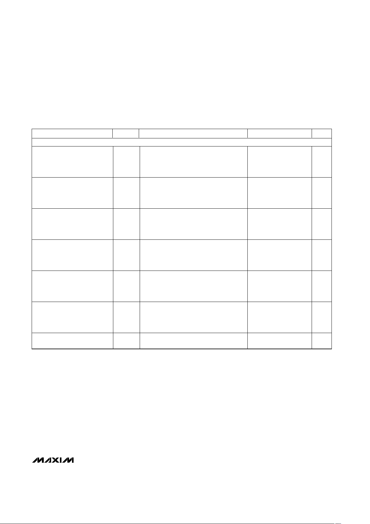
PARAMETER SYMBOL CONDITIONS MIN TYP MAX UNITS
TA = -40°C to +85°C
1.2 5.5
Operating Voltage Range V
BATT
TA = 0°C to +70°C
1.0 5.5
V
Operating Voltage Range V
DD
TA = -40°C to +85°C 1.6 5.5 V
BATT Supply Current I
BATT
V
BATT
= 3.7V, no load (MAX6427–MAX6432) 1 1.5 µA
VDD Supply Current I
DD
V
DD
= 3.7V, no load
(MAX6433–MAX6438)
1 1.5 µA
FACTORY-FIXED THRESHOLDS (MAX6427–MAX6432)
HTH Threshold
(Note 2)
V
HTH
Factory-fixed options, BATT rising,
LBO deasserted when BATT rises above
V
HTH
(MAX6427/MAX6428/MAX6429)
-2.5 +2.5 %
LTH Threshold
(Note 2)
V
LTH
Factory-fixed options, BATT falling,
LBO asserted when BATT falls below V
LTH
(MAX6427/MAX6428/MAX6429)
-2.5 +2.5 %
HTH- Threshold
(Note 2)
V
HTH-
Factory-fixed options, BATT falling, LBOH
asserted when BATT falls below V
HTH-
(MAX6430/MAX6431/MAX6432)
-2.5 +2.5 %
HTH+ Threshold
(Note 3)
V
HTH+
Factory-fixed options, BATT rising,
LBOH deasserted when BATT rises above
V
HTH+
(MAX6430/MAX6431/MAX6432)
-2.5 +2.5 %
LTH- Threshold
(Note 2)
V
LTH-
Factory-fixed options, BATT falling,
LBOL asserted when BATT falls below V
LTH-
(MAX6430/MAX6431/MAX6432)
-2.5 +2.5 %
LTH+ Threshold
(Note 3)
V
LTH+
Factory-fixed options, BATT rising,
LBOL deasserted when BATT rises above
V
LTH+
(MAX6430/MAX6431/MAX6432)
-2.5 +2.5 %
Page 3
MAX6427–MAX6438
Low-Power, Single/Dual-Level Battery Monitors
with Hysteresis
_______________________________________________________________________________________ 3
ELECTRICAL CHARACTERISTICS (continued)
(BATT = 1.0V to 5.5V or VDD= 1.6V to 5.5V, TA= -40°C to +85°C, unless otherwise specified. Typical values are at TA= +25°C.)
(Note 1)
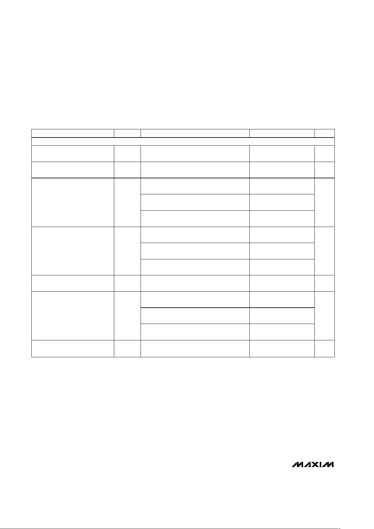
PARAMETER SYMBOL CONDITIONS MIN TYP MAX UNITS
USER-ADJUSTABLE THRESHOLDS (MAX6433–MAX6438)
HTHIN Threshold
(Note 4)
V
HTHIN
User-adjustable options, HTHIN rising,
LBO is deasserted when HTHIN rises above
V
HTHIN-
, V
REF
= 615mV
(MAX6433/MAX6434/MAX6435)
-2.5 +2.5 %
LTHIN Threshold
(Note 4)
V
LTHIN
User-adjustable options, LTHIN falling,
LBOH is asserted when LTHIN falls below
V
LTHIN-
, V
REF
= 615mV
(MAX6433/MAX6434/MAX6435)
-2.5 +2.5 %
HTHIN+ Threshold
(Note 4)
V
HTHIN+
User-adjustable options, HTHIN rising,
LBOH is deasserted when HTHIN rises
above V
HTHIN+
, V
REF
= 615mV
(MAX6436/MAX6437/MAX6438)
-2.5 +2.5 %
HTHIN- Threshold
(Note 5)
V
HTHIN-
User-adjustable options, HTHIN falling,
LBOH is asserted when HTHIN falls below
V
HTHIN-
, V
REF
= 585mV
(MAX6436/MAX6437/MAX6438)
-2.5 +2.5 %
LTHIN+ Threshold
(Note 4)
V
LTHIN+
User-adjustable options, LTHIN rising,
LBOL is deasserted when LTHIN rises
above V
LTHIN+
, V
REF
= 615mV
(MAX6436/MAX6437/MAX6438)
-2.5 +2.5 %
LTHIN- Threshold
(Note 5)
V
LTHIN-
User-adjustable options, LTHIN falling,
LBOL is asserted when LTHIN falls below
V
LTHIN-
, V
REF
= 585mV
(MAX6436/MAX6437/MAX6438)
-2.5 +2.5 %
HTHIN/LTHIN Leakage Current
(Note 6)
I
LKG
V
HTHIN
or V
LTHIN
> 400mV 20 nA
Page 4
MAX6427–MAX6438
Low-Power, Single/Dual-Level Battery Monitors
with Hysteresis
4 _______________________________________________________________________________________
Note 1: Production testing done at TA= +25°C, limits over temperature guaranteed by design only.
Note 2: Percentage of selected factory-fixed HTH- or LTH- threshold voltage.
Note 3: Percentage of 1.05
✕
(selected factory-fixed threshold voltage).
Note 4: Percentage of 615mV voltage reference.
Note 5: Percentage of 585mV voltage reference.
Note 6: Guaranteed by design.
Note 7: V
SUPPLY
is BATT or VDD.
ELECTRICAL CHARACTERISTICS (continued)
(BATT = 1.0V to 5.5V or VDD= 1.6V to 5.5V, TA= -40°C to +85°C, unless otherwise specified. Typical values are at TA= +25°C.)
(Note 1)
PARAMETER SYMBOL CONDITIONS MIN TYP MAX UNITS
LOW-BATTERY OUTPUTS (LBO, LBO, LBOH, LBOH, LBOL, LBOL )
Timeout Period t
LBOP
BATT or VDD/HTHIN/LTHIN rising above
threshold
140 210 280 ms
Delay t
LBOD
BATT or VDD/HTHIN/LTHIN falling below
threshold
100 µs
BATT or V
DD
≥ 1.6V, I
SINK
= 100µA,
asserted low
0.3
BATT or V
DD
≥ 2.7V, I
SINK
= 1.2mA,
asserted low
0.3
LBO/LBOL/LBOH Output LOW
(Push-Pull or Open-Drain)
V
OL
BATT or V
DD
≥ 4.5V, I
SINK
= 3.2mA,
asserted low
0.4
V
BATT or V
DD
≥ 1.6V, I
SOURCE
= 200µA,
deasserted
0.8 × V
SUPPLY
BATT or V
DD
≥ 2.7V, I
SOURCE
= 500µA,
deasserted
0.8 × V
SUPPLY
LBO Output HIGH (Push-Pull
Only) (Note 7)
V
OH
BATT or V
DD
≥ 4.5V, I
SOURCE
= 800µA,
deasserted
0.8 × V
SUPPLY
V
LBO Output Leakage Current
(Open-Drain Only)
I
LKG
LBO deasserted 500 nA
BATT or V
DD
≥ 1.6V, I
SINK
= 100µA,
deasserted low
0.3
BATT or V
DD
≥ 2.7V, I
SINK
= 1.2mA,
deasserted low
0.3
LBO/LBOL/LBOH Output
LOW (Open-Drain Only)
V
OL
BATT or V
DD
≥ 4.5V, I
SINK
= 3.2mA,
deasserted low
0.4
V
LBO Output Leakage Current
(Open-Drain Only)
I
LKG
LBO asserted 500 nA
Page 5
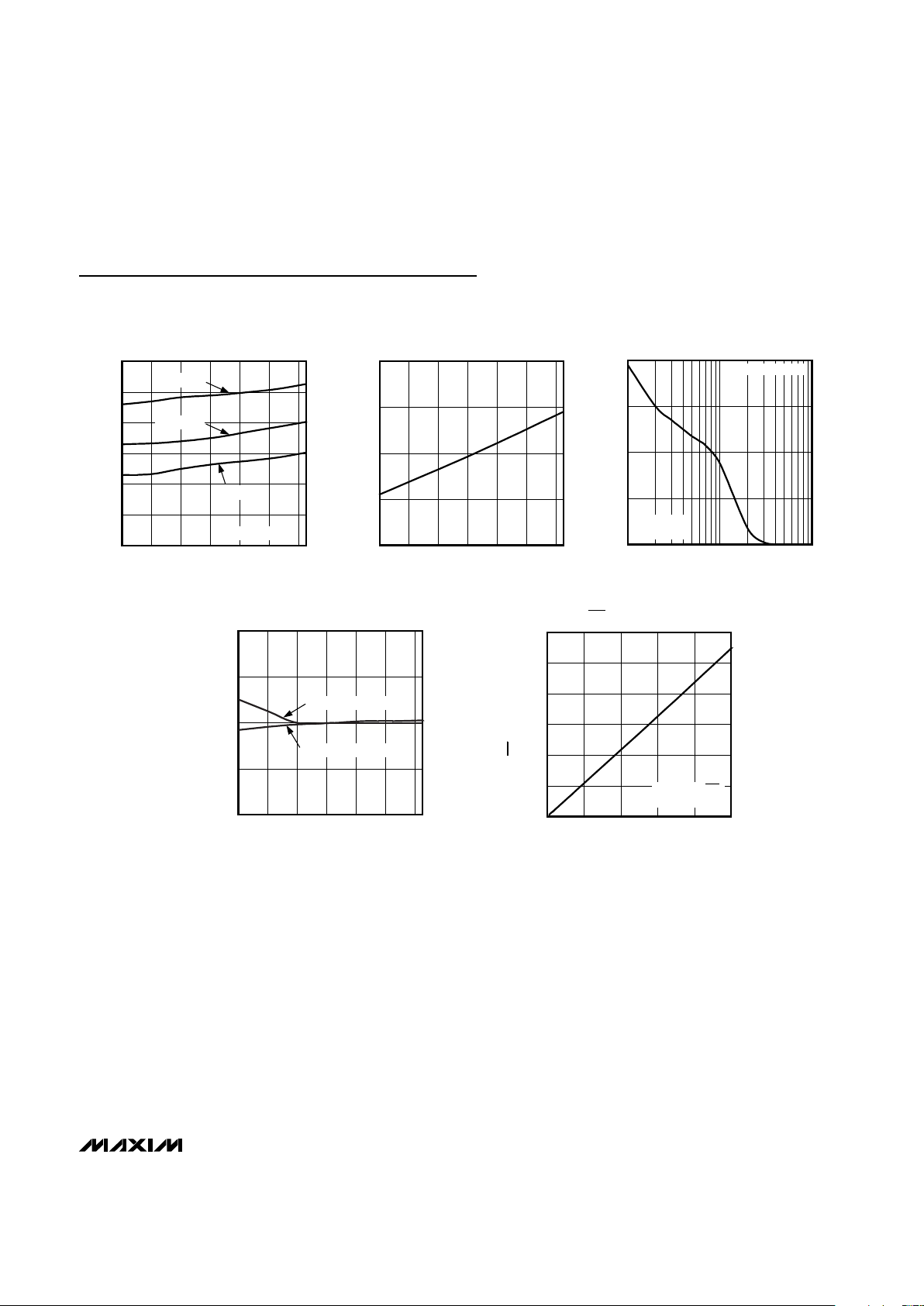
0
0.6
0.3
1.2
0.9
1.5
1.8
-40 20 40-20 0 60 80
SUPPLY CURRENT
vs. TEMPERATURE
MAX6427 toc01
TEMPERATURE (°C)
SUPPLY CURRENT (µA)
V
BATT
= 5V
V
BATT
= 3.3V
V
BATT
= 2V
LBO NOT ASSERTED
1.010
1.005
1.000
0.995
0.990
-40 20-20 0 40 60 80
NORMALIZED LBO TIMEOUT PERIOD
vs. TEMPERATURE
MAX6427 toc02
TEMPERATURE (°C)
NORMALIZED LBO TIMEOUT PERIOD
80
60
40
20
0
10 100 1000
MAXIMUM TRANSIENT DURATION
vs. LBO COMPARATOR OVERDRIVE
MAX6427 toc03
LBO COMPARATOR OVERDRIVE (mV)
MAXIMUM TRANSIENT DURATION (µs)
OUTPUT DOES
NOT ASSERT
OUTPUT ASSERTS
0.950
0.975
1.025
1.000
1.050
-40 0-20 20 40 60 80
NORMALIZED UPPER AND LOWER
TRIP VOLTAGES vs. TEMPERATURE
MAX6427 toc04
TEMPERATURE (°C)
NORMALIZED TRIP VOLTAGES (V)
LOWER TRIP VOLTAGE
UPPER TRIP VOLTAGE
0
100
50
200
150
250
300
010
MAX6427 toc05
I
SINK
(mA)
4268
LBO OUTPUT vs. I
SINK
LBO OUTPUT (mV)
OPEN-DRAIN LBO
ASSERTED
MAX6427–MAX6438
Low-Power, Single/Dual-Level Battery Monitors
with Hysteresis
_______________________________________________________________________________________ 5
Typical Operating Characteristics
(TA = +25°C, unless otherwise noted.)
Page 6
MAX6427–MAX6438
Low-Power, Single/Dual-Level Battery Monitors
with Hysteresis
6 _______________________________________________________________________________________
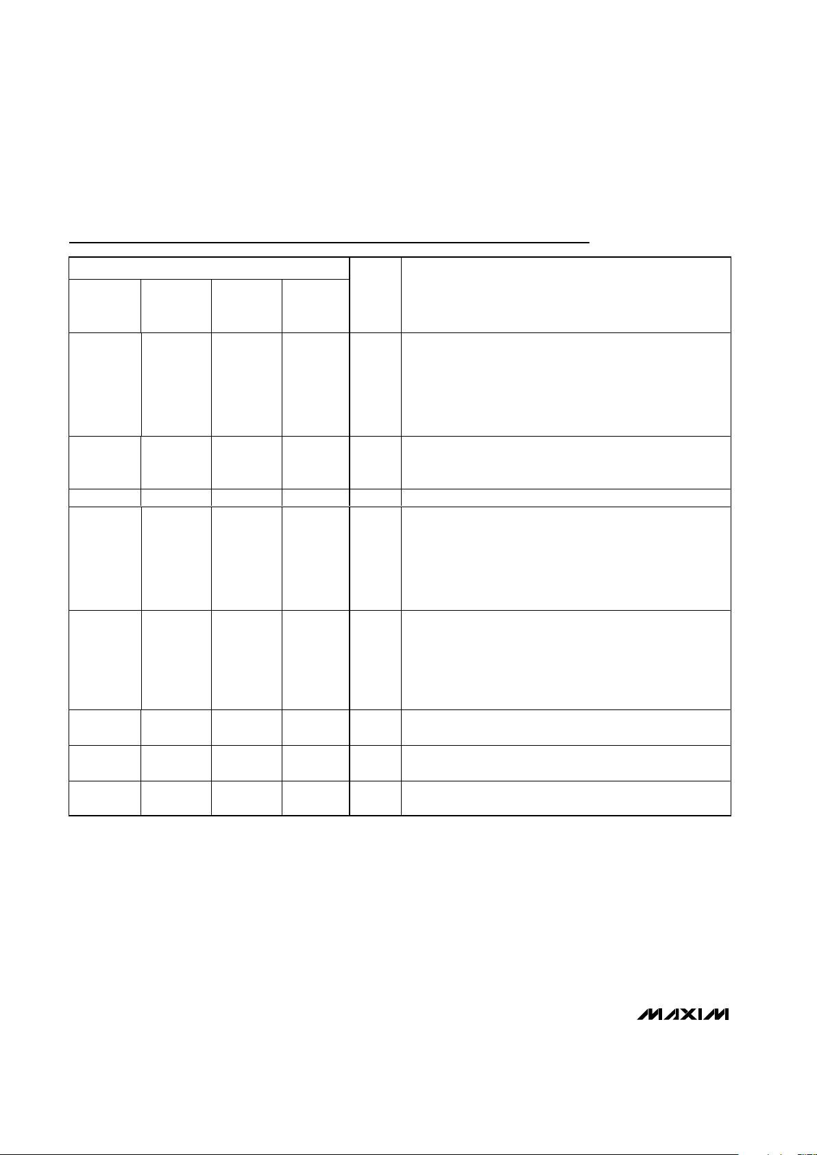
Pin Description
PIN
M AX6427/
M AX6428/
M AX6429
M AX6430/
M AX6431/
M AX6432
M AX6433/
M AX6434/
M AX6435
M AX6436/
M AX6437/
M AX6438
NAME FUNCTION
1 — 4 —
LBO/
LBO
Low-Battery Output. LBO/LBO is asserted when BATT drops
below V
LTH
(MAX6427/MAX6428/MAX6429) or when LTHIN
(MAX6433/MAX6434/MAX6435) drops below V
LTHIN
, and
remains asserted for at least 140ms after BATT exceeds V
HTH
(MAX6427/MAX6428/MAX6429) or V
HTHIN
(MAX6433/
MAX6434/MAX6435).
23——BATT
Battery-Voltage Input. Input for battery-voltage threshold
monitors and device power supply for factory-trimmed
threshold versions.
3 1 2 2 GND Ground
— 2 — 5
LBOH/
LBOH
Low-Battery Output High. LBOH/LBOH is asserted when BATT
drops below V
HTH-
(MAX6430/MAX6431/MAX6432) or when
HTHIN drops below V
HTHIN-
(MAX6436/MAX6437/ MAX6438). It
remains asserted for at least 140ms after BATT exceeds V
HTH+
(MAX6430/MAX6431/MAX6432) or HTHIN rises above V
HTHIN+
(MAX6436/MAX6437/MAX6438).
— 4 — 4
LBOL/
LBOL
Low-Battery Output Low. LBOL/LBOL is asserted when BATT
drops below V
LTH-
(MAX6430/MAX6431/MAX6432) or when
LTHIN drops below V
LTHIN-
(MAX6436/MAX6437/
MAX6438). It remains asserted for at least 140ms after BATT
exceeds V
LTH+
(MAX6430/MAX6431/MAX6432) or LTHIN rises
above V
LTHIN+
(MAX6436/MAX6437/MAX6438).
—— 1 1 HTHIN
HTH Threshold Monitor Input. A resistor-divider network sets
the high threshold associated with LBOH/LBOH.
—— 3 3 LTHIN
LTH Threshold Monitor Input. A resistor-divider network sets
the low threshold associated with LBOL/LBOL.
—— 56V
DD
VDD Supply Voltage Input. Device power supply for adjustable
threshold versions.
Page 7

MAX6427–MAX6438
Low-Power, Single/Dual-Level Battery Monitors
with Hysteresis
_______________________________________________________________________________________ 7
Detailed Description
The MAX6427–MAX6438 family is available with several
monitoring options. The MAX6427/MAX6428/MAX6429
offer factory-trimmed battery-monitor thresholds, with a
single low-battery output (see Figure 1). The
MAX6430/MAX6431/MAX6432 also feature factorytrimmed thresholds, but have two low-battery outputs
(see Figure 2). The factory-trimmed thresholds of the
MAX6427–MAX6432 eliminate the requirement for
external components.
The user sets the threshold voltages for the
MAX6433–MAX6438, which permit the user to select
the hysteresis range, and consequently the sensitivity
of the system to noise. A wide hysteresis range prevents chattering that can result during battery recovery
or load removal. The MAX6433/MAX6434/ MAX6435
have single low-battery outputs and the MAX6436/
MAX6437/MAX6438 have dual low-battery outputs (see
Figures 3 and 4).
The MAX6427–MAX6438 combine a 615mV reference
with two comparators, logic, and timing circuitry to provide the user with information about the charge state of
the power-supply batteries. The MAX6427–MAX6438
monitor separate high-voltage and low-voltage thresholds to determine battery status. The output(s) can be
used to signal when the battery is charged, when the
battery is low, and when the battery is empty. Factory-
trimmed thresholds are ideal for monitoring single-cell
Li+ or multicell alkaline/NiCd/NiMH power supplies.
User-programmable versions are also available with
thresholds determined using an external resistordivider (see Resistor-Value Selection).The adjustable
versions can monitor down to 0.62V, making them suitable for monitoring single-cell alkaline, NiMH, and NiCd
applications (V
DD
≥ 1.6V).
When the power-supply voltage drops below the specified low threshold, the low-battery output asserts (see
Low-Battery Output). When the voltage rises above the
specified high threshold following a 140ms (min) timeout period, the low-battery output is deasserted (see
Threshold Monitoring). This ensures the supply voltage
has stabilized before power-converter or microprocessor activity is enabled.
Low-Battery Output
The low-battery outputs are available in active-low
(LBO, LBOH, LBOL, push-pull and open-drain) and
active-high (LBO, LBOL, LBOH, open-drain) configurations. Push-pull outputs are referenced to BATT (for
factory-trimmed versions) or VDD(for adjustable threshold versions).
The open-drain devices can be pulled to a voltage independent of VDDor BATT, up to 5.5V. This allows the
R
S
Q
LBO TIMEOUT
PERIOD
V
BATT
V
BATT
( ) ARE FOR THE MAX6429
615
mV
+
-
Q
LBO
(LBO)
Figure 1. MAX6427/MAX6428/MAX6429 Functional Diagram
Page 8

MAX6427–MAX6438
Low-Power, Single/Dual-Level Battery Monitors
with Hysteresis
8 _______________________________________________________________________________________
device to monitor and operate from direct battery voltage
while interfacing to higher voltage microprocessors.
The MAX6427/MAX6428/MAX6429/MAX6433/MAX6434/
MAX6435 single-output voltage monitors provide a single low-battery output, LBO/LBO. The MAX6427/
MAX6428/MAX6429 fixed-threshold parts assert
LBO/LBO when BATT drops below V
LTH
. The
MAX6433/MAX6434/MAX6435 adjustable-threshold
parts assert LBO/LBO when the LTHIN input drops
below the V
LTHIN
threshold (615mV) (see Figure 5).
The MAX6430/MAX6431/MAX6432/MAX6436/MAX6437/
MAX6438 dual-output voltage monitors provide two lowbattery outputs, LBOH/LBOH and LBOL/LBOL. The
MAX6430/MAX6431/MAX6432 fixed-threshold parts
assert LBOH/LBOH when BATT drops below V
HTH-
,
and assert LBOL/LBOL when BATT drops below V
LTH-
.
The MAX6436/MAX6437/MAX6438 adjustable-threshold parts assert LBOH/LBOH when HTHIN drops below
V
HTHIN-
, and assert LBOL/LBOL when LTHIN drops
below V
LTHIN-
(see Figure 6).
Threshold Monitoring
The MAX6433–MAX6438 HTHIN and LTHIN inputs are
high-impedance inputs to comparators. An external resistor-divider network is required between the monitored
voltage, HTHIN, LTHIN, and GND to select the desired
thresholds (see Resistor-Value Selection). The
MAX6433/MAX6434/MAX6435 single-output voltage
monitors assert LBO/LBO when LTHIN drops below the
internal LTHIN reference (615mV). LBO/LBO is deasserted when HTHIN rises above the internal HTHIN reference
level (615mV) for at least 140ms (see Figure 6).
The MAX6436/MAX6437/MAX6438 dual-output voltage
monitors assert LBOL/LBOL when LTHIN drops below
the LTHIN- threshold and deassert LBOL/LBOL when
LTHIN rises above the LTHIN+ threshold for at least
140ms. LBOH/LBOH is asserted when HTHIN drops
below the HTHIN- threshold and is deasserted when
HTHIN rises above the HTHIN+ threshold for at least
140ms (see Figure 7).
(LBOL)
LBO
TIMEOUT
PERIOD
( ) ARE FOR THE MAX6432
HYSTERESIS SWITCH
HYSTERESIS SWITCH
V
BATT
V
BATT
615
mV
LBOL
LBOH
(LBOH)
+
-
Figure 2. MAX6430/MAX6431/MAX6432 Functional Diagram
Page 9

MAX6427–MAX6438
Low-Power, Single/Dual-Level Battery Monitors
with Hysteresis
_______________________________________________________________________________________ 9
Hysteresis
Hysteresis increases the comparator’s noise margin by
increasing the upper threshold or decreasing the lower
threshold (see Figure 8). The hysteresis prevents the
output from oscillating (chattering) when BATT or V
DD
is near the low-battery threshold. This is especially
important for applications where the load on the battery
creates significant fluctuations in battery voltages.
Fixed Hysteresis (MAX6427–MAX6432)
The MAX6427/MAX6428/MAX6429 total hysteresis is the
difference between the factory-trimmed V
LTH
and V
HTH.
For the MAX6430/MAX6431/MAX6432, the total hysteresis
is the difference between the factory-trimmed V
HTH-
and
V
HTH+
or V
LTH-
and V
LTH+
values, approximately 5%.
Adjustable Hysteresis (MAX6433–MAX6438)
Figure 7 shows the correct connections for the external
resistor-dividers. To adjust the low-battery threshold
and hysteresis connect resistor R1 between V
DD
and
LTHIN, resistor R2 between LTHIN and HTHIN, and R3
between HTHIN and GND. The hysteresis for the
MAX6433–MAX6438 is determined by an external resistor-divider network (see Resistor-Value Selection sec-
tion of Applications Information). The hysteresis for the
MAX6436/MAX6437/MAX6438 is the differences
between V
HTHIN-
and V
HTHIN+
(~5%) or V
LTHIN-
and
V
LTHIN+
(~5%).
R
QS
Q
LBO TIMEOUT
PERIOD
V
BATT
V
DD
LTHIN
HTHIN
( ) ARE FOR THE MAX6435
EXTERNAL
RESISTOR-
DIVIDER
615
mV
V
DD
LBO
(LBO)
+
-
Figure 3. MAX6433/MAX6434/MAX6435 Functional Diagram
Page 10

MAX6427–MAX6438
Low-Power, Single/Dual-Level Battery Monitors
with Hysteresis
10 ______________________________________________________________________________________
(LBOL)
LBO
TIMEOUT
PERIOD
( ) ARE FOR THE MAX6438
(LBOH)
HYSTERESIS SWITCH
HYSTERESIS SWITCH
V
BATT
LTHIN
HTHIN
V
BATT
615
mV
V
DD
LBOL
LBOH
+
-
Figure 4. MAX6436/MAX6437/MAX6438 Functional Diagram
V
BATT
V
HTH
V
LTH
LBO
t
LBOP
t
LBOP
Figure 5. Single Low-Battery Output Timing
Page 11

MAX6427–MAX6438
Low-Power, Single/Dual-Level Battery Monitors
with Hysteresis
______________________________________________________________________________________ 11
V
BATT
V
HTH+
V
HTH-
V
LTH+
V
LTH-
LBOH
LBOL
t
LBOP
t
LBOP
t
LBOP
t
LBOP
Figure 6. Dual Low-Battery Output Timing
MAX6433
V
DD
V
DD
LTHIN
HTHIN GND
R1
R2
R3
LBO
LBO
Figure 7. Adjustable Threshold Selection
V
BATT
LBO
t
LBOP
V
HTH
V
LTH
V
HYST
HTH = BATTERY VOLTAGE GOOD, ENABLE OPERATION.
LTH = BATTERY VOLTAGE LOW, SUSPEND/DISABLE OPERATION.
Figure 8. Hysteresis
Page 12

MAX6427–MAX6438
Low-Power, Single/Dual-Level Battery Monitors
with Hysteresis
12 ______________________________________________________________________________________
Applications Information
Resistor-Value Selection (Programming
the Adjustable Thresholds)
MAX6433/MAX6434/MAX6435
(See Figure 5)
Use the following steps to determine values for R1, R2,
and R3 of Figure 8.
1) Choose a value for R
TOTAL
, the sum of R1, R2, and
R3. Because the MAX6433/MAX6434/MAX6435
have very high input impedances, R
TOTAL
can be
up to 5MΩ.
2) Calculate R3 based on R
TOTAL
and the desired
upper trip point:
3) Calculate R2 based on R
TOTAL
, R3, and the
desired lower trip point:
4) Calculate R1 based on R
TOTAL
, R3, and R2:
MAX6436/MAX6437/MAX6438
(See Figure 6)
Use the following steps to determine values for R1, R2,
and R3 of Figure 8.
1) Choose a value for R
TOTAL
, the sum of R1, R2, and
R3. Because the MAX6436/MAX6437/MAX6438
have very high input impedances, R
TOTAL
can be
up to 5MΩ.
2) Calculate R3 based on R
TOTAL
and the desired
upper trip point:
3) Calculate R2 based on R
TOTAL
, R3, and the
desired lower trip point:
4) Calculate R1 based on R
TOTAL
, R3, and R2:
V
HTH+
= V
HTH-
✕ 1.05, V
LTH+
= V
LTH-
✕ 1.05
DC-to-DC Converter Application
The MAX6430/MAX6431/MAX6432 and MAX6436/
MAX6437/MAX6438 dual-output battery monitors can
be used in conjunction with a step-up DC-to-DC converter to power 5V microprocessor systems using a single Li+ cell or two to three alkaline/NiCd/NiMH cells
(Figure 9). The LBOH output indicates that the battery
voltage is weak, and is used to warn the microprocessor of potential problems. Armed with this information
the microprocessor can reduce system power consumption. The LBOL output indicates the battery is
empty, and system power should be disabled. By connecting LBOL to the SHDN pin of the DC-to-DC converter, power to the microprocessor is removed.
RR RR
TOTAL
123 = −−
5853mV R
V
R
TOTAL
TRIPLOW
×
−
R
VR
V
mV R
V
REF TOTAL
TRIPHIGH
TOTAL
TRIPHIGH
3
585
=
×
=
×
VV V mV
LBOL OUTPUT
VVV
RR R
RR
LBOH OUTPUT
VVV
RR R
R
RRRR
REF LTHI HTHIN
TRIPLOW LTH REF
TRIPHIGH REF
TOTAL
/:
/:
===
==
++
+
==
++
=+ +
N- -
-
HTL-
585
12 3
23
12 3
3
12 3
LBOL
LBOH
RR RR
TOTAL
123 = −−
R
mV R
V
R
TOTAL
TRIPLOW
2
6153=×
−
R
VR
V
mV R
V
REF TOTAL
TRIPHIGH
TOTAL
TRIPHIGH
3
585
=
×
=
×
VV V mV
VVV
RR R
RR
VVV
RR R
R
RRRR
REF LTHIN HTHIN
TRIPLOW LTH REF
TRIPHIGH HTL REF
TOTAL
===
==
++
+
==
++
=+ +
615
12 3
23
12 3
3
12 3
Figure 9. DC-to-DC Converter Application
µP
V
BATT
NMI
V
CC
DC/DC
BATT
OUT
IN
MAX6431
LBOL
LBOH
SHDN
GND GND
Page 13

MAX6427–MAX6438
Low-Power, Single/Dual-Level Battery Monitors
with Hysteresis
______________________________________________________________________________________ 13
Microprocessor power will not return until the battery has
recharged to a voltage greater than HTH+ (Figure 6).
Li+ Battery Charger Application
The MAX6430/MAX6431/MAX6432 and MAX6436/
MAX6437/MAX6438 dual-output battery monitors can
be used in conjunction with a battery charger to provide a system with additional information about the battery charge state (Figure 10). Many battery chargers,
such as the MAX1879, provide the user with a CHG
output, which tells the system that the battery is
charged. The MAX6430/MAX6431/MAX6432 and
MAX6436/MAX6437/MAX6438 dual-output battery mon-
itors provide two outputs, which can be used to relay
the battery condition to the system. This information is
useful in determining which system resources can be
powered by the battery at the current charge state.
Figure 10. Lithium-Ion Cell Charger Application (using MAX1879)
BATT
GND
1-CELL
Li+
BATTERY
THERM ADJ
GATE
CURRENT-
LIMITED
AC WALL
ADAPTER
PULSE-WIDTH
SELECT INPUT
CHG
LED
THERMISTOR
IN
MAX1879 MAX6430
TSEL
GND
LBOL
LBOH
V
BATT
MAX6427
V
BATT
µP
BATT
V
CC
LBO
NMI
Typical Operating Circuit
Page 14

MAX6427–MAX6438
Low-Power, Single/Dual-Level Battery Monitors
with Hysteresis
14 ______________________________________________________________________________________
Chip Information
TRANSISTOR COUNT: 905
PROCESS TECHNOLOGY: BiCMOS
†
The MAX6427–MAX6432 are available with factory-trimmed
battery-monitor thresholds. Select the desired thresholds
using Tables 1 or 2 and enter the corresponding letters in
the part number by replacing “_ _”.
Note: There are 26 standard versions with a required order
minimum of 2500 pieces. Sample stock is generally held on
the standard versions only (see Standard Versions Table).
Required order increment is 10,000 pieces for nonstandard
versions. Contact factory for availability. All devices available in tape-and-reel only.
Ordering Information (continued)
PART TEMP RANGE PIN-PACKAGE
MAX6428_ _UR-T -40°C to +85°C 3 SOT23-3
MAX6429_ _UR-T -40°C to +85°C 3 SOT23-3
MAX6430_ _US-T -40°C to +85°C 4 SOT143-4
MAX6431_ _US-T -40°C to +85°C 4 SOT143-4
MAX6432_ _US-T -40°C to +85°C 4 SOT143-4
MAX6433UK-T -40°C to +85°C 5 SOT23-5
MAX6434UK-T -40°C to +85°C 5 SOT23-5
MAX6435UK-T -40°C to +85°C 5 SOT23-5
MAX6436UT-T -40°C to +85°C 6 SOT23-6
MAX6437UT-T -40°C to +85°C 6 SOT23-6
MAX6438UT-T -40°C to +85°C 6 SOT23-6
Pin Configurations (continued)
1
2
4
3 BATT
( ) ARE FOR THE MAX6432
LBOH
(LBOH)
GND
MAX6430
MAX6431
MAX6432
SOT143-4
LBOL
(LBOL)
GND
LBO
(LBO)
LTHIN
( ) ARE FOR THE MAX6435
15V
DD
HTHIN
MAX6433
MAX6434
MAX6435
SOT23-5
2
34
GND
LBOL
(LBOL)
LTHIN
16V
DD
5 LBOH
(LBOH)
HTHIN
MAX6436
MAX6437
MAX6438
SOT23-6
2
34
( ) ARE FOR THE MAX6438
Page 15

MAX6427–MAX6438
Low-Power, Single/Dual-Level Battery Monitors
with Hysteresis
______________________________________________________________________________________ 15
UPPER THRESHOLD (HTH/HTH-)
VOLTAGES 3.3V 3.4V 3.5V 3.6V
2.6V
AG AH AI AJ
2.7V
BG BH BI BJ
2.8V
CG CH CI CJ
2.9V
DG DH DI DJ
3.0V
EG EH EI EJ
3.1V FG FH FI FJ
Table 1. Factory-Trimmed Lower and Upper Threshold Combinations for Single-Cell Li+
or Three-Cell Alkaline/NiCd/NiMH Applications (MAX6427–MAX6432)
UPPER THRESHOLD (HTH/HTH-)
VOLTAGES 2.3V 2.4V 2.5V 2.6V
1.6V KQ KR KS KT
1.7V LQ LR LS LT
1.8V MQ MR MS MT
1.9V NQ NR NS NT
2.0V OQ OR OS OT
2.1V PQ PR PS PT
PART TOP MARK
MAX6427DH FZKZ
MAX6427EH FZLA
MAX6427EI FZLB
MAX6427MR FZLF
MAX6427OR FZLG
MAX6428DH FZLC
MAX6428EH FZLD
MAX6428EI FZLE
MAX6428MR FZLH
MAX6428OR FZLI
MAX6430DH KAEP
MAX6430EH KAEQ
MAX6430EI KAER
Table 2. Factory-Trimmed Lower and Upper Threshold Combinations for Two-Cell
Alkaline/NiCd/NiMH Applications (MAX6427–MAX6432)
LOWER THRESHOLD
(LTH/LTH-)
LOWER THRESHOLD
(LTH/LTH-)
Standard Versions
PART TOP MARK
MAX6430MR KAEL
MAX6430OR KAEM
MAX6431DH KAES
MAX6431EH KAET
MAX6431EI KAEU
MAX6431MR KAEN
MAX6431OR KAEO
MAX6433UK ADVH
MAX6434UK ADVI
MAX6435UK ADVJ
MAX6436UT ABAB
MAX6437UT ABAC
MAX6438UT ABAD
Page 16

MAX6427–MAX6438
Low-Power, Single/Dual-Level Battery Monitors
with Hysteresis
16 ______________________________________________________________________________________
Selector Guide
PART
FACTORY-
FIXED
THRESHOLDS
USER-
ADJUSTABLE
THRESHOLDS
ACTIVE-
LOW PUSH-
PULL
OUTPUT
ACTIVE-
LOW OPEN-
DRAIN
OUTPUT
ACTIVE-
HIGH OPEN-
DRAIN
OUTPUT
SINGLE
OUTPUT
DUAL
OUTPUT
MAX6427 — —— —
MAX6428 —— — —
MAX6429 ——— —
MAX6430 — —— —
MAX6431 —— ——
MAX6432 ——— —
MAX6433 — —— —
MAX6434 — — — —
MAX6435 — —— —
MAX6436 — —— —
MAX6437 — — ——
MAX6438 — —— —
Page 17

MAX6427–MAX6438
Low-Power, Single/Dual-Level Battery Monitors
with Hysteresis
______________________________________________________________________________________ 17
SOT23 L.EPS
F
1
1
21-0051
PACKAGE OUTLINE, 3L SOT-23
Package Information
(The package drawing(s) in this data sheet may not reflect the most current specifications. For the latest package outline information,
go to www.maxim-ic.com/packages
.)
Page 18

MAX6427–MAX6438
Low-Power, Single/Dual-Level Battery Monitors
with Hysteresis
18 ______________________________________________________________________________________
SOT-143 4L.EPS
E
1
1
21-0052
PACKAGE OUTLINE, SOT-143, 4L
Package Information (continued)
(The package drawing(s) in this data sheet may not reflect the most current specifications. For the latest package outline information,
go to www.maxim-ic.com/packages
.)
Page 19

MAX6427–MAX6438
Low-Power, Single/Dual-Level Battery Monitors
with Hysteresis
______________________________________________________________________________________ 19
SOT-23 5L .EPS
E
1
1
21-0057
PACKAGE OUTLINE, SOT-23, 5L
Package Information (continued)
(The package drawing(s) in this data sheet may not reflect the most current specifications. For the latest package outline information,
go to www.maxim-ic.com/packages
.)
Page 20

MAX6427–MAX6438
Low-Power, Single/Dual-Level Battery Monitors
with Hysteresis
Maxim cannot assume responsibility for use of any circuitry other than circuitry entirely embodied in a Maxim product. No circuit patent licenses are
implied. Maxim reserves the right to change the circuitry and specifications without notice at any time.
20 ____________________Maxim Integrated Products, 120 San Gabriel Drive, Sunnyvale, CA 94086 408-737-7600
© 2003 Maxim Integrated Products Printed USA is a registered trademark of Maxim Integrated Products.
6LSOT.EPS
F
1
1
21-0058
PACKAGE OUTLINE, SOT-23, 6L
Package Information (continued)
(The package drawing(s) in this data sheet may not reflect the most current specifications. For the latest package outline information,
go to www.maxim-ic.com/packages
.)
 Loading...