

Page 1
For free samples & the latest literature: http://www.maxim-ic.com, or phone 1-800-998-8800.
For small orders, phone 1-800-835-8769.
General Description
The MAX4506/MAX4507 multiple, two-terminal signal-line
protectors are pin-compatible with the industry-standard
MAX366/MAX367. These new circuit protectors feature
fault-protected inputs and Rail-to-Rail®signal handling
capability. The input pins are protected from overvoltage
faults up to ±36V with power on or ±40V with power off.
During a fault condition, the input terminal becomes an
open circuit and only nanoamperes of leakage current
flow from the source; but the switch output (OUT_) furnishes typically 19mA from the appropriate polarity supply to the load. This ensures unambiguous rail-to-rail
outputs when a fault begins and ends.
The MAX4506 contains three independent protectors
while the MAX4507 contains eight independent protectors. They can protect both unipolar and bipolar analog
signals using either unipolar (+9V to +36V) or bipolar
(±8V to ±18V) power supplies.
These devices have no logic control inputs; the protectors are designed to be always-on when the supplies
are on. On-resistance is 100Ω max and matched within
7Ω, and on-leakage is less than 0.5nA at TA= +25°C.
The MAX4506 is available in 8-pin SO/DIP packages.
The MAX4507 is available in 20-pin SSOP and 18-pin
SO/DIP packages.
Applications
Process-Control Systems
Hot-Insertion Boards/Systems
Data-Acquisition Systems
Redundant/Backup Systems
ATE Equipment
Sensitive Instruments
Features
♦ Overvoltage Protection
±40V with Power Off
±36V with Power On
♦ Open Signal Paths with Power Off
♦ Output Clamps to Either Rail with an Input
Overvoltage
♦ Any On Channel Output is Not Affected
by an Overvoltage to Any Other Channel
♦ 100Ω max On-Resistance
♦ 10ns Overvoltage Turn-On Delay
♦ No Latchup During Power Sequencing
♦ Rail-to-Rail Signal Handling
♦ 500Ω Output Clamp Resistance During
Overvoltage
MAX4506/MAX4507
Fault-Protected, High-Voltage
Signal-Line Protectors
________________________________________________________________
Maxim Integrated Products
1
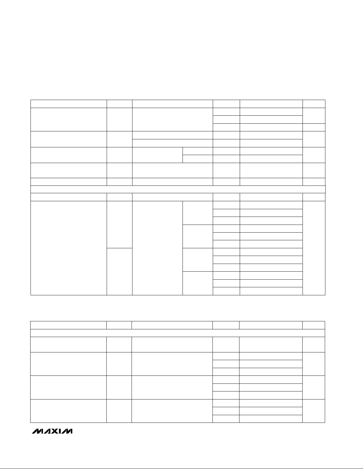
OUT2
OUT3V-
1
2
87V+
OUT1IN2
IN3
IN1
SO/DIP
3
4
6
5
MAX4506
TOP VIEW
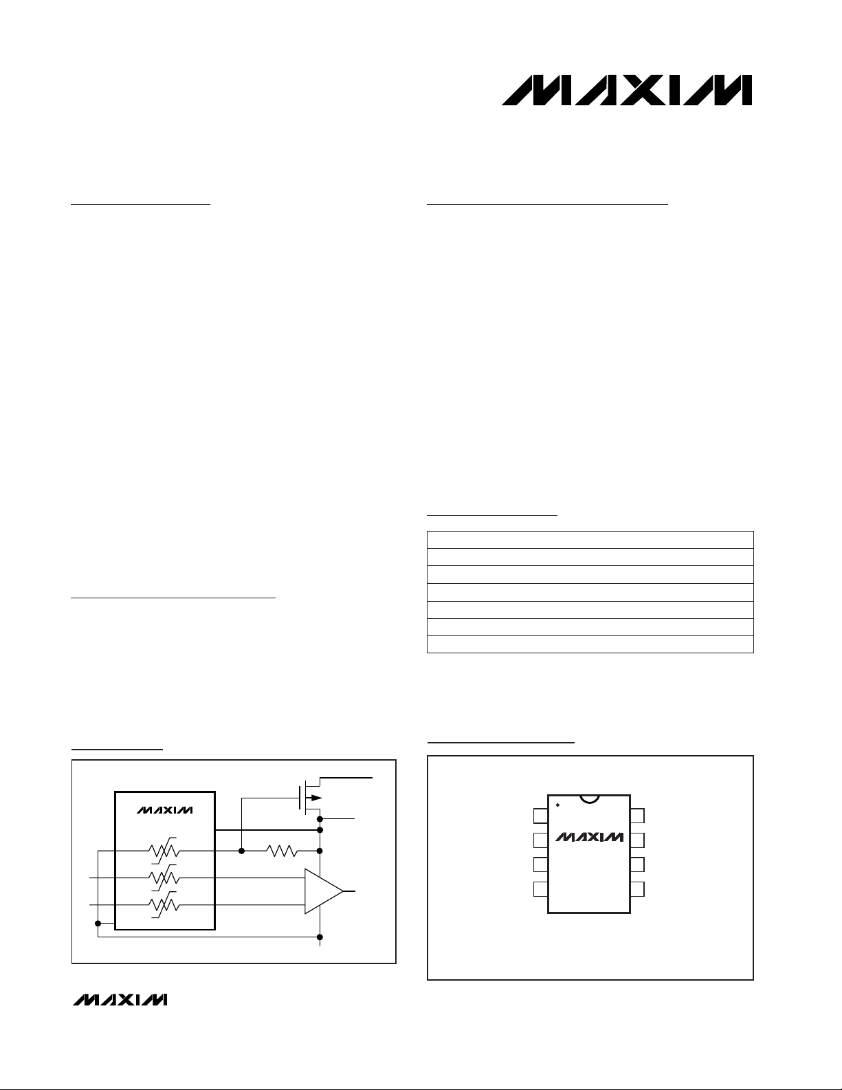
Typical Operating Circuit
19-1415; Rev 1; 8/99
PART
MAX4506ESA
MAX4506EPA
MAX4506MJA -55°C to +125°C
-40°C to +85°C
-40°C to +85°C
TEMP. RANGE PIN-PACKAGE
8 SO
8 Plastic DIP
8 CERDIP**
Ordering Information continued at end of data sheet.
*
Contact factory for dice specifications.
**
Contact factory for availability.
Rail-to-Rail is a registered trademark of Nippon Motorola, Ltd.
Pin Configurations continued at end of data sheet.
Pin Configurations
Ordering Information
MAX4506CPA 0°C to +70°C 8 Plastic DIP
MAX4506C/D 0°C to +70°C Dice*
MAX4506CSA
0°C to +70°C 8 SO
SWITCHED +15V
P
MAX4506
IN1
17
IN2
26
IN3
3
4
V-
OUT1
OUT2
OUT3
V+
8
5
100k
OP AMP
-15V
+15V
Page 2

MAX4506/MAX4507
Fault-Protected, High-Voltage
Signal-Line Protectors
2 _______________________________________________________________________________________
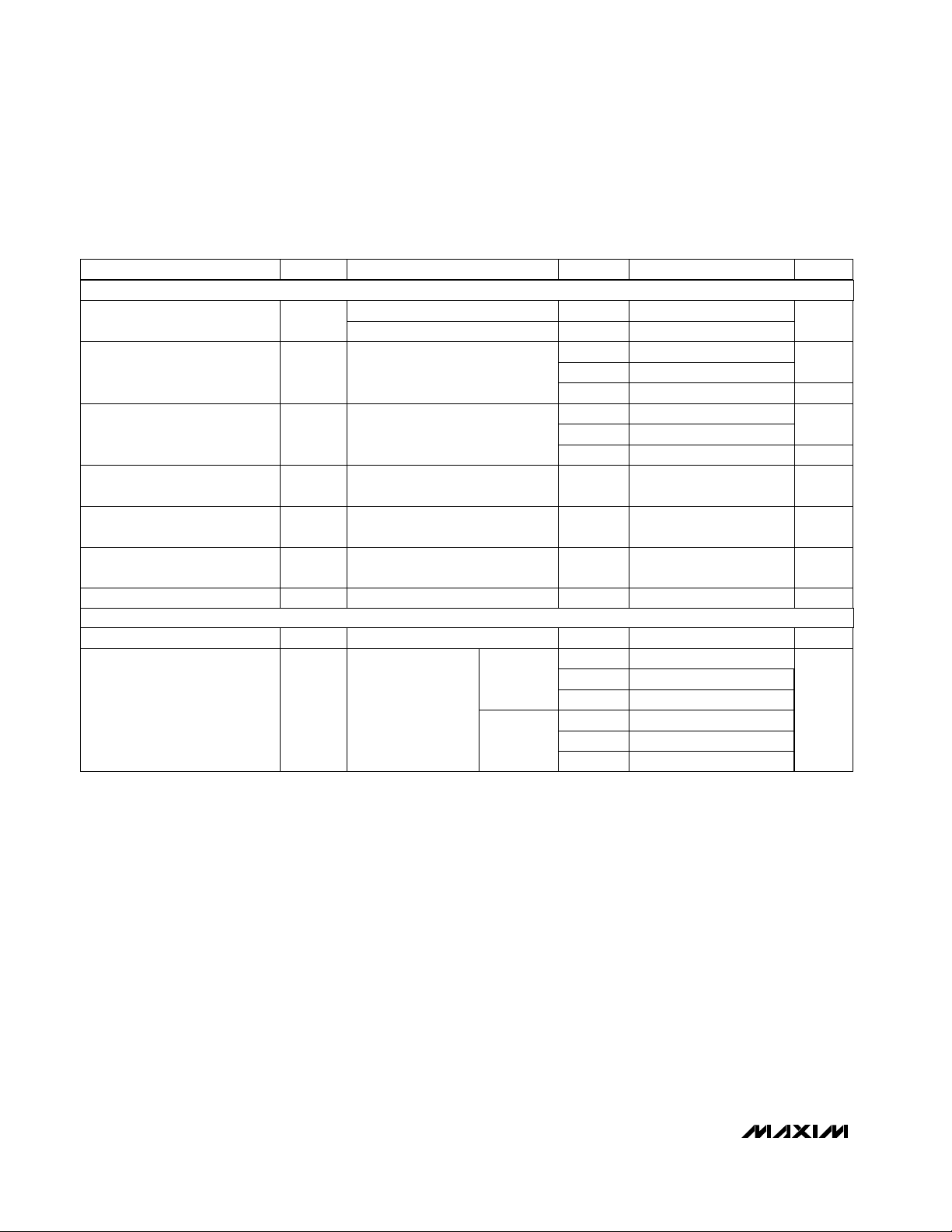
ABSOLUTE MAXIMUM RATINGS
ELECTRICAL CHARACTERISTICS
(V+ = +15V, V- = -15V, TA= T
MIN
to T
MAX
, unless otherwise noted. Typical values are at TA= +25°C.) (Note 3)
Stresses beyond those listed under “Absolute Maximum Ratings” may cause permanent damage to the device. These are stress ratings only, and functional
operation of the device at these or any other conditions beyond those indicated in the operational sections of the specifications is not implied. Exposure to
absolute maximum rating conditions for extended periods may affect device reliability.
(Voltages Referenced to GND)
V+........................................................................-0.3V to +44.0V
V- .........................................................................-44.0V to +0.3V
V+ to V-................................................................-0.3V to +44.0V
IN_ or OUT_ .........................................................................±44V
IN_ Overvoltage with Power On...........................................±36V
IN_ Overvoltage with Power Off...........................................±40V
Continuous Current into Any Terminal..............................±30mA
Peak Current into Any Terminal
(pulsed at 1ms, 10% duty cycle).................................±70mA
Continuous Power Dissipation (T
A
= +70°C)
8-Pin Narrow SO (derate 5.88mW/°C above +70°C) ....471mW
8-Pin Plastic DIP (derate 9.09mW/°C above +70°C) .....727mW
8-Pin CERDIP (derate 8.00mW/°C above +70°C) ...........640mW
18-Pin Wide SO (derate 9.52mW/ °C above +70°C) .......762mW
18-Pin Plastic DIP (derate 11.11mW/ °C above +70°C) ...889mW
18-Pin CERDIP (derate 10.53mW/ °C above +70°C) ......842mW
20-Pin SSOP (derate 11.11mW/°C above +70°C) ...........640mW
Operating Temperature Ranges
MAX4506C_A /MAX4607C_ _.............................0°C to +70°C
MAX4506E_A/MAX4607E_ _ ...........................-40°C to +85°C
MAX4506MJA/MAX4607MJN ........................-55°C to +125°C
Storage Temperature Range .............................-65°C to +160°C
Lead Temperature (soldering, 10sec) .............................+300°C
RECOMMENDED OPERATING GUIDELINES
V+ to GND..............................................................-0.3V to +40V
V- to GND ...............................................................-32V to +0.3V
V+ to V- ..................................................................................40V
IN_........................................................................................±40V
OUT_ ...............................................................................V+ to V-
IN_ to OUT_..........................................................40V Differential
Continuous Current into Any Terminal ..............................≤30mA
Peak Current into Any Terminal
(pulsed at 1ms, 10% duty cycle) .................................≤70mA
C
IN
Input Capacitance pF20VIN= 0, f = 1MHz +25°C
V
IN_
Fault-Protected Analog Signal
Range
V
-36 36
(Notes
2, 3)
C, E, MApplies with power on
-20 0.1 20
-40 40
nA
C, E, M
-200 200
C, E
+25°C
V
IN_
= ±25V, V
OUT_
= open
Applies with power off
I
IN_
Input Signal-Path Leakage
Current, Supplies On
-10 10
65 100
R
ON
V
V- V+
V
IN_
Fault-Free Analog Signal Range
(Note 4)
-400 400
I
OUT_ON
Signal-Path Leakage Current
(Note 7)
µA
-20 20
nA
-0.5 0.5
12
125
Ω
150
Analog Signal-Path Resistance
Ω
17
∆R
ON
Signal-Path Resistance Match
(Note 6)
10
UNITSMIN TYP MAXSYMBOLPARAMETER
V+ = +15V, V- = -15V,
V
IN_
= ±15V
V
OUT_
= ±10V, V
IN_
= ±10V or
floating
V
IN_
= ±10V, I
OUT_
= 1mA
V
IN_
= V
OUT_
= ±10V, I
OUT
= 1mA
CONDITIONS
+25°C
C, E, M
M
C, E
+25°C
M
C, E
M
+25°C
C, E
M
T
A
ANALOG SWITCH
FAULT PROTECTION
Note 1: OUT_ pins are not fault protected. Signals on OUT_ exceeding V+ or V- are clamped by internal diodes. Limit forward-diode
current to maximum current rating.
Note 2: IN_ pins are fault protected. Signals on IN_ exceeding -36V to +36V may damage the device. These limits apply with power
applied to V+ or V-, or ±40V with V+ = V- = 0.
Page 3
µA
MAX4506/MAX4507
Fault-Protected, High-Voltage
Signal-Line Protectors
_______________________________________________________________________________________ 3
ELECTRICAL CHARACTERISTICS—Single Supply
(V+ = +12V, V- = -0V, TA= T
MIN
to T
MAX
, unless otherwise noted. Typical values are at TA= +25°C.) (Note 3)
ELECTRICAL CHARACTERISTICS —Dual Supplies (continued)
(V+ = +15V, V- = -15V, TA= T
MIN
to T
MAX
, unless otherwise noted. Typical values are at TA = +25°C.) (Note 3)
MAX4506
MAX4507
-20 0.2 20
-400
-300
MAX4506
MAX4507
400
-250 -160
Power-Supply Current
300
-200
160 250
200
175
-175
µA
90 150
-150 -90
I-
I+
V
IN_
= +15V
M
C, E
+25°C
M
C, E
+25°C
nA
-500 500
C, E
+25°C
V
IN_
= ±40V, V
OUT_
= open,
V+ = 0, V- = 0
I
IN_
Input Signal-Path Leakage
Current, Supplies Off
-10 10
M µA
13 19 26
mA
-26 -19 -13
+25°C
+25°CV
IN_
= +25V
I
OUT_
Output Clamp Current,
Supplies On
0.5 1.0
kΩ
0.4 1.0
+25°C
+25°C
UNITSMIN TYP MAXSYMBOLPARAMETER
I
OUT
= 1mAR
OUT_
Output Clamp Resistance,
Supplies On
V
IN_
= -25V
V
IN_
= +25V
V
IN_
= -25V
±8 ±18
C, E, M
+25°C ns
± Fault Output Turn-On Delay
Time (Note 5)
RL= 10kΩ, V
IN_
= ±25V
Power-Supply Range
CONDITIONS
V+, V-
M
C, E
+25°C
M
C, E
+25°C
T
A
2.5
V
10
µs+25°C± Fault Recovery Time (Note 5) RL= 10kΩ, V
IN_
= ±25V
125 200
R
ON
V
0V+
V
IN_
Fault-Free Analog Signal Range
(Note 4)
20
∆R
ON
Signal-Path Resistance Match
(Note 6)
15
Ω
312
250
Ω
300
Analog Signal-Path Resistance
UNITSMIN TYP MAXSYMBOLPARAMETER
V+ = +12V, V- = 0
V
IN_
= +12V
V
IN_
= +10V, I
OUT_
= 1mA
V
IN_
= +10V, I
OUT_
= 1mA
CONDITIONS
+25°C
C, E, M
M
C, E
+25°C
C, E
M
T
A
POWER SUPPLY
-400 400
I
OUT_(ON)
Signal-Path Leakage Current
(Note 7)
-20 20
nA
-0.5 0.05 0.5
V
IN
= +10V or floating
M
C, E
+25°C
ANALOG SWITCH
Page 4
MAX4506/MAX4507
Fault-Protected, High-Voltage
Signal-Line Protectors
4 _______________________________________________________________________________________
ELECTRICAL CHARACTERISTICS—Single Supply (continued)
(V+ = +12V, V- = -0V, TA= T
MIN
to T
MAX
, unless otherwise noted. Typical values are at TA= +25°C.) (Note 3)
RL= 10kΩ, V
IN_
= +25V± Fault Recovery Time (Note 5) +25°C µs
10
V
2.5
T
A
M
V+
CONDITIONS
Power-Supply Range
RL= 10kΩ, V
IN_
= +25V
± Fault Output Turn-On Delay
Time (Note 5)
ns+25°C
C, E, M
+9 +36
V
IN_
= 25V
PARAMETER SYMBOL MIN TYP MAX UNITS
Output Clamp Current,
Supply On
I
OUT_
+25°C
3 5.5 10
mA
µA
µA
M
-10 10
Input Signal-Path Leakage
Current, Supply Off (Note 9)
I
IN_
-10 10
V
IN_
= ±40V
+25°C
Input Signal-Path Leakage
Current, Supply On (Note 9)
I
IN_
C, E
-500 500
nA
+25°C
C, E
M
+25°C
C, E
M
V
IN_
= +12VI+
925
µA
30
40
17 40
60
Power-Supply Current
80
MAX4507
MAX4506
Applies with power off
V
IN_
= ±25V, V
OUT_
= 0
+25°C
C, E
-200 200
C, E, M
nA
-40 40
-20 0.2 20
-20 0.2 20
Applies with power on C, E, M
-36 36
V
Fault-Protected Analog Signal
Range (Notes 4, 5, 9)
V
IN_
V
IN_
= ±25V
Output Clamp Resistance,
Supply On
R
OUT_
+25°C
1.0 2.5
kΩ
Note 3: The algebraic convention is used in this data sheet; the most negative value is shown in the minimum column.
Note 4: See Fault-Free Analog Signal Range vs. Supply Voltages graph in the
Typical Operating Characteristics
.
Note 5: Guaranteed by design.
Note 6: ∆R
ON
= R
ON(MAX)
- R
ON(MIN)
Note 7: Leakage parameters are 100% tested at maximum rated hot temperature and guaranteed by correlation at TA= +25°C.
Note 8: Leakage testing for single-supply operation is guaranteed by testing with dual supplies.
Note 9: Guaranteed by testing with dual supplies.
POWER SUPPLY
FAULT PROTECTION
Page 5

MAX4506/MAX4507
Fault-Protected, High-Voltage
Signal-Line Protectors
_______________________________________________________________________________________
5
0
20
60
40
100
120
80
140
-20 -10 -5-15 0 5 10 15 20
ON-RESISTANCE vs. OUTPUT VOLTAGE
(DUAL SUPPLIES)
MAX4506/07 toc01
V
OUT_
(V)
R
ON
(Ω)
V+ = +18V
V- = -18V
V+ = +15V
V- = -15V
V+ = +10V
V- = -10V
V+ = +8V
V- = -8V
0
50
150
100
200
250
010155 20253035
ON-RESISTANCE vs. OUTPUT VOLTAGE
(SINGLE SUPPLY)
MAX4506/07 toc02
V
OUT_
(V)
R
ON
(Ω)
V+ = +12V
V+ = +9V
V+ = +20V
V+ = +30V
V+ = +36V
V- = 0V
20
0
40
80
60
100
120
-15 -5 0-10 5 10 15
ON-RESISTANCE vs. OUTPUT VOLTAGE
AND TEMPERATURE (DUAL SUPPLIES)
MAX4506/07 toc03
V
OUT_
(V)
R
ON
(Ω)
V+ = +15V
V- = -15V
TA = +125°C
TA = +85°C
TA = +70°C
TA = +25°C
TA = -40°C
TA = -55°C
0
50
150
100
200
250
0462 8 10 12
ON-RESISTANCE vs. OUTPUT VOLTAGE
AND TEMPERATURE (SINGLE SUPPLY)
MAX4506/07 toc04
V
OUT_
(V)
R
ON
(Ω)
TA = +125°C
TA = +85°C
TA = +70°C
TA = +25°C
TA = -40°C
TA = -55°C
V+ = +12V
V- = 0
-20
-15
-10
-5
0
5
10
15
20
-30 -10-20 0 102030
OUTPUT TRANSFER CHARACTERISTICS
(DUAL SUPPLIES)
MAX4506/07 toc07
INPUT VOLTAGE (V)
OUTPUT CLAMP VOLTAGE (V)
(V+ = +18V, V- = -18V)
(V+ = +15V, V- = -15V)
(V+ = +10V, V- = -10V)
(V+ = +8V, V- = -8V)
(V+ = +8V, V- = -8V)
(V+ = +10V, V- = -10V)
(V+ = +15V, V- = -15V)
(V+ = +18V, V- = -18V)
OUTPUT LOAD = 1MΩ
INPUT VOLTAGE
LINEARLY SWEPT
BETWEEN -30V
AND +30V
0
0.2
0.1
0.5
0.4
0.3
0.7
0.6
0.8
-55 -5 25-35 -15 45 65 85 105 125
OUTPUT CLAMP RESISTANCE SUPPLIES ON
MAX4506/07 toc05
TEMPERATURE (°C)
R
OUT
(kΩ)
V+ = +15V
V- = -15V
V
IN
= ±25V
VIN = +25V
VIN = -25V
-25
-15
-20
0
-5
-10
5
10
20
15
25
-55 -25 -10-40 5 20 35 50 65 80 95 110 125
OUTPUT CLAMP CURRENT SUPPLIES ON
vs. TEMPERATURE
MAX4506/07 toc06
TEMPERATURE (°C)
I
OUT
(mA)
V+ = +15V
V- = -15V
0
5
10
15
20
25
30
35
40
0105 152025303540
OUTPUT TRANSFER CHARACTERISTICS
(SINGLE SUPPLY)
MAX4506/07 toc08
INPUT VOLTAGE (V)
OUTPUT CLAMP VOLTAGE (V)
INPUT VOLTAGE LINEARLY SWEPT
BETWEEN 0 AND 35V
OUTPUT LOAD = 1MΩ
V- = 0
V+ = +9V
V+ = +25V
V+ = +36V
V+ = +15V
V+ = +12V
-20
-15
-10
-5
0
5
10
15
20
-20 -10-15 -5 0 5 10 15 20
FAULT-FREE ANALOG SIGNAL RANGE
vs. SUPPLY VOLTAGE
MAX4506/07 toc09
INPUT VOLTAGE (V)
OUTPUT VOLTAGE (V)
Typical Operating Characteristics
(TA = +25°C, unless otherwise noted.)
Page 6

MAX4506/MAX4507
Fault-Protected, High-Voltage
Signal-Line Protectors
6 _______________________________________________________________________________________
Typical Operating Characteristics (continued)
(TA= +25°C, unless otherwise noted.)
0.01p
0.1p
10p
1p
1n
10n
100p
100n
-55 -5 20-30 45 70 95 120 145
FAULT-FREE OUTPUT LEAKAGE CURRENT
WITH SUPPLIES ON
MAX45506/07 toc10
TEMPERATURE (°C)
LEAKAGE CURRENT (A)
V
OUT
= ±10υ
I
OUT
(V+ = +15V, V- = -15V)
I
OUT
(V+ = +12V, V- = 0)
0.1p
1p
100p
10p
10n
100n
1n
1µ
-55 -15 5-35 25 45 65 85 105 125
INPUT FAULT LEAKAGE CURRENT
WITH SUPPLIES ON
MAX45506/07 toc11
TEMPERATURE (°C)
LEAKAGE CURRENT (A)
I
IN
AT +25V (V+ = +12V, V - = 0)
I
IN
AT +25V (V+ = +15V, V- = -15V)
50
-50
0
25
-25
125
-125
100
-100
75
-75
150
-150
-55 -15 5-35 25 45 65 85 105 125
MAX4506
POWER-SUPPLY CURRENT
vs. TEMPERATURE
MAX45506/07 toc12
TEMPERATURE (°C)
SUPPLY CURRENT (µA)
V+ = +15V
V- = -15V
I+
I-
I+ SINGLE SUPPLY +12V
50
-50
0
100
-100
150
-150
-200
200
-250
250
-55 -15 5-35 25 45 65 85 105 125
MAX4507
POWER-SUPPLY CURRENT vs.
TEMPERATURE
MAX45506/07 toc13
TEMPERATURE (°C)
SUPPLY CURRENT (µA)
V+ = +15V
V- = -15V
I+
I-
I+ SINGLE SUPPLY + 12V
20
-20
0
40
-40
60
-60
-80
80
-100
100
-15 5 010 5 10 15
SUPPLY CURRENT vs.
INPUT VOLTAGE
MAX45506/07 toc14
INPUT VOLTAGE (V)
SUPPLY CURRENT (µA)
I+
I-
10
-100
0.01 1 100.1 1000100
FREQUENCY RESPONSE
-90
MAX4506/07 toc15
FREQUENCY (MHz)
RESPONSE (dB)
-80
-70
-60
-50
-40
-30
-20
-10
0
V+ = +15V
V- = -15V
CROSSTALK
BANDWIDTH
IN_
10V/div
+15V
-15V
+15V
0V
-15V
10V/div
OUT_
5µs/div
FAULT-FREE SIGNAL PERFORMANCE
MAX45506/07 toc16
FAULT-FREE RAIL-TO-RAIL SIGNAL HANDLING
WITH ±15V SUPPLIES
IN_
+25V
0V
+15V
0V
-25V
-15V
±25V OVERVOLTAGE INPUT WITH THE OUTPUT
CLAMPED AT ±15V
0V
OUT_
5µs/div
INPUT OVERVOLTAGE
vs. OUTPUT CLAMPING
MAX45506/07 toc17
IN_
5V/div
0V
+16V
+15V
0V
OUT_
5V/div
5µs/div
FAULT RECOVERY
MAX45506/07 toc18
V+ = +15V
V- = -15V
Page 7

MAX4506/MAX4507
Fault-Protected, High-Voltage
Signal-Line Protectors
_______________________________________________________________________________________ 7
8-Pin
DIP/SO
18-Pin
DIP/SO
NAME*
1, 2, 3 1, 2, 3 IN1, IN2, IN3
PIN
– 4–8 IN4, IN5, IN6, IN7, IN8
4 9 V-
– – N.C.
8 18 V+
5, 6, 7 15, 16, 17 OUT3, OUT2, OUT1
– 10–14 OUT8, OUT7, OUT6, OUT5, OUT4
Pin Description
FUNCTION
Signal Inputs 1, 2, 3
Signal Inputs 4, 5, 6, 7, 8
Negative Supply Voltage Input
No Connection. Not internally connected.
Positive Supply-Voltage Input
Signal Outputs 3, 2, 1
Signal Outputs 8, 7, 6, 5, 4
20-Pin
SSOP
1, 2, 4
5–9
10
3, 18
20
16, 17, 19
11–15
MAX4506 MAX4507
*
Connect all unused inputs to a hard voltage within the supply range (e.g., V+, V-, or GND).
Detailed Description
The MAX4506/MAX4507 protect other ICs from overvoltage by clamping its output voltage to the supply
rails. If the power supplies to the device are off, the
device clamps the output to 0V. The MAX4506/
MAX4507 provide protection for input signals up to
±36V with the power supplies on and ±40V with the
power supplies off.
The MAX4506/MAX4507 protect other integrated circuits connected to its output from latching up. Latchup
is caused by parasitic SCR(s) within the IC turning on,
and can occur when the supply voltage applied to the
IC exceeds the specified operating range. Latchup can
also occur when signal voltage is applied before the
power-supply voltage. When in a latchup state, the circuit draws excessive current and may continue to draw
excessive current even after the overvoltage condition
is removed. A continuous latchup condition may damage the device permanently. Such “faults” are commonly encountered in modular control systems where
power supplies to interconnected modules may be
interrupted and reestablished at random. Faults can
happen during production testing, maintenance, startup, or a power failure.
Figure 1 shows the normal complementary pair (N1 and
P1) found in many common analog switches. In addition to these transistors, the MAX4506/MAX4507 also
contain comparators and sensing and clamping circuitry
to control the state of N1 and P1. During normal opera-
tion, N1 and P1 remain on with a typical 65Ω on-resis-
tance between IN and OUT.
The on-board comparators and sensing circuitry monitor the input voltage for possible overvoltage faults.
-15V
-15V
+15V
P-CHANNEL
DRIVER
N-CHANNEL
DRIVER
+15V
N3
P3
IN
N1
CLAMP
OUT
CLAMP
+V(+15V)
-V(-15V)
N2
P2
P1
COMPARATOR
COMPARATOR
SENSE
SWITCH
SENSE
SWITCH
Figure 1. Simplified Internal Structure
Page 8

MAX4506/MAX4507
Fault-Protected, High-Voltage
Signal-Line Protectors
8 _______________________________________________________________________________________
Two clamp circuits limit the output voltage to within the
supply voltages. When the power supplies are off, any
input voltage applied at IN turns off both N1 and P1,
and OUT is clamped to 0V.
Normal Operation
When power is applied, each protector acts as a resistor in series with the signal path. Any voltage source on
the “input” side of the switch will be conducted through
the protector to the output (Figure 2).
When the output load is resistive, it draws current
through the protector. The internal resistance is typically
less than 100Ω. High-impedance loads are relatively
unaffected by the presence of the MAX4506/MAX4507.
The protector’s path resistance is a function of the supply
voltage and the signal voltage (see
Typical Operating
Characteristics
).
Fault Protection, Power Off
When power is off (i.e., V+ = V- = 0), the protector is a
virtual open circuit. With up to ±40V applied to the input
pin, the output pin will be 0V.
Fault Protection, Power On
A fault condition exists when the voltage on the IN_
exceeds either supply rail. This definition is valid when
power is on or off, as well as during all states while
power ramps up or down.
Applications Information
Supplying Power Through External ICs
The MAX4506/MAX4507 have low supply currents
(<250µA), which allows the supply pins to be driven by
other active circuitry instead of connected directly to
the power sources. In this configuration, the parts can
be used as driven fault-protected switches with V+ or
V- used as the control pins. For example, with the Vpin grounded, the output of a CMOS gate can drive the
V+ pin to turn the device on and off. This can effectively
connect and disconnect three (MAX4506) or eight
(MAX4507) separate signal lines at once. Ensure that
the driving source(s) does not drive the V+ pin more
negative than the V- pin.
Figure 3 shows a simple turn-on delay that takes
advantage of the MAX4506’s low power consumption.
The two RC networks cause gradual application of
power to the MAX4506, which in turn applies the input
signals smoothly after the amplifier has stabilized. The
two diodes discharge the two capacitors rapidly when
the power turns off. Note that the IC used to supply
power to the MAX4506/MAX4507 must be able to supply enough current to maintain the load voltage at the
supply rail in a fault condition.
MAX4506
R
OUT
V
IN
IN1
V- V- V+V+
1
4
7
8
OUT1
Figure 2. Application Circuit
MAX4506
IN3
V-
-15V
V+
+15V
3
4
5
10µF
10µF
OUT3
IN2
26
OUT2
IN1
17
OUT1
8
100k
100k
OP AMP
Figure 3. Turn-On Delay
Page 9

MAX4506/MAX4507
Fault-Protected, High-Voltage
Signal-Line Protectors
_______________________________________________________________________________________ 9
Protectors as Circuit Elements
Each of the protectors in a MAX4506/MAX4507 may be
used as a switched resistor, independent of the functions of other elements in the same package. For example, Figure 4 shows a MAX4506 with two of the
protectors used to protect the input of an op amp, and
the third element used to sequence a power supply.
Combining the circuits of Figures 3 and 4 produces a
delayed action on the switched +15V, as well as
smooth application of signals to the amplifier input.
Figure 5 shows MAX4506 used in front of a MAX338
unprotected 1-to-8 multiplexer. With supplies at ±15V,
V
OUT
of the MAX4506 clamps to ±15V; V
OUT
of the
MAX338 goes to ±14V. With supplies off, V
OUT
goes to
0V while the inputs remain at ±25V.
Use the MAX4506 with a MAX338 to enhance voltage
handling capability (Figure 6). The MAX4506 and
MAX338 share almost equal voltage drops in this configuration. For example, applying ±40V on pins 1 and 2
of the MAX4506 causes a voltage drop of about 26V
across pin 1 of the MAX4506 to pin 4 of the MAX338,
and a voltage drop of about 28V across pin 4 of the
MAX4506 to pin 8 of the MAX338. Similarly, there is a
26V drop from pin 2 of the MAX4506 to pin 5 of the
MAX338. The system’s performance exceeds each
individual part’s specification because of shared voltage drops.
Multiplexer and Demultiplexer
As shown in Figure 7, the MAX4506 can be used in
series with the output of a MAX4508 (1-to-8 multiplexer)
to act as multiplexer or demultiplexer. The MAX4508 is a
fault-protected multiplexer whose inputs are designed to
interface with harsh environments; however, its common
output is not fault protected if connected to outside signals (i.e., demultiplexer use). If the common output can
see fault signals, then it needs to be protected, and the
MAX4506 can be added to provide complete protection.
SWITCHED +15V
MAX4506
IN3
V-
-15V
V+
+15V
3
4
5
OUT3
IN2
26
OUT2
IN1
17
OUT1
8
P
100k
OP AMP
Figure 4. Power-Supply Sequencing
16
15
14
13
12
11
10
9
1
2
3
4
5
6
7
8
MAX4508
-15V
1
2
87+15V
NEW COM
3
4
6
5
MAX4506
A1
A2
GND
V+
NO5
NO6
NO7
NO9
A
O
EN
V-
O
+5V
+3V
+15V
-15V
NO3
NO1
NO2
NO4
COM
Figure 7. Multiplexer and Demultiplexer Application Using
MAX4506 (or MAX4507) with MAX4508
V
OUT
= -14V
+40V
-40V
10k
6
471
52
8
MAX338
MAX4506
Figure 6. SPDT Switch Application
Figure 5. Protecting a MAX338 with a MAX4506
+3V
OV
+25V
-25V
1
2
87+15V
MAX4506
3
-15V
4
6
5
+5V
-5V
R
L
1
A
O
2
EN
V-
3
4
NO1
NO2
5
NO3
6
NO4
7
V
8
OUT
MAX338
GND
NO5
NO6
NO7
NO9
16
A1
15
A2
14
+15V
V+
13
12
11
10
9
Page 10

MAX4506/MAX4507
As seen in Figure 7, the signal input can now be put
into pin 1 of the MAX4506 (new common output for system), and outputs can be taken at MAX4508 pins 4 to
7, and 9 to 12. This is the classic demultiplexer operation. This system now has full protection on both of the
multiplexers’ inputs and outputs.
Measuring Path Resistance
Measuring path resistance requires special techniques,
since path resistance varies dramatically with the IN
and OUT voltages relative to the supply voltages.
Conventional ohmmeters should not be used for the following two reasons: 1) the applied voltage and currents
are usually not predictable, and 2) the true resistance is
a function of the applied voltage, which is dramatically
altered by the ohmmeter itself. Autoranging ohmmeters
are particularly unreliable.
Figure 8 shows a circuit that can give reliable results.
This circuit uses a 100mV voltage source, a low-voltage-drop ammeter as the measuring circuit, and an
adjustable supply to sweep the analog voltage across
its entire range. The ammeter must have a voltage drop
of less than one millivolt (up to the maximum test current) for accurate results. A Keithley model 617 electrometer has a suitable ammeter circuit, appropriate
ranges, and a built-in voltage source designed for this
type of measurement. Find the path resistance by setting the analog voltage, measuring the current, and calculating the path resistance. Repeat the procedure at
each analog and supply voltage.
Note: It is important to use a voltage source of 100mV
or less. As shown in Figure 8, this voltage and the V
IN
voltage form the V
OUT
voltage. Using higher voltages
could cause OUT to go into a fault condition prematurely.
High-Voltage Surge Suppression
These devices are not high-voltage arresters, nor are
they substitutes for surge suppressors. However, the
MAX4506/MAX4507 can fill a vital gap in systems that
use these forms of protection (Figure 9). Although surge
suppressors are extremely fast shunt elements, they
have very soft current knees. Their clamp voltage must
be chosen well above the normal signal levels, because
they have excessive leakage currents as the analog
signal approaches the knee. This leakage current can
interfere with normal operation when signal levels are
low or impedance is high. If the clamp voltage is too
high, the input can be damaged.
Connecting a MAX4506/MAX4507 after a surge suppressor allows the surge-suppressor voltage to be set
above the supply voltage (but within the overvoltage
limits), dramatically reducing leakage effects (Figure 9).
During a surge, the surge suppressor clamps the input
voltage roughly to the ±10V supplies.
Fault-Protected, High-Voltage
Signal-Line Protectors
10 ______________________________________________________________________________________
MAX4506
V
OUT
V
IN
IN1
V- V+V+
100mV
PATH RESISTANCE = 100mv/A
ADJUSTABLE
ANALOG
VOLTAGE
84
OUT1
A
Figure 8. Path-Resistance Measuring Circuit
Figure 9. Surge-Suppression Circuit
IN1
17
IN2
26
IN3
3
4
V-
SURGE SUPPRESSORS
-15V
MAX4506
OUT1
OUT2
OUT3
+10V
8
V+
OP AMP
5
-10V
Page 11

MAX4506/MAX4507
Fault-Protected, High-Voltage
Signal-Line Protectors
______________________________________________________________________________________ 11
Ordering Information (continued)
Chip Topographies
20 SSOP
MAX4507CAP
18 Plastic DIPMAX4507CPN
18 SOMAX4507CWN
18 SO
20 SSOP
Dice*
MAX4507EWN
MAX4507EAP
MAX4507C/D
18 Plastic DIPMAX4507EPN
18 CERDIP**MAX4507MJN
*
Contact factory for dice specifications.
**
Contact factory for availability.
PART PIN-PACKAGETEMP. RANGE
0°C to +70°C
0°C to +70°C
0°C to +70°C
-40°C to +85°C
-40°C to +85°C
0°C to +70°C
-40°C to +85°C
-55°C to +125°C
OUT1
OUT2
OUT3
0.112"
(2.84mm)
0.071"
(1.80mm)
V+
IN1
IN2
IN3
V-
0.112"
(2.84mm)
0.071"
(1.800mm)
V-
OUT8
OUT7
OUT6
OUT5
OUT4
OUT3
OUT2
IN1 V+
OUT1
IN2
IN3
IN4
IN5
IN6
IN7
IN8
MAX4506
MAX4507
TRANSISTOR COUNT:
144 (MAX4506)
379 (MAX4507)
SUBSTRATE CONNECTED TO V+
Page 12

MAX4506/MAX4507
Fault-Protected, High-Voltage
Signal-Line Protectors
Maxim cannot assume responsibility for use of any circuitry other than circuitry entirely embodied in a Maxim product. No circuit patent licenses are
implied. Maxim reserves the right to change the circuitry and specifications without notice at any time.
12
____________________Maxim Integrated Products, 120 San Gabriel Drive, Sunnyvale, CA 94086 408-737-7600
© 1999 Maxim Integrated Products Printed USA is a registered trademark of Maxim Integrated Products.
Package Information
SSOP.EPS
Pin Configurations (continued)
18
17
16
15
14
13
12
11
1
2
3
4
5
6
7
8
V+
OUT1
OUT2
OUT3IN4
IN3
IN2
IN1
OUT4
OUT5
OUT6
OUT7IN8
IN7
IN6
IN5
109 OUT8V-
SO/DIP
MAX4507
20
19
18
17
16
15
14
13
1
2
3
4
5
6
7
8
V+
OUT1
N.C.
OUT2IN3
N.C.
IN2
IN1
OUT3
OUT4
OUT5
OUT6IN7
IN6
IN5
IN4
12
11
9
10
OUT7
OUT8V-
IN8
MAX4507
SSOP
TOP VIEW
 Loading...