

Page 1
For free samples & the latest literature: http://www.maxim-ic.com, or phone 1-800-998-8800.
For small orders, phone 1-800-835-8769.
General Description
The MAX4447/MAX4448/MAX4449 single-ended-todifferential line drivers are designed for high-speed
communications. Using current feedback for greater
bandwidth, these devices deliver full-power bandwidths
up to 405MHz and feature slew rates as high as
6500V/µs. The MAX4447 has a fixed gain of +2V/V and
a small-signal bandwidth of 430MHz. The MAX4448/
MAX4449 have small-signal bandwidths of 330MHz
and 400MHz, respectively, and are internally compensated for minimum gain configurations of +2V/V and
+5V/V, respectively. For greater design flexibility, the
MAX4448/MAX4449 allow for variable gain selection
using external gain-setting resistors. A low-power
enable mode reduces current consumption below 5.5mA
and places the outputs in a high-impedance state.
The MAX4447/MAX4448/MAX4449 can deliver differential output swings of ±6.2V from ±5V supplies with a
50Ω load. Excellent differential gain/phase and noise
specifications make these amplifiers ideal for a wide
variety of video and RF signal-processing and transmission applications.
Applications
Differential Line Driver
Single-Ended-to-Differential Conversion
High-Speed Differential Transmitter
Coaxial to Twisted-Pair Converter
Differential Pulse Amplifier
Differential ADC Driver
xDSL Applications
Video and RF Signal Processing and Transmission
Features
♦ 6500V/µs Slew Rate (MAX4449)
♦ Small-Signal Bandwidth
430MHz (MAX4447)
330MHz (MAX4448)
400MHz (MAX4449)
♦ 200MHz 0.1dB Gain Flatness (MAX4447)
♦ 130mA Output Drive Current
♦ +2V/V Internally Fixed Gain (MAX4447)
♦ External Gain Selection
≥+2V/V (MAX4448)
≥+5V/V (MAX4449)
♦ -78dB SFDR at 100kHz
♦ Low Differential Gain/Phase: 0.01%/0.02°
♦ Ultra-Low Noise: 23nV/√Hz at f
IN
= 1MHz
♦ 8ns Settling Time to 0.1%
MAX4447/MAX4448/MAX4449
6500V/µs, Wideband, High-Output-Current, Single-
Ended-to-Differential Line Drivers with Enable
________________________________________________________________
Maxim Integrated Products
1
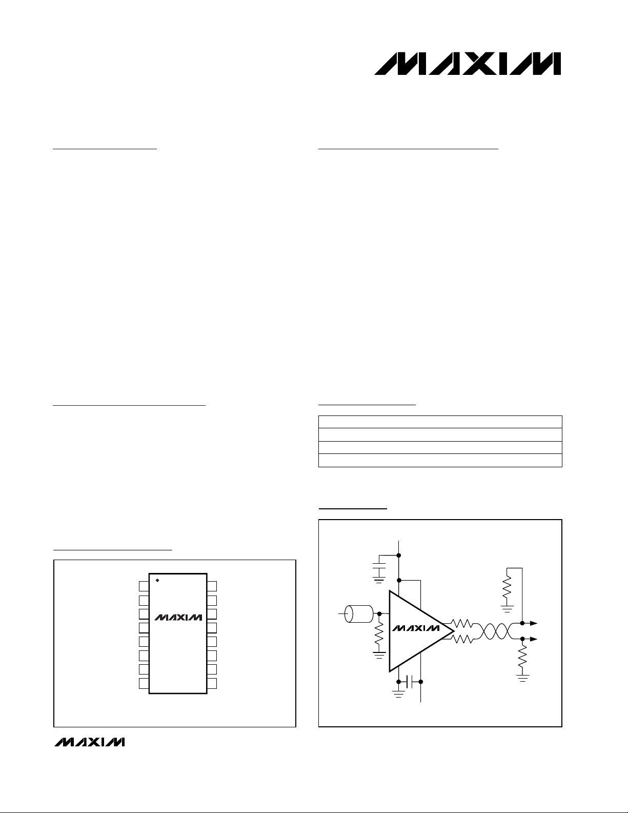
Typical Operating Circuit
19-1519 Rev 0; 8/99
PART
MAX4447ESE
MAX4448ESE
-40°C to +85°C
-40°C to +85°C
TEMP. RANGE PIN-PACKAGE
16 Narrow SO
16 Narrow SO
Pin Configuration
Ordering Information
MAX4449ESE
-40°C to +85°C 16 Narrow SO
+5V
TOP VIEW
1
V
CC
2
V
CC
N.C.
3
MAX4447
4
N.C. (RG)
IN
N.C.
V
EE
V
EE
( ) ARE FOR MAX4448/MAX4449 ONLY
MAX4448
5
MAX4449
6
7
8
SO
16
GND
15
OUT-
14
V
EE
13
V
EE
12
V
EE
V
11
EE
10
OUT+
9
EN
INPUT
75Ω
0.1µF
75Ω
V
CC
IN
MAX4447
GND
0.1µF
75Ω
R
T
OUT+
EN
OUT-
V
EE
-5V
R
T
75Ω
TO
LOAD
Page 2
MAX4447/MAX4448/MAX4449
6500V/µs, Wideband, High-Output-Current, SingleEnded-to-Differential Line Drivers with Enable
2 _______________________________________________________________________________________
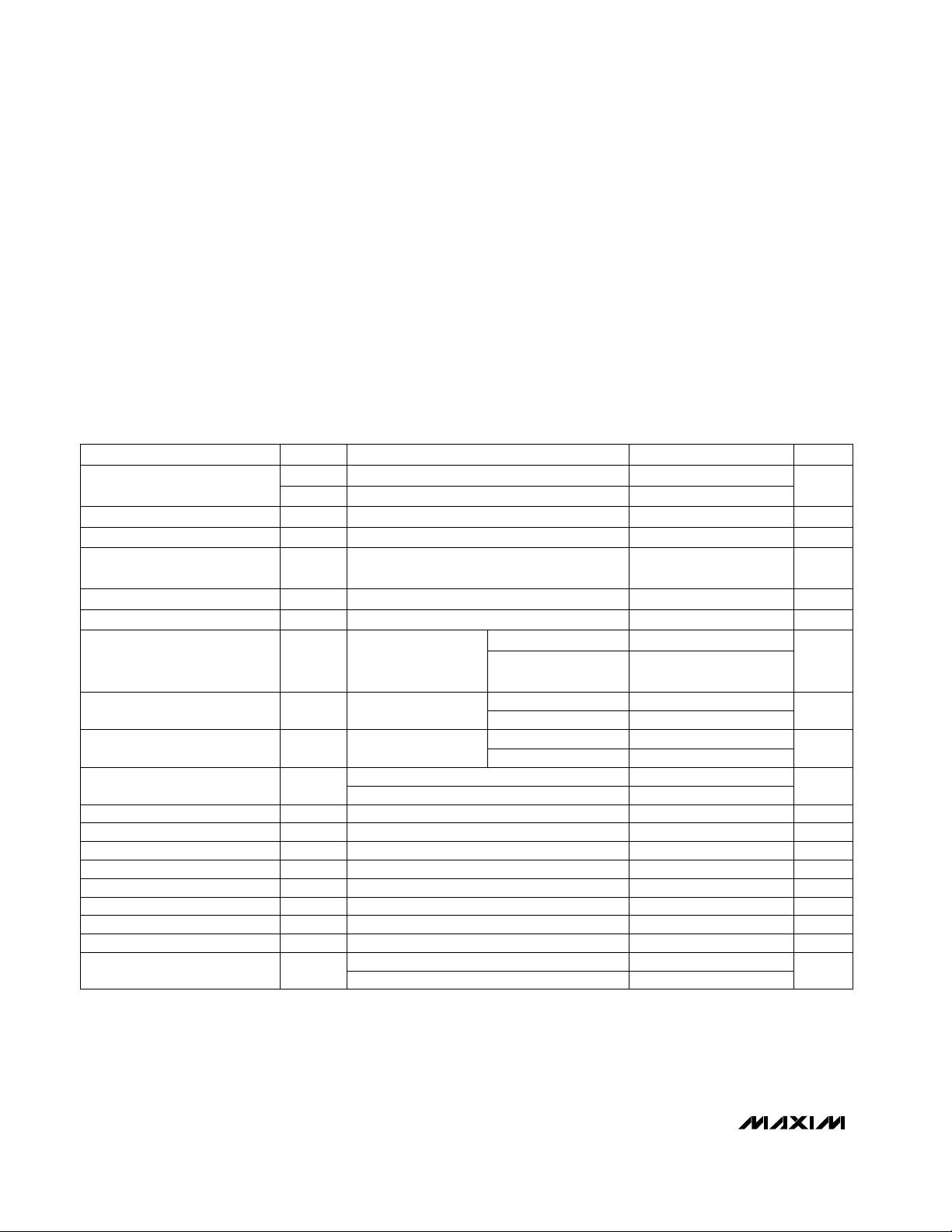
ABSOLUTE MAXIMUM RATINGS
DC ELECTRICAL CHARACTERISTICS
(VCC= +5V, VEE= -5V, VEN≥ 2V, V
OUT
= V
OUT+
- V
OUT-
, RL= ∞, TA= T
MIN
to T
MAX,
unless otherwise noted. Typical values are at
T
A
= +25°C.)
Stresses beyond those listed under “Absolute Maximum Ratings” may cause permanent damage to the device. These are stress ratings only, and functional
operation of the device at these or any other conditions beyond those indicated in the operational sections of the specifications is not implied. Exposure to
absolute maximum rating conditions for extended periods may affect device reliability.
VCCto VEE..........................................................................+12V
Voltage on IN, EN, OUT+, OUT-, RG ....(V
EE
- 0.3V) to (VCC+ 0.3V)
Output Short-Circuit Duration to GND ...........................Indefinite
Continuous Power Dissipation (T
A
= +70°C)
16-Pin Narrow SO (derate 20mW/°C above +70°C) ...1600mW
Operating Temperature Range ...........................-40°C to +85°C
Storage Temperature Range ............................-65°C to +150°C
Lead Temperature (soldering, 10sec) .............................+300°C
VIN= 0, VEN≤ V
IL
VEN= 5V
Guaranteed by gain-error test
VEN= 0
V
EE
guaranteed by PSRR test
V
CC
guaranteed by PSRR test
VEN= 0, V
OUT+
= V
OUT-
= 3.15V or -3.15V
VS= ±4.5V to ±5.5V
Short circuit to GND
RL= 20Ω between OUT+ and OUT-
RL= 50Ω between OUT+ and OUT-
-3.0V ≤ VIN≤ 3.0V
VIN= 0
VIN= 0
RL= 100Ω between OUT+ and OUT-
VIN= 0
CONDITIONS
3.2 5.5
I
Q
Quiescent Current mA
46 55
µA0.8 10I
IH
EN Logic Input High Current
µA-2.5 10I
IL
EN Logic Input Low Current
V2V
IH
EN Logic High Threshold
V0.8V
IL
EN Logic Low Threshold
µA430I
OUT(OFF)
Output Leakage Current
dB53 75PSRRPower-Supply Rejection Ratio
mA140I
SC
Output Short-Circuit Current
mA90 130I
OUT
Output Current Drive
V
±5.2 ±6.2
V
OUT
Output Voltage Swing
±6.3 ±7.4
V-6/A
V
+6/A
V
V
IN
Input Voltage Range
V
-5.5 -4.5V
EE
4.5 5.5V
CC
Operating Supply Voltage
Range
2
kΩ50R
IN
Input Resistance
mV1.3 50V
OS
Input Offset Voltage
µV/°C25TC
VOS
Input Offset Voltage
Temperature Coefficient
µA745I
B
Input Bias Current
UNITSMIN TYP MAXSYMBOLPARAMETER
MAX4447
-6V ≤ V
OUT
≤ 6VA
V
MAX4448/MAX4449
(Note 1)
Gain V/V
2 · (1+300/R
G
)
VIN= 0, VEN≥ V
IH
-6V ≤ V
OUT
≤ 6V %
0.1 2
Gain Error
V
OUT
= 0 %/°C
-0.002
Gain Drift
MAX4447
MAX4447
MAX4448/MAX4449
MAX4448/MAX4449
-0.3 5
0.01
Page 3
Large-Signal -3dB Bandwidth
MAX4447/MAX4448/MAX4449
6500V/µs, Wideband, High-Output-Current, Single-
Ended-to-Differential Line Drivers with Enable
_______________________________________________________________________________________ 3
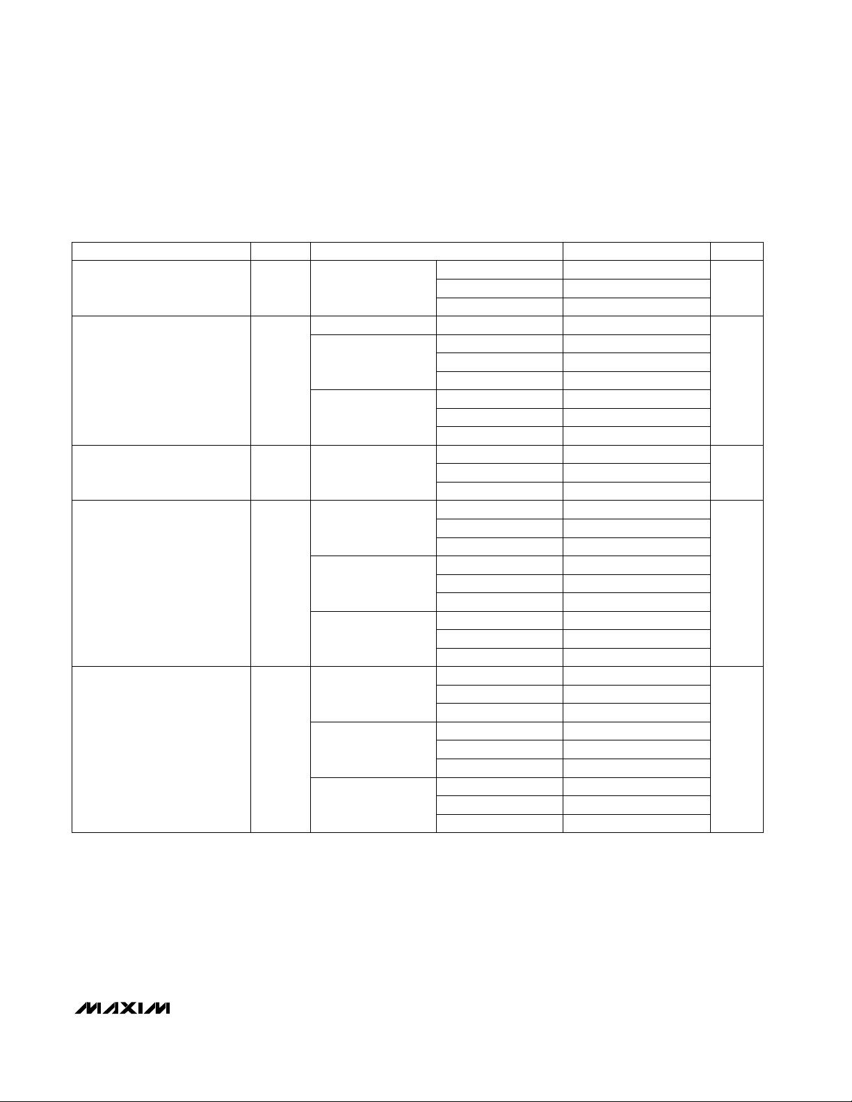
AC ELECTRICAL CHARACTERISTICS
(VCC= +5V, VEE= -5V, RL= 100Ω between OUT+ and OUT-, A
VCL
= +2V/V for MAX4447/MAX4448, A
VCL
= +5V/V for MAX4449,
V
OUT
= V
OUT
+ - V
OUT
-, TA= +25°C, unless otherwise noted.)
V
OUT
= 100mVp-p
CONDITIONS
MHz
400
BW
SS
Small-Signal -3dB Bandwidth
330
430
UNITSMIN TYP MAXSYMBOLPARAMETER
MAX4447
MAX4448
MAX4449
250MAX4449
V
OUT
= 2Vp-p
MHz
405
V
OUT
= 4Vp-p
310
285MAX4447
MAX4448
MAX4449
320
260
250MAX4447
MAX4448
MAX4449
V
OUT
= 8V step
6500
V
OUT
= 100mVp-p
SRSlew Rate (Note 2)
4300
5700MAX4447
MAX4448
MAX4449
V
OUT
= 2V step
V/µs
1800
V
OUT
= 4V step
1900
1700MAX4447
MAX4448
MAX4449
3700
3000
3000MAX4447
MAX4448
MAX4449
MHz
140
0.1dB Gain Flatness
40
200MAX4447
MAX4448
MAX4449
V
OUT
= 8V step
850
t
RISE
Rise Time (Note 2)
1030
670MAX4447
MAX4448
MAX4449
V
OUT
= 2V step
ps
740
V
OUT
= 4V step
520
720MAX4447
MAX4448
MAX4449
660
820
720MAX4447
MAX4448
MAX4449
V
OUT
= 8Vp-p
BW
LS
Large-Signal -3dB Bandwidth
Page 4
MAX4447/MAX4448/MAX4449
6500V/µs, Wideband, High-Output-Current, SingleEnded-to-Differential Line Drivers with Enable
4 _______________________________________________________________________________________
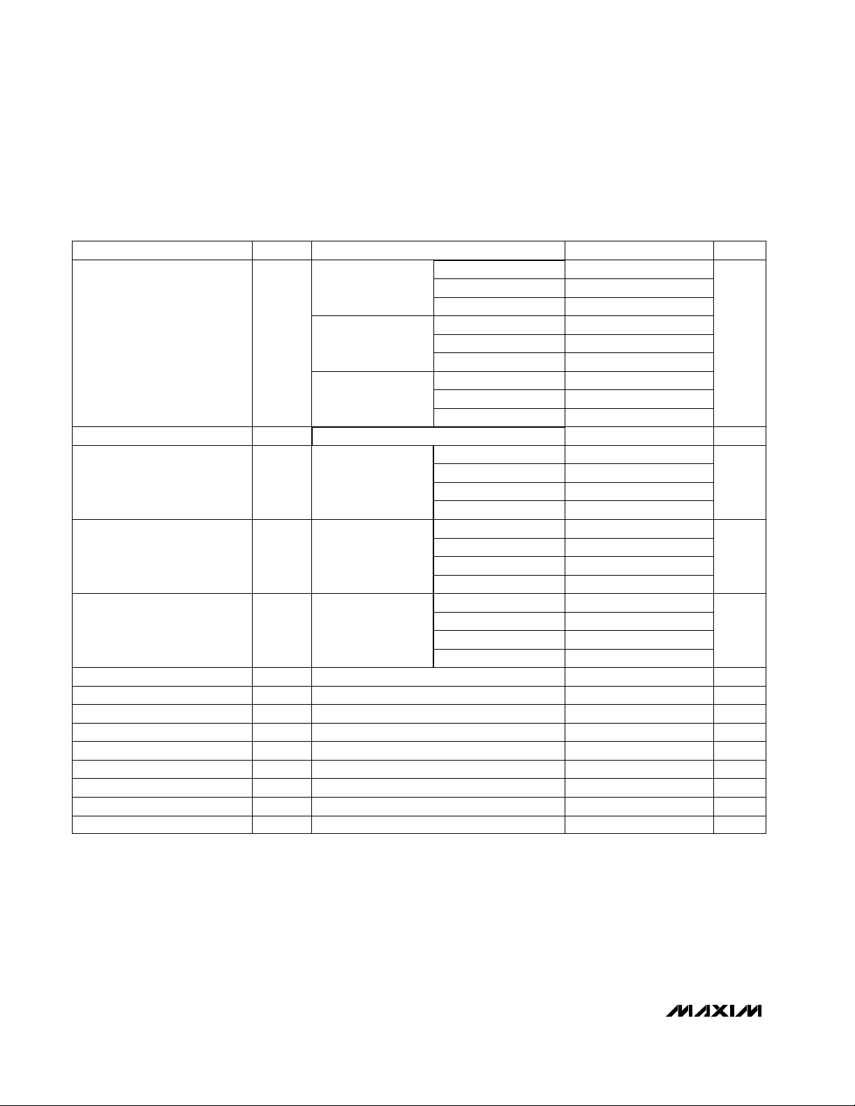
Note 1: RGis the gain resistor. See Figure 1.
Note 2: Input step voltage has <100ps rise (fall) time. Measured at the output from 10% to 90% (90% to 10%) levels.
Note 3: Includes the current noise contribution through the on-die feedback resistor.
AC ELECTRICAL CHARACTERISTICS (continued)
(VCC= +5V, VEE= -5V, RL= 100Ω between OUT+ and OUT-, A
VCL
= +2V/V for MAX4447/MAX4448, A
VCL
= +5V/V for MAX4449,
V
OUT
= V
OUT
+ - V
OUT
-, TA= +25°C, unless otherwise noted.)
µs
nV/√Hz
pA/√Hz
V
OUT
= 4V step
780
V
OUT
= 8V step
810
900MAX4447
MAX4448
MAX4449
V
OUT
= 2V step
660
CONDITIONS
t
FALL
Fall Time (Note 2)
770
800MAX4447
MAX4448
MAX4449
-78
8
fC= 5MHz
ps
900
900
1100
UNITSMIN TYP MAXSYMBOLPARAMETER
MAX4447
MAX4448
MAX4449
dBc
Settling Time
-46
-62fC= 20MHz
fC= 100MHz
NTSC, RL= 150Ω
NTSC, RL= 150Ω
0.01DGDifferential Gain Error
0.02DP
-46
2nd Harmonic Distortion
Differential Phase Error
fC= 100MHz
-62
-78
-78fC= 100kHz
fC= 5MHz
fC= 20MHz
VIN= 1V, V
OUT
settle to within 1%
VIN= 1V, V
OUT
settle to within 1%
VIN= 1V, V
OUT
settle to within 1%
0.08t
ON
Power-Up Time
µs0.4
ns55Enable Time
Disable Time
VIN= 1V, V
OUT
settle to within 1%
f = 10MHz, each output to ground
f = 1MHz
f = 1MHz (Note 3)
Ω1.0Z
OUT±
Output Impedance
%
1.8i
N
24e
N
Input Noise Voltage Density
Input Noise Current Density
µs
0.5t
OFF
Power-Down Time
V
OUT
= 2Vp-p
-54
3rd Harmonic Distortion
fC= 100MHz
-71
-86
-86fC= 100kHz
fC= 5MHz
fC= 20MHz
ns
-78fC= 100kHz
V
OUT
= 2Vp-pSFDRSpurious-Free Dynamic Range dBc
degrees
V
OUT
= 2Vp-p dBc
Page 5

MAX4447/MAX4448/MAX4449
6500V/µs, Wideband, High-Output-Current, Single-
Ended-to-Differential Line Drivers with Enable
_______________________________________________________________________________________
5
Typical Operating Characteristics
(VCC= +5V, VEE= -5V, VEN= +5V, V
OUT
= V
OUT+
- V
OUT-
, RL = 100Ω between OUT+ and OUT-, AV= +2V/V for MAX4447/MAX4448,
AV= +5V/V for MAX4449, TA= +25°C, unless otherwise noted.)
SMALL-SIGNAL GAIN vs. FREQUENCY
4
3
2
1
0
-1
GAIN (dB)
-2
-3
-4
-5
-6
100k 1M 10M 100M 1G
MAX4447
(V
= 100mVp-p)
OUT
FREQUENCY (Hz)
MAX4447 TOC01
SMALL-SIGNAL GAIN vs. FREQUENCY
4
3
2
1
0
-1
GAIN (dB)
-2
-3
-4
-5
-6
100k 1M 10M 100M 1G
MAX4447
GAIN FLATNESS vs. FREQUENCY
(V
= 100mVp-p)
0.5
0.4
0.3
0.2
0.1
0
GAIN (dB)
-0.1
-0.2
-0.3
-0.4
-0.5
100k 1M 10M 100M 1G
OUT
FREQUENCY (Hz)
MAX4447 TOC04
GAIN (dB)
GAIN FLATNESS vs. FREQUENCY
0.5
0.4
0.3
0.2
0.1
0
-0.1
-0.2
-0.3
-0.4
-0.5
100k 1M 10M 100M 1G
MAX4447
LARGE-SIGNAL GAIN vs. FREQUENCY
(V
= 2Vp-p)
4
3
2
1
0
-1
GAIN (dB)
-2
-3
-4
-5
-6
100k 1M 10M 100M 1G
OUT
FREQUENCY (Hz)
MAX4447 TOC07
LARGE-SIGNAL GAIN vs. FREQUENCY
4
3
2
1
0
-1
GAIN (dB)
-2
-3
-4
-5
-6
100k 1M 10M 100M 1G
MAX4448
(V
= 100mVp-p)
OUT
FREQUENCY (Hz)
MAX4448
(V
= 100mVp-p)
OUT
FREQUENCY (Hz)
MAX4448
(V
OUT
FREQUENCY (Hz)
MAX4449
(V
= 100mVp-p)
OUT
FREQUENCY (Hz)
MAX4449
(V
= 100mVp-p)
OUT
FREQUENCY (Hz)
MAX4449
(V
OUT
FREQUENCY (Hz)
= 2Vp-p)
= 2Vp-p)
MAX4447 TOC02
GAIN (dB)
MAX4447 TOC05
GAIN (dB)
MAX4447 TOC08
GAIN (dB)
SMALL-SIGNAL GAIN vs. FREQUENCY
4
3
2
1
0
-1
-2
-3
-4
-5
-6
100k 1M 10M 100M 1G
GAIN FLATNESS vs. FREQUENCY
0.5
0.4
0.3
0.2
0.1
0
-0.1
-0.2
-0.3
-0.4
-0.5
100k 1M 10M 100M 1G
LARGE-SIGNAL GAIN vs. FREQUENCY
4
3
2
1
0
-1
-2
-3
-4
-5
-6
100k 1M 10M 100M 1G
MAX4447 TOC03
MAX4447 TOC06
MAX4447 TOC09
Page 6

MAX4447/MAX4448/MAX4449
6500V/µs, Wideband, High-Output-Current, SingleEnded-to-Differential Line Drivers with Enable
6 _______________________________________________________________________________________
Typical Operating Characteristics (continued)
(VCC= +5V, VEE= -5V, VEN= +5V, V
OUT
= V
OUT+
- V
OUT-
, RL = 100Ω between OUT+ and OUT-, AV= +2V/V for MAX4447/MAX4448,
AV= +5V/V for MAX4449, TA= +25°C, unless otherwise noted.)
MAX4447
SMALL-SIGNAL GAIN vs. FREQUENCY
(V
= 100mVp-p)
25
20
15
10
5
0
GAIN (dB)
-5
-10
-15
-20
-25
100k 1M 10M 100M 1G
OUT
FREQUENCY (Hz)
C
= 15pF
LOAD
C
= 5pF
LOAD
MAX4447 TOC10
MAX4448
SMALL-SIGNAL GAIN vs. FREQUENCY
(V
= 100mVp-p)
25
20
15
10
5
0
GAIN (dB)
-5
-10
-15
-20
-25
100k 1M 10M 100M 1G
OUT
FREQUENCY (Hz)
SMALL-SIGNAL GAIN vs. FREQUENCY
MAX4449
(V
= 100mVp-p)
25
20
15
C
= 15pF
LOAD
C
= 5pF
LOAD
MAX4447 TOC11
GAIN (dB)
10
5
0
-5
-10
-15
-20
-25
100k 1M 10M 100M 1G
OUT
C
FREQUENCY (Hz)
LOAD
C
LOAD
= 15pF
= 5pF
MAX4447 TOC12
MAX4448
INPUT
50mV/div
SMALL-SIGNAL PULSE RESPONSE
MAX4447
MAX4447 TOC13
50mV/div
SMALL-SIGNAL PULSE RESPONSE
INPUT
OUTPUT
100mV/div
INPUT
500mV/div
(5ns/div)
MAX4447
LARGE-SIGNAL PULSE RESPONSE
OUTPUT
100mV/div
MAX4447 TOC16
500mV/div
(5ns/div)
MAX4448
LARGE-SIGNAL PULSE RESPONSE
INPUT
MAX4447 TOC14
25mV/div
OUTPUT
125mV/div
MAX4447 TOC17
200mV/div
SMALL-SIGNAL PULSE RESPONSE
MAX4449
MAX4447 TOC15
INPUT
(5ns/div)
MAX4449
LARGE-SIGNAL PULSE RESPONSE
MAX4447 TOC18
INPUT
OUTPUT
1V/div
(5ns/div)
OUTPUT
1V/div
(5ns/div)
OUTPUT
1V/div
(5ns/div)
Page 7

MAX4447/MAX4448/MAX4449
6500V/µs, Wideband, High-Output-Current, Single-
Ended-to-Differential Line Drivers with Enable
_______________________________________________________________________________________
7
Typical Operating Characteristics (continued)
(VCC= +5V, VEE= -5V, VEN= +5V, V
OUT
= V
OUT+
- V
OUT-
, RL = 100Ω between OUT+ and OUT-, AV= +2V/V for MAX4447/MAX4448,
AV= +5V/V for MAX4449, TA= +25°C, unless otherwise noted.)
SLEW RATE
vs. OUTPUT VOLTAGE
7000
6000
5000
4000
3000
SLEW RATE (V/µs)
2000
1000
0
0462 8 10 12
MAX4449
MAX4447
MAX4448
OUTPUT VOLTAGE (V)
MAX4449
DIFFERENTIAL GAIN AND PHASE
0.02
0.00
-0.02
GAIN (%)
-0.04
DIFFERENTIAL
-0.06
-0.08
0 100
0.015
0.010
0.005
0.000
PHASE (°)
DIFFERENTIAL
-0.005
0 102030405060708090100
IRE
IRE
MAX4449
HARMONIC DISTORTION vs. FREQUENCY
(V
= 2Vp-p)
0
-10
-20
-30
-40
-50
-60
DISTORTION (dB)
-70
-80
-90
-100
1M 10M 100M
OUT
2ND
3RD
FREQUENCY (Hz)
MAX4447 TOC19
MAX4447 TOC22
MAX4447 TOC25
DIFFERENTIAL GAIN AND PHASE
0.004
0.002
0.000
GAIN (%)
-0.002
DIFFERENTIAL
-0.004
0 100
0.03
0.02
0.01
PHASE (°)
0
DIFFERENTIAL
-0.01
0 102030405060708090100
HARMONIC DISTORTION vs. FREQUENCY
0
-10
-20
-30
-40
-50
-60
DISTORTION (dB)
2ND
-70
3RD
-80
-90
-100
1M 10M 100M
HARMONIC DISTORTION vs. OUTPUT
VOLTAGE SWING (f
0
-10
-20
-30
-40
-50
-60
DISTORTION (dB)
-70
-80
-90
-100
0 2341 5678
OUTPUT VOLTAGE SWING (V)
MAX4447
IRE
IRE
MAX4447
(V
= 2Vp-p)
OUT
FREQUENCY (Hz)
MAX4447
2ND
3RD
= 5MHz)
C
MAX4447 TOC20
DIFFERENTIAL
DIFFERENTIAL
MAX4447 TOC23
MAX4447 TOC26
DIFFERENTIAL GAIN AND PHASE
MAX4448
0.002
0.000
-0.002
GAIN (%)
-0.004
-0.006
0 100
0.04
0.03
0.02
0.01
PHASE (°)
0
-0.01
0 102030405060708090100
IRE
IRE
MAX4448
HARMONIC DISTORTION vs. FREQUENCY
(V
= 2Vp-p)
0
-10
-20
-30
-40
-50
-60
DISTORTION (dB)
-70
-80
-90
-100
1M 10M 100M
OUT
3RD
FREQUENCY (Hz)
MAX4448
HARMONIC DISTORTION vs. OUTPUT
VOLTAGE SWING (f
0
-10
-20
-30
-40
-50
-60
DISTORTION (dB)
-70
-80
-90
-100
0 2341 5678
2ND
OUTPUT VOLTAGE SWING (V)
3RD
= 5MHz)
C
MAX4447 TOC21
MAX4447 TOC24
2ND
MAX4447 TOC27
Page 8

MAX4447/MAX4448/MAX4449
6500V/µs, Wideband, High-Output-Current, SingleEnded-to-Differential Line Drivers with Enable
8 _______________________________________________________________________________________
Typical Operating Characteristics (continued)
(VCC= +5V, VEE= -5V, VEN= +5V, V
OUT
= V
OUT+
- V
OUT-
, RL = 100Ω between OUT+ and OUT-, AV= +2V/V for MAX4447/MAX4448,
AV= +5V/V for MAX4449, TA= +25°C, unless otherwise noted.)
MAX4449
HARMONIC DISTORTION vs. OUTPUT
VOLTAGE SWING (f
0
-10
-20
-30
-40
-50
-60
DISTORTION (dB)
-70
-80
-90
-100
0 2341 5678
OUTPUT VOLTAGE SWING (V)
= 5MHz)
C
2ND
3RD
ISOLATION RESISTANCE
vs. CAPACITIVE LOAD
22
20
18
16
14
ISOLATION RESISTANCE (Ω)
12
10
0608020 40 100 120
CAPACITIVE LOAD (pF)
MAX4447 TOC28
MAX4447 TOC31
1000
100
VOLTAGE NOISE DENSITY (nV/ Hz)
10
1 1k 10k 100k10 100 1M
100
10
1
CURRENT IMPEDANCE (Ω)
0.1
100k 10M 100M 1G
VOLTAGE NOISE DENSITY
vs. FREQUENCY
FREQUENCY (Hz)
OUTPUT IMPEDANCE
vs. FREQUENCY
1M
FREQUENCY (Hz)
100
MAX4447 TOC29
10
CURRENT NOISE DENSITY (pA/ Hz)
1
16
14
MAX4447 TOC32
12
10
8
6
4
2
DIFFERENTIAL OUTPUT VOLTAGE SWING (Vp-p)
0
CURRENT NOISE DENSITY
vs. FREQUENCY
1 1k 10k 100k10 100 1M
FREQUENCY (Hz)
DIFFERENTIAL OUTPUT VOLTAGE SWING
vs. RESISTIVE LOAD
0 40 80 120 160 200
R
(Ω)
L
MAX4447 TOC30
MAX4447 TOC33
POWER-SUPPLY REJECTION
0
-10
-20
-30
-40
PSR (dB)
-50
-60
-70
-80
-90
0.1 1 10
vs. FREQUENCY
FREQUENCY (MHz)
100 1000
MAX4447 TOC34
0.8V TO 2V
VOLTAGE
V
EN
OUTPUT
1V/div
SHUTDOWN RESPONSE TIME
EN
=
(50ns/div)
MAX4447 TOC35
4
3
2
1
(mV)
OS
V
0
-1
-2
-3
-40 -15 10 35 60 85
OFFSET VOLTAGE
vs. TEMPERATURE
TEMPERATURE (°C)
MAX4447 TOC36
Page 9

MAX4447/MAX4448/MAX4449
6500V/µs, Wideband, High-Output-Current, Single-
Ended-to-Differential Line Drivers with Enable
_______________________________________________________________________________________ 9
Pin Description
Typical Operating Characteristics (continued)
(VCC= +5V, VEE= -5V, VEN= +5V, V
OUT
= V
OUT+
- V
OUT-
, RL = 100Ω between OUT+ and OUT-, AV= +2V/V for MAX4447/MAX4448,
AV= +5V/V for MAX4449, TA= +25°C, unless otherwise noted.)
1, 2
Positive Power Supply. Bypass with a 0.1µF capacitor to GND.
FUNCTION
MAX4447
MAX4448
MAX4449
PIN
1, 2
NAME
V
CC
3, 6 N.C.3, 4, 6
No Connection. Not internally connected. Connect to GND for best AC performance.
5 IN5 Amplifier Noninverting Input
4 RG— Gain-Set Resistor. Connect gain-setting resistor from RG to GND.
9 EN9
Active-High, TTL-Compatible, Enable Input. Connect to VCCfor normal operation.
Connect to GND for low-power operation.
15 OUT-
7, 8, 11, 12,
13, 14
15 Negative Polarity Output
10 OUT+10 Positive Polarity Output
V
EE
7, 8, 11, 12,
13, 14
Negative Power-Supply Input. Bypass with a 0.1µF capacitor to GND.
16 GND16 Ground
QUIESCENT CURRENT (mA)
QUIESCENT CURRENT
50
40
30
20
10
0
-40 -15 10 35 60 85
vs. TEMPERATURE
EN = V
EN = GND
TEMPERATURE (°C)
INPUT BIAS CURRENT
12
CC
MAX4447 TOC37
9
6
INPUT BIAS CURRENT (µA)
3
0
-40 -15 10 35 60 85
vs. TEMPERATURE
MAX4447 TOC38
TEMPERATURE (°C)
Page 10

MAX4447/MAX4448/MAX4449
6500V/µs, Wideband, High-Output-Current, SingleEnded-to-Differential Line Drivers with Enable
10 ______________________________________________________________________________________
Detailed Description
The MAX4447/MAX4448/MAX4449 single-ended-to-differential converters are capable of transmitting highspeed signals such as T1 or xDSL over twisted-pair
cable. Excellent gain and phase characteristics, along
with low distortion, make these devices suitable for
video and RF signal processing and transmission.
These converters can be interfaced directly to some of
Maxim’s wireless products, such as the MAX2450/
MAX2451.
The MAX4447/MAX4448/MAX4449 offer wide small-signal bandwidths of 430MHz, 330MHz, and 400MHz,
respectively. Internally trimmed resistors minimize gain
errors to under 2% over the full output range. Other features include a high slew rate up to 6500V/µs and high
output current (130mA), which allow these amplifiers to
be used in numerous high-speed communications
applications.
Applications Information
Grounding and Bypassing
Use high-frequency design techniques when designing
the PC board for the MAX4447/MAX4448/MAX4449:
• Use a multilayer board with one layer dedicated as
the ground plane.
• Do not wire-wrap or use breadboards, due to high
inductance.
• Avoid IC sockets, due to high parasitic capacitance
and inductance.
• Bypass supplies with 0.1µF. Use surface-mount
capacitors to minimize lead inductance.
• Keep signal lines as short and straight as possible.
Do not make 90° turns; round all corners. Do not
cross signals if possible.
• Ensure that the ground plane is free from voids.
Output Short-Circuit Protection
Output short-circuit protection typically limits the current to 140mA when shorted to GND, thereby keeping
the power dissipation under the absolute maximum
power dissipating rating. However, when shorted to
either supply, the short-circuit current can be significantly higher and cause damage to the device.
Low-Power Enable Mode
The MAX4447/MAX4448/MAX4449 are disabled when
EN goes low. This reduces supply current to only
3.2mA and places the outputs into a higher impedance.
Figure 1. Setting the Amplifier Gain
Figure 2. Using an Isolation Resistor for High Capacitive Loads
V
MAX4448
MAX4449
OUT+
OUT-
CC
A
= 2 ( 1 + )
VCL
V
EE
R
ISO
C
R
ISO
C
INPUT
INPUT
R
GAIN
IN
RG
R
GAIN
V
CC
IN
MAX4447
MAX4448
MAX4449
RG
OUT+
OUT-
300
R
LOAD
LOAD
GAIN
V
EE
Page 11

Setting Gain
The MAX4448/MAX4449 are stable with minimum gain
of +2V/V and +5V/V, respectively. An external resistor,
R
GAIN
, connected between RG and GND sets the gain
of these devices. Calculate the gain as follows:
Gain = 2 (1 + 300 / R
GAIN
)
R
GAIN
for the MAX4449 must be ≤200Ω.
Driving Capacitive Loads
The MAX4447/MAX4448/MAX4449 are designed to
drive capacitive loads. However, excessive capacitive
loads may cause ringing or instability at the output as
phase margin is reduced. Adding a small series isolation resistor at the output helps reduce the ringing but
slightly increases gain error.
Twisted-Pair Line Driver
The MAX4447/MAX4448/MAX4449 are well-suited to
drive twisted-pair cables. The 24AWG telephone wire
widely used produces losses at the higher frequencies.
Compensate for these losses by increasing the gain
slightly.
MAX4447/MAX4448/MAX4449
6500V/µs, Wideband, High-Output-Current, Single-
Ended-to-Differential Line Drivers with Enable
______________________________________________________________________________________ 11
Figure 3. Capacitive-Loaded Output Step Response Without
Isolation Resistor
Figure 4. Capacitive-Loaded Output Step Response with 14
Ω
Isolation Resistor
Chip Information
TRANSISTOR COUNT: 291
IN
500mV/div
OUT
1V/div
CL = 15pF
IN
500mV/div
OUT
1V/div
CL = 15pF
Page 12

MAX4447/MAX4448/MAX4449
6500V/µs, Wideband, High-Output-Current, SingleEnded-to-Differential Line Drivers with Enable
Maxim cannot assume responsibility for use of any circuitry other than circuitry entirely embodied in a Maxim product. No circuit patent licenses are
implied. Maxim reserves the right to change the circuitry and specifications without notice at any time.
12
____________________Maxim Integrated Products, 120 San Gabriel Drive, Sunnyvale, CA 94086 408-737-7600
© 1999 Maxim Integrated Products Printed USA is a registered trademark of Maxim Integrated Products.
Package Information
SOICN.EPS
 Loading...