

Page 1
General Description
The MAX3209E is a complete, dual DTE RS-232 serial
port (6 transmitters, 10 receivers) for motherboards and
desktop PCs that ensures compliance with the stringent
ESD requirements of the European Community. The
device minimizes board space and power consumption
by eliminating the need for a negative power supply; it
integrates two serial ports and a charge pump into a single 38-pin TSSOP package.
The MAX3209E features a 50µA low-power standby
mode for compliance with system power-management
requirements. During standby, while the device operates from the single +3V to +5.5V logic supply, one
receiver on each port remains active, allowing automatic
system wake-up when peripheral communications
resume.
All transmitter outputs and receiver inputs are protected
to ±15kV using IEC 1000-4-2 Air-Gap Discharge, ±8kV
using IEC 1000-4-2 Contact Discharge, and ±15kV
using the Human Body Model, making the device ideal
for use in harsh environments or mission-critical equipment. As a result of its robust charge-pump structure,
the MAX3209E guarantees mouse driveability and true
RS-232 operation at data rates up to 460kbps, ensuring
compatibility with PC-to-PC communication software
(such as LapLink™).
________________________Applications
Desktop PCs
Motherboards
Instruments
Equipment Requiring IEC 1000-4-2 Compliance
Telecommunications
Network Servers
Features
♦ Two Complete Serial Ports in a Single 38-Pin
TSSOP Package
♦ Requires Only +12V Supply and Logic
Supply (+3V to +5.5V)
♦ No Negative Supply Required
♦ One Receiver Active per Port in Standby
for System Wake-Up
♦ 460kbps Data Rate; LapLink Compatible
♦ Enhanced ESD Protection
±15kV—Human Body Model
±8kV—IEC 1000-4-2, Contact Discharge
±15kV—IEC 1000-4-2, Air-Gap Discharge
♦ Low 50µA Standby Current
♦ Operates with Either +3V or +5V Logic
♦ Guaranteed Mouse Driveability
♦ Small 0.1µF Capacitors
♦ Flow-Through Pinout
MAX3209E
±15kV ESD-Protected, 12V, Dual RS-232 Serial Port
with Low-Power Standby for Motherboards/Desktops
________________________________________________________________
Maxim Integrated Products
1
19-1471; Rev 1; 9/99
PART
MAX3209ECUU
MAX3209EEUU -40°C to +85°C
0°C to +70°C
TEMP. RANGE PIN-PACKAGE
38 TSSOP
38 TSSOP
Ordering Information
For free samples & the latest literature: http://www.maxim-ic.com, or phone 1-800-998-8800.
For small orders, phone 1-800-835-8769.
Typical Operating Circuit appears at end of data sheet.
LapLink is a trademark of Traveling Software.
Pin Configuration
TOP VIEW
R3OUT
R2OUT
R1OUT
T3IN
T2IN
T1IN
V
STBY
V
C1+
T4IN
T5IN
T6IN
R6OUT
R7OUT
2 R4INR4OUT
3
4
5
MAX3209E
6
7
8
9
10
DD
11
12
13
14
15
16
TSSOP
381 R5INR5OUT
37
36
R3IN
35
R2IN
34
R1IN
33
T3OUT
T2OUT
32
T1OUT
31
V-
30
C1-
29
GND
28
T4OUT
27
T5OUT
26
T6OUT
25
24
R6IN
R7IN
23
2217 R8INR8OUT
2118 R9INR9OUT
2019 R10INR10OUT
Page 2
MAX3209E
±15kV ESD-Protected, 12V, Dual RS-232 Serial Port
with Low-Power Standby for Motherboards/Desktops
2 _______________________________________________________________________________________
ABSOLUTE MAXIMUM RATINGS
ELECTRICAL CHARACTERISTICS
(VDD= +10.8V to +13.2V, V
STBY
= +3V to +5.5V, C1 = C2 = 0.1µF, TA= T
MIN
to T
MAX
, unless otherwise noted. Typical values are at
T
A
= +25°C, VDD= +12V, V
STBY
= +3.3V.)
Stresses beyond those listed under “Absolute Maximum Ratings” may cause permanent damage to the device. These are stress ratings only, and functional
operation of the device at these or any other conditions beyond those indicated in the operational sections of the specifications is not implied. Exposure to
absolute maximum rating conditions for extended periods may affect device reliability.
VDD.........................................................................-0.3V to +15V
V
STBY
....................................................................... -0.3V to +7V
V- ........................................................................... +0.3V to -15V
Input Voltages
T_IN ......................................................................-0.3V to +7V
R_IN .................................................................................±30V
Output Voltages
T_OUT..............................................................................±15V
R_OUT.................................................-0.3V to (V
STBY
+ 0.3V)
Short-Circuit Duration
T_OUT (one at a time)............................................Continuous
R_OUT (one at a time)............................................Continuous
Continuous Power Dissipation (T
A
= +70°C)
TSSOP (derate 11.8mW/°C above +70°C) ..................941mW
Operating Temperature Ranges
MAX3209EC_ _ ...................................................0°C to +70°C
MAX3209EE_ _ ................................................-40°C to +85°C
Storage Temperature Range ............................-65°C to +150°C
Lead Temperature (soldering, 10sec) ............................+300°C
TA= +25°C
VDD= V
STBY
= 0, V
OUT
= ±2V
V
T_OUT
= 0
Transmitter input at GND
T_IN
All transmitter outputs loaded with 3kΩ to GND
T_IN
VDD= +12V, no load, all transmitter inputs at
V
STBY
, all receiver inputs at V
STBY
or uncon-
nected
R_OUT
CONDITIONS
V2.4RS-232 Input Threshold High
V0.4RS-232 Input Threshold Low
V-25 25Receiver Input Voltage Range
Ω300Transmitter Output Resistance
mA±10 ±60
RS-232 Output Short-Circuit
Current
VOutput Voltage Swing ±5.0
V
V
STBY
- 0.3
V
OHR
Output Voltage High
10.8 13.2V
DD
µA25Input Pull-Up Current
V2V
IHT
Input Logic Threshold High
V0.8V
ILT
Input Logic Threshold Low
3 5.5STBY
0.5 1I
DD
mA
Supply Current
UNITSMIN TYP MAXSYMBOLPARAMETER
V
STBY
= 3.3V V0.2 1RS-232 Input Hysteresis
TA= +25°C kΩ357RS-232 Input Resistance
TA= +25°C
Operating Voltage Range V
VDD= 0, V
STBY
= +3.3V, no load, all transmit-
ter inputs at V
STBY
, all receiver inputs at V
STBY
or unconnected
50 100I
STBY
µA
R_OUT; I
SINK
= 1.6mA V0.4V
OLR
Output Voltage Low
VDD= 0, V
STBY
= 5V µA0.05 ±5
Receiver Output Leakage
Current
V
STBY
- 0.6
I
SOURCE
= 40µA
I
SOURCE
= 1mA
RS-232 RECEIVER INPUTS
RS-232 TRANSMITTER OUTPUTS
TRANSMITTER LOGIC INPUTS
DC CHARACTERISTICS
RECEIVER LOGIC OUTPUTS
Page 3
MAX3209E
±15kV ESD-Protected, 12V, Dual RS-232 Serial Port
with Low-Power Standby for Motherboards/Desktops
_______________________________________________________________________________________ 3
ELECTRICAL CHARACTERISTICS (continued)
(VDD= +10.8V to +13.2V, V
STBY
= +3V to +5.5V, C1 = C2 = 0.1µF, TA= T
MIN
to T
MAX
, unless otherwise noted. Typical values are at
T
A
= +25°C, VDD= +12V, V
STBY
= +3.3V.)
CL= 1000pF
IEC 1000-4-2 (Contact Discharge)
1
Human Body Model
t
PHLT
µs
SR
Transmitter Output Propagation
Delay, High to Low
V/µsTransmitter Output Slew Rate
IEC 1000-4-2 (Air-Gap Discharge)
CL= 150pF 0.4 1
CONDITIONS
t
PHLR
µs
RL= 3kΩ to 7kΩ, CL= 50pF to 1000pF,
two transmitters switching
Receiver Output Propagation
Delay, High to Low
460DR kbpsGuaranteed Data Rate
±8
±15
61230
RL= 3kΩ to 7kΩ, V
STBY
= 3.3V,
CL= 50pF to 1000pF, TA= +25°C,
measured from +3V to -3V or -3V to +3V
kV
±15
ESD Protection
UNITSMIN TYP MAXSYMBOLPARAMETER
CL= 1000pF 1t
PLHT
µs
Transmitter Output Propagation
Delay, Low to High
T1IN = T2IN = GND, T3IN = V
CC,
T3OUT loaded with 3kΩ to GND, T1OUT and
T2OUT loaded with 2.5mA each
+6 -5 VMouse Driveability
CL= 150pF 0.4 1t
PLHR
µs
Receiver Output Propagation
Delay, Low to High
ESD CHARACTERISTICS
TRANSMITTER TIMING CHARACTERISTICS (Figure 1)
RECEIVER TIMING CHARACTERISTICS
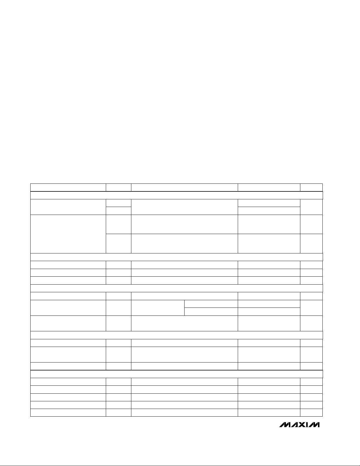
Typical Operating Characteristics
(V
STBY
= +5V, VDD= +12V, C1 = C2 = 0.1µF, TA = +25°C, unless otherwise noted.)
0
15
10
5
20
25
30
0 20001000 3000 4000 5000
SUPPLY CURRENT
vs. LOAD CAPACITANCE
MAX3209E-02
LOAD CAPACITANCE (pF)
SUPPLY CURRENT (mA)
120kbps
240kbps
460kbps
2 TRANSMITTERS AT DATA RATE
4 TRANSMITTERS AT 1/16 DATA RATE
3kΩ + C
L
5
15
10
25
20
30
35
10.8 12.011.4 12.6 13.2
SUPPLY CURRENT vs. SUPPLY VOLTAGE
MAX3209E-01
SUPPLY VOLTAGE (V)
SUPPLY CURRENT (mA)
460kbps
240kbps
120kbps
C1 = C2 = 0.1µF
2 TRANSMITTERS AT DATA RATE
4 TRANSMITTERS AT 1/16 DATA RATE
ALL TRANSMITTERS AT 3kΩ + 1000pF
Page 4

MAX3209E
±15kV ESD-Protected, 12V, Dual RS-232 Serial Port
with Low-Power Standby for Motherboards/Desktops
4 _______________________________________________________________________________________
Pin Description
PIN NAME FUNCTION
6, 7, 8, 12,
13, 14
T_IN TTL/CMOS Transmitter Inputs
9 V
STBY
Standby Power Supply for R5 and R10
11 C1+
Positive Terminal of the Inverting
Charge-Pump Capacitor
1–5, 15–19 R_OUT TTL/CMOS Receiver Outputs
10 V
DD
+12V Single-Supply Voltage
20–24,
34–38
R_IN RS-232 Receiver Inputs
25, 26, 27,
31, 32, 33
T_OUT RS-232 Transmitter Outputs
28 GND Ground
Figure 1. Slew-Rate Test Circuit and Timing Diagram
29 C1-
Negative Terminal of the Inverting
Charge-Pump Capacitor
30 V-
-12V generated by the inverting
charge pump
Typical Operating Characteristics (continued)
(V
STBY
= +5V, VDD= +12V, C1 = C2 = 0.1µF, TA = +25°C, unless otherwise noted.)
0
0.1
0.2
0.3
0.4
0.5
0.6
021 3456789
RECEIVER OUTPUT LOW VOLTAGE
vs. SINK CURRENT
MAX3209E-03
I
SINK
(mA)
RECEIVER OUTPUT LOW VOLTAGE (V)
0
1.5
1.0
0.5
2.0
2.5
3.0
3.5
4.0
4.5
5.0
0105 15202530
RECEIVER OUTPUT HIGH VOLTAGE
vs. SOURCE CURRENT
MAX3209E-04
I
SOURCE
(mA)
RECEIVER OUTPUT HIGH VOLTAGE (V)
DRIVER
INPUT
3.0V
1.5V
0
t
PHL
3.3V
V
OUT
SIGNAL
GENERATOR
t
F2
t
F1
3.0V
-3.0V
-3.3V
t
PLH
V
OH
0V
t
R2
t
R1
R
L
V
OL
C
L
Page 5

Detailed Description
±15kV ESD Protection
As with all Maxim devices, ESD-protection structures
are incorporated on all pins to protect against electrostatic discharges (ESD) encountered during handling
and assembly. The MAX3209E driver outputs and
receiver inputs have extra protection against static
electricity found in normal operation. Maxim’s engineers
developed state-of-the-art structures to protect these
pins against ±15kV ESD, without damage. After an ESD
event, the MAX3209E continues working without latchup.
ESD protection can be tested in several ways. The
transmitter outputs and receiver inputs are characterized for protection to the following:
1) ±15kV using the Human Body Model
2) ±8kV using the Contact-Discharge Method specified
in IEC 1000-4-2 (formerly IEC 801-2)
3) ±15kV using the Air-Gap Method specified in
IEC 1000-4-2 (formerly IEC 801-2)
ESD Test Conditions
ESD performance depends on a number of conditions.
Contact Maxim for a reliability report that documents
test setup, methodology, and results.
Human Body Model
Figure 2a shows the Human Body Model, and Figure
2b shows the current waveform it generates when discharged into a low impedance. This model consists of a
100pF capacitor charged to the ESD voltage of interest,
which is then discharged into the device through a
1.5kΩ resistor.
IEC 1000-4-2
Since January 1996, all equipment manufactured
and/or sold in the European community has been
required to meet the stringent IEC 1000-4-2 specification. The IEC 1000-4-2 standard covers ESD testing
and performance of finished equipment; it does not
specifically refer to integrated circuits. The MAX3209E
helps you design equipment that meets Level 4 (the
highest level) of IEC 1000-4-2, without additional ESDprotection components.
The main difference between tests done using the
Human Body Model and IEC 1000-4-2 is higher peak
current in IEC 1000-4-2. Because series resistance is
lower in the IEC 1000-4-2 ESD test model (Figure 3a), the
ESD withstand voltage measured to this standard is generally lower than that measured using the Human Body
Model. Figure 3b shows the current waveform for the
±8kV IEC 1000-4-2 Level 4 ESD Contact-Discharge test.
The Air-Gap test involves approaching the device with a
charge probe. The Contact-Discharge method connects
the probe to the device before the probe is energized.
MAX3209E
±15kV ESD-Protected, 12V, Dual RS-232 Serial Port
with Low-Power Standby for Motherboards/Desktops
_______________________________________________________________________________________ 5
Figure 3a. IEC 1000-4-2 ESD Test Model
Figure 2b. Human Body Model Current Waveform
Figure 2a. Human Body ESD Test Model
R
R
C
1M
CHARGE-CURRENT
LIMIT RESISTOR
HIGH-
VOLTAGE
DC
SOURCE
100pF
C
s
IP 100%
90%
AMPERES
36.8%
10%
0
0
t
RL
D
1500Ω
DISCHARGE
RESISTANCE
STORAGE
CAPACITOR
I
r
TIME
t
DL
CURRENT WAVEFORM
DEVICE
UNDER
TEST
PEAK-TO-PEAK RINGING
(NOT DRAWN TO SCALE)
HIGH-
VOLTAGE
DC
SOURCE
R
C
50M to 100M
CHARGE-CURRENT
LIMIT RESISTOR
C
150pF
s
R
D
330Ω
DISCHARGE
RESISTANCE
STORAGE
CAPACITOR
DEVICE
UNDER
TEST
Page 6

MAX3209E
±15kV ESD-Protected, 12V, Dual RS-232 Serial Port
with Low-Power Standby for Motherboards/Desktops
6 _______________________________________________________________________________________
Machine Model
The Machine Model for ESD testing uses a 200pF storage capacitor and zero-discharge resistance. It mimics
the stress caused by handling during manufacturing
and assembly. Of course, all pins (not just RS-232
inputs and outputs) require this protection during manufacturing. Therefore, the Machine Model is less relevant to the I/O ports than are the Human Body Model
and IEC 1000-4-2.
Applications Information
R5 and R10 Active in Standby Mode
The MAX3209E is placed in standby mode when VDDis
not present, provided that V
STBY
remains at +3V to
+5.5V. In standby mode, receivers R5 and R10 remain
active, consuming 100µA max while unloaded. Standby
mode allows activity to be sensed on the serial ports so
that main power can be restored by the power-management unit, as shown in Figure 4.
Layout Considerations
Use proper layout to ensure other devices on your
board are not damaged in an ESD strike. Currents as
high as 60A can instantaneously pass into ground, so
be sure to minimize the ground-lead return path to the
power supply. A separate return path to the power supply is recommend. Trace widths should be greater than
40 mils. Bypass VDDand V
STBY
with 0.1µF capacitors
as close to the part as possible to ensure maximum
ESD protection.
The MAX3209E is not sensitive to power-supply
sequencing, and therefore requires no external protection diodes.
Interconnection with 3V and 5V Logic
The MAX3209E can directly interface with various 3V
and 5V logic families, including ACT and HCT CMOS.
See Table 1 for more information on possible combinations of interconnections.
Mouse Driveability
The MAX3209E has been specifically designed to
power serial mice while operating from low-voltage
power supplies. It has been tested with leading mouse
brands from manufacturers such as Microsoft and
Logitech. The MAX3209E successfully drove all serial
mice tested and met their respective current and voltage requirements.
Figure 4. MAX3209E in Standby Mode
Figure 3b. IEC 1000-4-2 ESD-Generator Current Waveform
SYSTEM POWER-
SUPPLY VOLTAGE
(V)
V
STBY
SUPPLY
VOLTAGE
(V)
3.33.3
COMPATIBILITY
Compatible with all
CMOS families.
55
Compatible with all
TTL and CMOS families.
3.35
Compatible with ACT
and HCT CMOS, and
with AC, HC, or
CD4000 CMOS.
Table 1. Logic Family Compatibility with
Various Supply Voltages
I
100%
90%
PEAK
I
10%
tR = 0.7ns to 1ns
30ns
60ns
+12V
SUPER
I/O
t
POWER-MANAGEMENT UNIT
V
STBY
R5
R10
R_
T_
V
DD
MAX3209E
ALL OTHER
RECEIVERS
INACTIVE
ALL TRANSMITTERS
INACTIVE
GND
Page 7

MAX3209E
±15kV ESD-Protected, 12V, Dual RS-232 Serial Port
with Low-Power Standby for Motherboards/Desktops
_______________________________________________________________________________________ 7
TRANSISTOR COUNT: 774
___________________Chip Information
__________Typical Operating Circuit
+5V
+12V +5V +12V
0.1µF
V
STBYVDD
T1
0.1µF0.1µF
V
V
CC
MAX3186MAX3209E
R1
0.1µF
DD
TTL/CMOS
C1
0.1µF
LOGIC
T2
INTERCONNECTING
0.1µF
C2
RS-232
CABLE
V+
V+
V-
TX
T3
I/O
C1+
C1-
GND
R1
R2
R3
R4
R5
T4
T5
T6
R6
R7
R8
R9
R10
V-
R2
R3
T1
T2
T3
T4
T5
GND V
MOUSE
-12V
TTL/CMOS
LOGIC
I/O
SS
0.1µF
Page 8

MAX3209E
±15kV ESD-Protected, 12V, Dual RS-232 Serial Port
with Low-Power Standby for Motherboards/Desktops
Maxim cannot assume responsibility for use of any circuitry other than circuitry entirely embodied in a Maxim product. No circuit patent licenses are
implied. Maxim reserves the right to change the circuitry and specifications without notice at any time.
8
_____________________Maxim Integrated Products, 120 San Gabriel Drive, Sunnyvale, CA 94086 408-737-7600
© 1999 Maxim Integrated Products Printed USA is a registered trademark of Maxim Integrated Products.
________________________________________________________Package Information
TSSOP, 4.40mm.EPS
 Loading...