

Page 1
0.560-INCH
SEVEN SEGMENT DISPLAYS
HIGH EFFICIENCY GREEN MAN6400 SERIES
.750"
(19.05 mm)
+.010"
DIGIT = 1
PAR T
IDENTIFICATION
PIN #1
(NOTE SQUARE
BASE ON
LEAD)
.750"
(19.05 mm)
+.010"
(8.13 mm)
PAR T
IDENTIFICATION
PIN #1
.100" TYP
(2.54 mm)
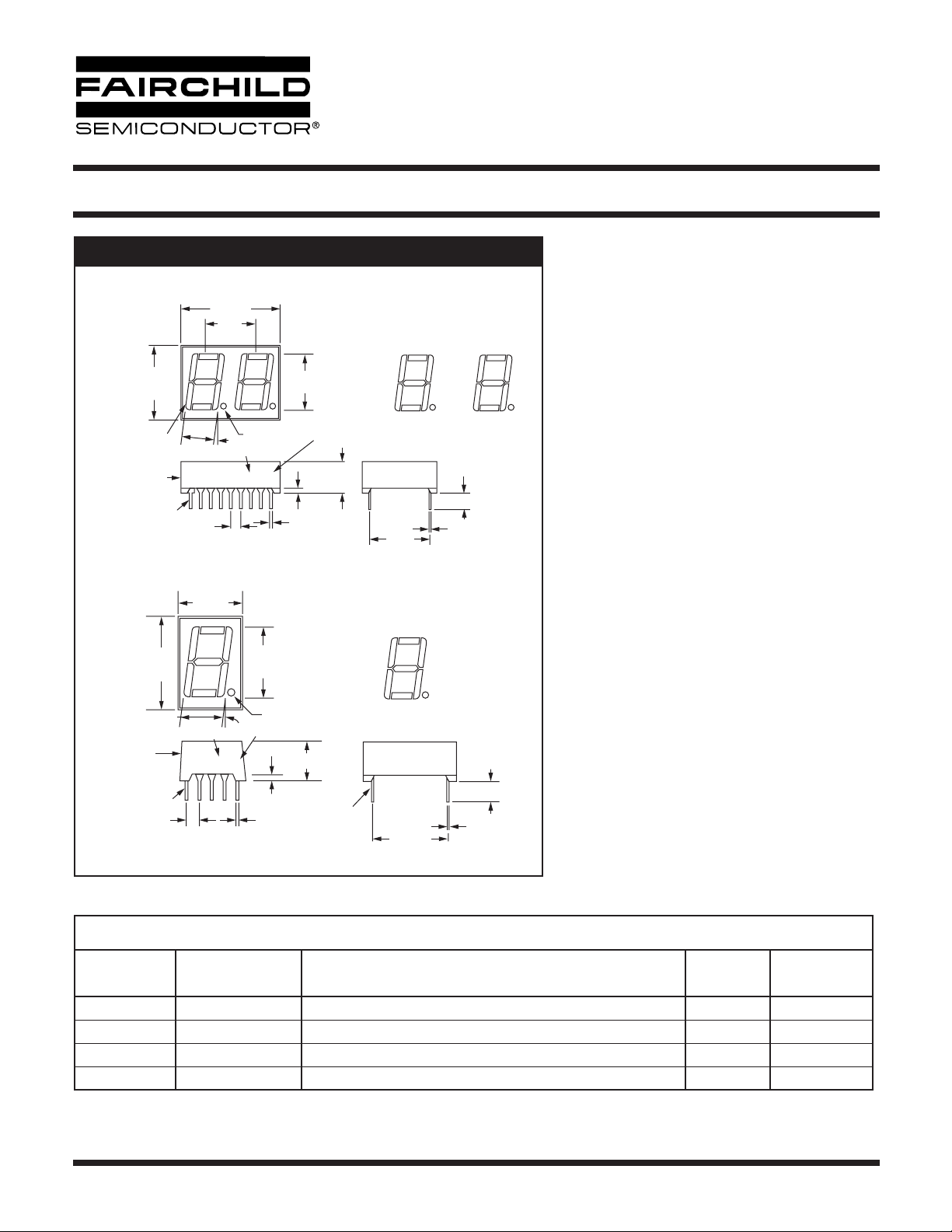
PACKAGE DIMENSIONS
.985"
(25.02 mm)
±.010"
.500"
(12.70 mm)
.560"
(14.22 mm)
.320"
.320"
(8.13 mm)
PART NO.
.100"
(2.54 mm)
.480"
(12.20 mm)
±.010"
DATE CODE
PAR T
NO.
8°
DATE CODE
XYYZZ
.066" DIA
(1.68 mm)
XYY
.020"
(0.51 mm)
+.004"
-.000"
.560"
+0.010"
(14.22 mm)
8°
LIGHT INTENSITY CAT.
.020"
(0.51 mm)
+.004"
-.000"
.066" DIA
.050"
(1.27 mm)
LIGHT
INTENSITY CAT.
.050"
+.004"
-.000"
(1.27 mm)
(8.00 mm)
.315"
(8.00 mm)
±.010"
.315"
±.010"
PIN #5
F
G
E
D
.600"
(15.24 mm)
+.015"
A
F
G
E
D
.600"
(15.24 mm)
+.015"
A
B
C
DP
(0.25 mm)
B
C
DP
F
E
.160"
(4.06 mm)
+.015"
.010"
+.007"
-.000"
(4.06 mm)
.010"
(0.25 mm)
+.007"
-.000"
G
D
.160"
+.015"
Description
The MAN6400 Series is a family of large digits
which includes double and single digits. The series
features the sculptured font which minimizes “gappiness” at the segment intersections. All models have
A
C
right hand decimal points and are available in common anode or common cathode configuration. This
B
device has a Grey face and clear segments to
enhance ON and OFF contrast.
DP
Features
• High Efficiency Green nitrogen-doped GaAsP on
GaP
• Large, easy to read, digits
• Common anode or common cathode models
•Fast switching — excellent for multiplexing
•Low power consumption
• Bold solid segments that are highly legible
• Solid state reliability — long operation life
• Rugged plastic construction
• Directly compatible with integrated circuits
• High brightness with high contrast
• Categorized for Luminous Intensity (See Note 5)
• Wide angle viewing...150°
•Low forward voltage
•Two-digit package simplifies alignment and
assembly
Applications
For industrial and consumer applications such as:
• Digital readout displays
• Instrument panels
•Point of sale equipment
• Digital clocks
• TV and radios
MODEL NUMBERS
Part Number Color Description
Package
Drawing
MAN6410 High Eff. Green 2 Digit; Common Anode; Rt. Hand Decimal A A
MAN6440 High Eff. Green 2 Digit; Common Cathode; Rt. Hand Decimal A B
MAN6460 High Eff. Green Single Digit; Common Anode; Rt. Hand Decimal B C
MAN6980 High Eff. Green Single Digit; Common Cathode; Rt. Hand Decimal B D
© 2003 Fairchild Semiconductor Corporation
Page 1 of 6
Pin Out
Specification
7/16/03
Page 2
Ω Ω
0.560-INCH
SEVEN SEGMENT DISPLAYS
HIGH EFFICIENCY GREEN MAN6400 SERIES
RECOMMENDED OPTICAL FILTERS
For optimum ON and OFF contrast, one of the following filters or equivalents should be used over the display:
Device Type Filter
Panelgraphic Green 48
MAN6400 Series
ELECTRO-OPTICAL CHARACTERISTICS
(Per Diode 25°C Free Air Temperature Unless Otherwise Specified)
Homalite 100-1440 Green
Panelgraphic Grey 10
Homalite 100-1266 Grey
Min. Typ. Max. Units Test Conditions
Luminous Intensity, digit average (See Note 1) 510 2200 µcd I
Peak emission wavelength 565 nm
Spectral line half width 30 nm
Forward voltage
Segment
Decimal point
Dynamic resistance
Segment
Decimal point
Capacitance
Segment
Decimal point
Reverse current
Segment
Decimal point
Ratio I
L
2.1
2.1
26
26
35
35
2.8
2.8
100
100
2:1 — I
V
V
pF
pF
µA
µA
= 10 mA
F
I
= 20 mA
F
I
= 20 mA
F
I
= 20 mA
F
I
= 20 mA
F
V = 0
V = 0
V
R
V
R
= 10 mA
F
ABSOLUTE MAXIMUM RATINGS
MAN64X0
Power dissipation at 25°C ambient 600mW
Derate linearly from 50°C
Storage and operating temperature -40°C to +85°C
Continuous forward current
Total
Per segment
Decimal point
Reverse voltage
Per segment
Decimal point
Soldering time at 260°C (See Notes 3 and 4) 5 sec.
30 mA
30 mA
6.0 V
6.0 V
= 3.0V
= 3.0V
© 2003 Fairchild Semiconductor Corporation
Page 2 of 6
7/16/03
Page 3

HIGH EFFICIENCY GREEN MAN6400 SERIES
TYPICAL THERMAL CHARACTERISTICS
0.560-INCH
SEVEN SEGMENT DISPLAYS
Thermal resistance junction to free air φ
Wavelength temperature coefficient (case temperature) 1.0Å/°C
Forward voltage temperature coefficient -2.0 mV/°C
Notes:
1. The digit average Luminous Intensity is obtained by summing the Luminous Intensity of each segment and dividing by the total
number of segments. Intensity will not vary more than ±33.3% between all segments within a digit.
2. The curve in Figure 3 is normalized to the brightness at 25°C to indicate the relative efficiency over the operating temperature
range.
3. Leads of the device immersed to 1/16 inch from the body. Maximum device surface temperature is 140°C.
4. For flux removal, Freon TF, Freon TE, Isoproponal or water may be used up to their boiling points.
5. All displays are categorized for Luminous Intensity. The Intensity category is marked on each part as a suffix letter to the part
number.
JA
160°C/W
ELECTRICAL CONNECTIONS
Pin
No.
1 Cathode E 1 Anode E 1 Cathode E Anode E
2 Cathode D 1 Anode D 1 Cathode D Anode D
3 Cathode C 1 Anode C 1 Common Anode Common Cathode
4 Cathode D.P. 1 Anode D.P. 1 Cathode C Anode C
5 Cathode E 2 Anode E 2 Cathode D.P. Anode D.P.
6 Cathode D 2 Anode D 2 Cathode B Anode B
7 Cathode G 2 Anode G 2 Cathode A Anode A
8 Cathode C 2 Anode C 2 Common Anode Common Cathode
9 Cathode D.P. 2 Anode D.P. 2 Cathode F Anode F
10 Cathode B 2 Anode B 2 Cathode G Anode G
11 Cathode A 2 Anode A 2
12 Cathode F 2 Anode F 2
13 Anode Digit 2 Cathode Digit 2
14 Anode Digit 1 Cathode Digit 1
15 Cathode B 1 Anode B 1
16 Cathode A 1 Anode A 1
17 Cathode G 1 Anode G 1
18 Cathode F 1 Anode F 1
A
MAN6410
ELECTRICAL CONNECTIONS
B
MAN6440
C
MAN6460
D
MAN6480
© 2003 Fairchild Semiconductor Corporation
Page 3 of 6
7/16/03
Page 4

HIGH EFFICIENCY GREEN MAN6400 SERIES
TYPICAL CHARACTERISTIC CURVES
0.560-INCH
SEVEN SEGMENT DISPLAYS
100
90
80
= mA
F
70
60
50
40
30
20
Forward Current I
10
0
1.0 2.0
Forward Voltage (V
Fig. 1 Forward Current vs. Forward Voltage
1000
800
600
400
200
100
80
60
40
20
Maximum Peak Current mA
0
10 100 1000
10 KHz
3.0 KHz
Pulse Duration µs
1.0 KHz
(Dotted Line
Indicates
Pulsed Operation
See Figs. 3, 5)
3.0 4.0
) – Volts
F
300Hz
100Hz
10000
4.0
Normalized at IF = 10 mA
3.0
2.0
1.0
Relative Luminous Intensity
0
051015 20 25 30
DC Forward Current – IF mA
Fig. 2. Relative Luminous Intensity vs. DC Forward Current
130
120
110
100
90
Relative Intensity %
80
70
-55 -25 0 25 50 75 100
Temperature – T
Normalized
at 25°C
°C
A
Fig. 3 Maximum Peak Current vs. Pulse Duration
© 2003 Fairchild Semiconductor Corporation
4.0
3.0
at 10mA DC)
2.0
L
1.0
Relative Efficiency
at drive/I
L
(I
I
= 20 mA
F (AVG)
10 mA
5 mA
2.5 mA
0
2.0
Fig. 5 Relative Efficiency vs. Duty Cycle
5.0 19 20 50 DC
% Duty Cycle
Page 4 of 6
Fig. 4 Relative Luminous Intensity vs. Temperature
7/16/03
Page 5

HIGH EFFICIENCY GREEN MAN6400 SERIES
INTERNAL CONNECTIONS
0.560-INCH
SEVEN SEGMENT DISPLAYS
14
FIRST DIGIT SECOND
E1D2C3B15A16G17F18DP
E1D2C4B6A7G10F
4
MAN6410 MAN6640
38
MAN6460 MAN6480
13
DIGIT
E5D6G7C8B10A11F12DP
DP
9
5
9
14
FIRST DIGIT SECOND DIGIT
E1D2C3B15A16G17F18DP4E5D6G7C8B10A11F12DP
38
E1D2C4B6A
7
13
9
G10F
DP
9
5
© 2003 Fairchild Semiconductor Corporation
Page 5 of 6
7/16/03
Page 6

0.560-INCH
SEVEN SEGMENT DISPLAYS
HIGH EFFICIENCY GREEN MAN6400 SERIES
DISCLAIMER
FAIRCHILD SEMICONDUCTOR RESERVES THE RIGHT TO MAKE CHANGES WITHOUT FURTHER NOTICE TO
ANY PRODUCTS HEREIN TO IMPROVE RELIABILITY, FUNCTION OR DESIGN. FAIRCHILD DOES NOT ASSUME
ANY LIABILITY ARISING OUT OF THE APPLICATION OR USE OF ANY PRODUCT OR CIRCUIT DESCRIBED HEREIN;
NEITHER DOES IT CONVEY ANY LICENSE UNDER ITS PATENT RIGHTS, NOR THE RIGHTS OF OTHERS.
LIFE SUPPORT POLICY
FAIRCHILD’S PRODUCTS ARE NOT AUTHORIZED FOR USE AS CRITICAL COMPONENTS IN LIFE SUPPORT DEVICES
OR SYSTEMS WITHOUT THE EXPRESS WRITTEN APPROVAL OF THE PRESIDENT OF FAIRCHILD SEMICONDUCTOR
CORPORATION. As used herein:
1. Life support devices or systems are devices or systems
which, (a) are intended for surgical implant into the body, or
(b) support or sustain life, and (c) whose failure to perform
when properly used in accordance with instructions for use
provided in the labeling, can be reasonably expected to
result in a significant injury of the user.
2. A critical component in any component of a life support
device or system whose failure to perform can be
reasonably expected to cause the failure of the life support
device or system, or to affect its safety or effectiveness.
© 2003 Fairchild Semiconductor Corporation
Page 6 of 6
7/16/03
 Loading...