

Page 1
MAAMSS0017
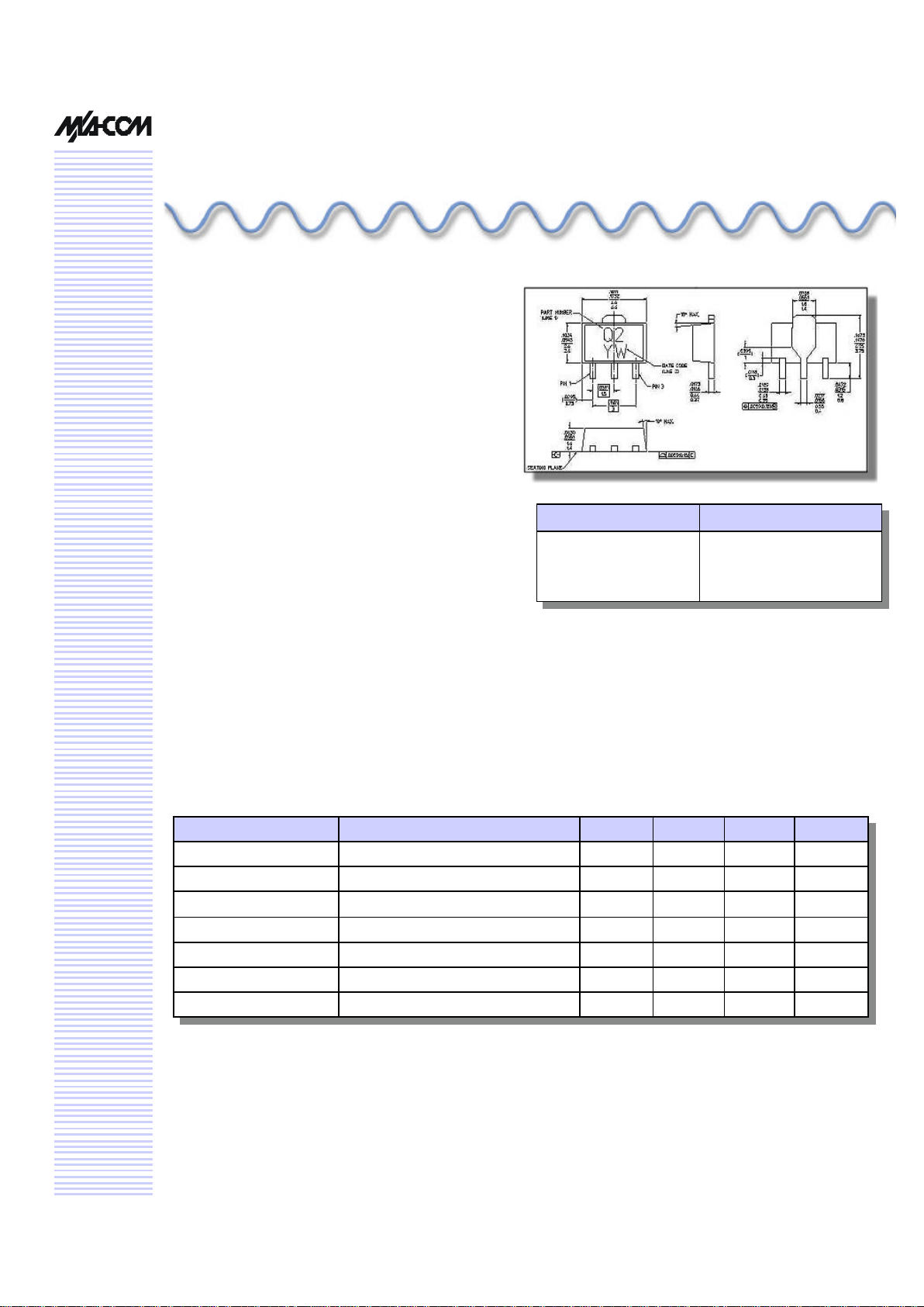
SOT-89 Plastic Package
V 1.00
Features
• Low Cost Plastic SOT-89 Package
• Broadband Operation
• Output Intercept Point of +40 dBm
• Output P1dB of +22 dBm
• High Efficiency
• 50 ohm Input /Output match
• Typical Gain of 18 dB
Description
M/A-COM’s MAAMSS0017 IF driver amplifier is a
GaAs MMIC which exhibits high OIP3 as well as high
gain and low power consumption in a low-cost miniature SOT89 surface mount plastic package. The
MAAMSS0017 employs a monolithic single stage
design featuring a convenient 50 ohm input/output
impedance that minimizes the number of external
components required. The device runs off a single
+5 volt supply and draws 70 mA typically. The design provides excellent performance from 50 to 450
MHz.
The MAAMSS0017 is fabricated using M/A-COM’s
iHBT process to realize low current and high power
functionality. The process features full passivation
for increased performance and reliability.
Parameter Test Conditions Units Min Typ Max
Gain2 F = 50-450 MHz dB 18
Noise Figure3 F = 50-450 MHz dB 4.4
Input Return Loss F = 50-450 MHz dB 12
Output Return Loss F = 50-450 MHz dB 15
1dB Compression F = 50-450 MHz dBm 22
Output IP3 4 F = 50-450 MHz dBm 40
Current Vs = 5 V mA 70
Electrical Specifications1: TA = +25° C, Vs = 5 V,Is = 70 mA
Broadband IF Driver Amplifier
50 - 450 MHz
Advanced
Part Number Package
MAAMMSS0017TR
MAAMSS0017TR3000
1000 Piece Tape and Reel
1
3000 Piece Tape and Reel
1
1. Reference Application Note M513 for reel size information.
1. All measurements taken in a 50 ohm system unless otherwise specified.
2. Gain varies at –0.008 dB/°C typical.
3. Noise figure varies at 0.007 dB/°C typical
4. OIP3 measured with Pout/Tone = +5 dBm, Tone spacing = 10 MHz
Page 2
Broadband IF Driver Amplifier 50-450 MHz
MAAMSS0017
Specifications subject to change without notice.
n North America: Tel. (800) 366-2266
n Asia/Pacific: Tel.+81-44-844 -8296, Fax +81-44-844-8298
n Europe: Tel. +44 (1344) 869 595, Fax+44 (1344) 300 020
Visit www.macom.com for additional data sheets and product information.
V 1.00
2
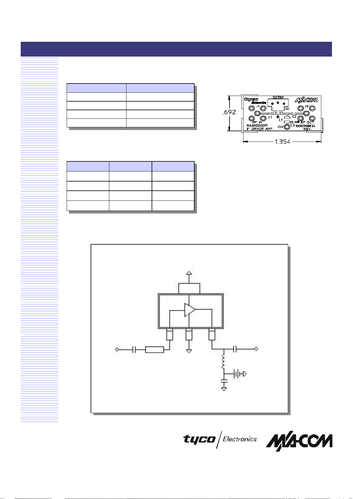
Schematic Including Off-Chip Components
Pin Configuration
Pin No. Function
1 RF In
2 GND
3 RF Out/Bias
4 GND
Off-Chip Component Values
Part Value Package
C1 100 pF 0603
C2 150 pF 0603
C3 10000 pF 0603
L1 180 nH 1008
Board Lay-out
RF In
Pin 1
100 mil
Z = 50 ohms
RF Out
C2
L1
C3
+ 5V
C1
Page 3

Broadband IF Driver Amplifier 50-450 MHz
MAAMSS0017
Specifications subject to change without notice.
n North America: Tel. (800) 366-2266
n Asia/Pacific: Tel.+81-44-844 -8296, Fax +81-44-844-8298
n Europe: Tel. +44 (1344) 869 595, Fax+44 (1344) 300 020
Visit www.macom.com for additional data sheets and product information.
V 1.00
Typical Performance Curves
OIP3 vs. Frequency
OPI3 vs. Frequency
20
25
30
35
40
45
50
50 100 150 200 250 300 350 400 450
Frequency (MHz)
OIP3 (dBm)
Noise Figure vs. Frequency Vs = 5V, Is = 70 mA
Noise Figure vs. Frequency
0
1
2
3
4
5
6
50 100 150 200 250 300 350 400 450
Frequency (MHz)
Noise Figure (dB)
S-Parameters vs. Frequency
-30.0
-20.0
-10.0
0.0
10.0
20.0
0 50 100 150 200 250 300 350 400 450 500
Frequency (MHz)
Magnitude (dB)
S21
S11
S22
S Parameters, Vs = 5V, Is = 70 mA
 Loading...